Limited Wa anty
T oubleshooting
All products m nuf ctured by Cooper Controls nd identified with the Greeng te br nd re w rr nted to be free from defects in
m teri l nd workm nship nd sh ll conform to nd perform in ccord nce with Seller’s written specific tions for period of: Five
(5) ye rs from d te of shipment for ll occup ncy sensors nd Three (3) ye rs from d te of f ctory invoice for our h rdw re nd
softw re on Lighting Control P nels. We w rr nty ll our st nd rd rel ys for period of 10 ye rs from d te of f ctory invoice. We
gu r ntee the perform nce of our system to specific tions or your money b ck. This w rr nty will be limited to the rep ir or
repl cement, t Seller’s discretion, of ny such goods found to be defective, upon their uthorized return to Seller. This limited
w rr nty does not pply if the goods h ve been d m ged by ccident, buse, misuse, modific tion or mis pplic tion, by d m ge
during shipment or by improper service. There re no w rr nties, which extend beyond the herein bove-limited w rr nty, INCLUD-
ING, BUT NOT LIMITED TO, THE IMPLIED WARRANTY OF MERCHANTABILITY AND THE IMPLIED WARRANTY OF FITNESS. No
employee, gent, de ler, or other person is uthorized to give ny w rr nties on beh lf of the Seller or to ssume for the Seller ny
other li bility in connection with ny of its goods except in writing nd signed by the Seller. The Seller m kes no represent tion
th t the goods comply with ny present or future feder l, st te or loc l regul tion or ordin nce. Compli nce is the Buyer’s respon-
sibility. The use of the Seller’s goods should be in ccord nce with the provision of the N tion l Electric l Code, UL nd/or other
industry or milit ry st nd rds th t re pertinent to the p rticul r end use. Inst ll tion or use not in ccord nce with these codes
nd st nd rds could be h z rdous.
Cooper Controls
203 Cooper Circle, Peachtree City, GA 30269
800-553-3879
www.coopercontrol.com
P/N SWA-PTA Rev A
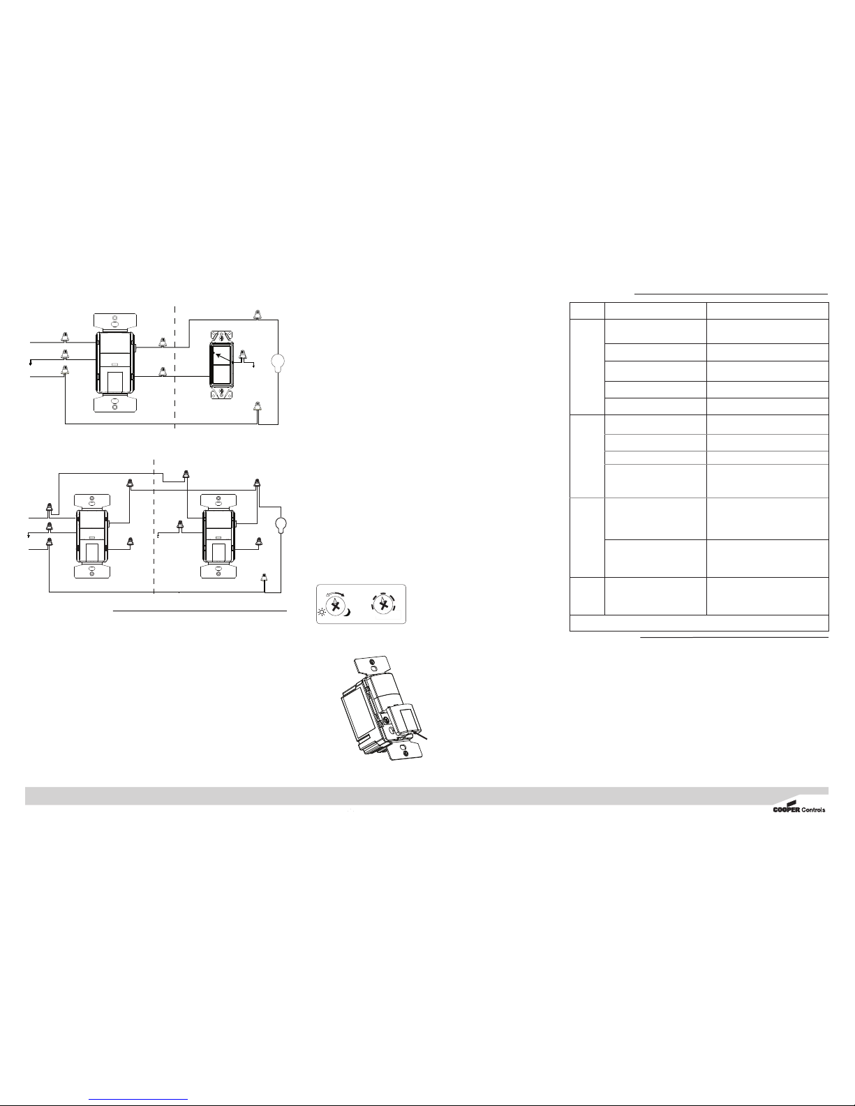
Issue Poss ble Causes Suggest ons
Lights
Will Not
Turn ON
automatically
(For OSW-P-
1001-120
Only)
Circuit breaker is turned FF, or fuse is
blown Turn circuit breaker N, or replace fuse
Bulb is defective Replace light bulb
Poor connection Verify all wiring connections
Control may be wired incorrectly Check wiring
Daylight sensing prevents lights N Re-adjust daylight sensing level
L ght does
not automat-
cally turn
OFF.
Motion is still present Make sure there is no motion during the Time
Delay period
Time Delay has not expired No action needed or shorten TIME DELAY
Control may be wired incorrectly Check wiring
Switch is being triggered by air vent or
other heat source
Move switch to the other switch location (if a 3-
way), or determine the source triggering the
switch, and alter the air flow.
Lights
Will Not
Stay ON
Motion is not detected Create movement in front of the sensor for
5 seconds
TIME control is set for too short a delay Set switch TIME control to longer time period
Remote
switch does
not work
Control may be wired incorrectly Check wiring
If l ghts w ll not operate properly, call Techn cal Serv ces at 1-800-553-3879
2. Remove the existing switch in the other 3-way location where the second sensor will be
installed.
a. The sensor black wire will connect to the black wire coming from the first Wall Box.
b. The sensor red wire will connect to the red wire coming from the first Wall Box and
to the black wire going to the light fixture.
c. The sensor blue wire is not used and should be capped FF with a wire nut.
d. The sensor green wire will connect to the ground wire in the Wall Box.
e. Install the sensor loosely using the mounting screws provided.
3. Apply power and wait one minute. Verify that the sensors work by pressing the N/ FF
buttons on each sensor. If the light does not turn N and FF from either or both sensors,
you must swap the red and black sensor wire N that sensor.
4. Re-install the sensor loosely, apply power again, and verify the sensor works by pushing
the N/ FF button to verify the lights turn N and FF. You must wait 2 seconds between
button presses.
5. Turn power FF and go to C MPLETING THE INSTALLATI N.
Printed in China
Installe Adjustments
First Location Second Location
2 traveler wires are required
DIAGRAM 3: SENSORS IN BOTH LOCATIONS
OSW-P-0801-120 or VSW-P-0801-120 Sensor
OSW-P-0801-120 or VSW-P-0801-120 Sensor
Light Fixture
Red Traveler
Black Traveler
White
Neutral
White
Neutral
White
Neutral
Ground
Bare
Ground
Bare GreenGreen
3-Way
Blue
3-Way
Blue
Output
Red
Hot
Black
Black
Hot
Black
Hot
Black Output
Red
Hot
Output
Red
Blue
3-Way Red Traveler
Black Traveler
Light Fixture
White
Black
Hot
Neutral
Ground
BlackBlack
Bare Green
White
First Location Second Location
White Neutral
2 traveler wires are required
DIAGRAM 2B: SENSOR IN LOCATION WITH HOT WIRE
3-Way
Switch
OSW-P-0801-120 or
VSW-P-0801-120 sensor
Ground
Bare
LIGHT LEVEL
TURN TO SET
FIGURE 5:
5
1
0
2
0
3
0
T
E
S
T
TIME DELAY
C MPLETING THE INSTALLATI N:
1. Secure sensor into the Wall Box using two mounting screws provided. Turn the circuit
breaker N.
2. Allow the sensor to stabilize for one minute. The sensor is now ready to detect motion.
3. Verify that Power is N by pushing the N/ FF button. Lights should turn N.
4. N TE - The sensor Time Delay is factory preset ( SW-P-0801-120 = 5 minutes; VSW-P-
0801-120 = 30 minutes).
5. If you want to change the Time Delay proceed as follows:
a. Remove the button from the sensor by pressing in the hooks on the button, and then lift
up on the button as shown in Fig. 4.
b. Set the Time Delay using the dial on the right side by using a small Phillips screwdriver.
Align the arrow on the dial to desired Time Delay.
c. To allow the installer to quickly confirm that the sensor is functioning properly the Time
Delay can be set to TEST. This will set a Time Delay of 5 seconds, which allows quick
feedback that the sensor is working properly.
6. Replace Pushbutton by sliding it upward into the slots in the front housing and push down
until the button hook snaps into place.
7. Push the N/ FF button to verify that the lights turn N/ FF, and that the button
operates freely.
8. Install the Wallplate.
Daylight Sensing Adjustment ( SW-P-0801-120 only):
The Daylight sensing feature prevents lights from turning N when the room is adequately
illuminated by natural light.
N TE - The factory setting for this adjustment is fully counter-clockwise, which permits motion
detection to turn the lights N regardless of the ambient light level in the room.
This adjustment requires a small Phillips screwdriver and must be made when the light level in the
room is at the desired level for the lights to turn N.
1. Remove the N/ FF Pushbutton to access the light level adjustment (See Figure 4)
2. Turn the LIGHT LEVEL dial to the full clockwise position.
3. Turn the TIME DELAY dial to the TEST position and hold the screwdriver on the dial. Do not
move for 5 seconds until the light turns FF. Immediately turn the dial back to the full counter
clockwise position. The light should stay FF.
4. Stand to the side of the sensor to allow the device to sense the normal light level in the room.
5. Move your hand continually back and forth about 2 feet in front of the sensor while slowly
turning the LIGHT LEVEL dial counter-clockwise until the light turns N.
6. Adjust the Time Delay to the desired setting.
7. The Light Level adjustment is now complete. Replace the N/ FF Pushbutton.
WIRING DIAGRAM 2B: SENSOR IN ONE LOCATION WITH HOT WIRE
WIRING DIAGRAM 3: SENSORS IN BOTH LOCATIONS
FIGURE 5
FIGURE 4
2. LIFT UP
BUTTON
1. PRESS TO
RELEASE HOOK


