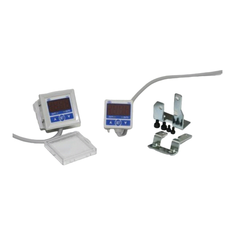
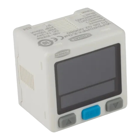
Schmalz VS-P-W-D K 3C-D User manual

DE Kurz-Bedienungsanleitung Vakuum-/Druckschalter VS-V/P-W-D K 3C-D.................................................... 2
EN Short Instruction Manual Vacuum/pressure switch VS-V/P-W-D K 3C-D...................................................... 9
FR Manuel d'utilisation simplifié Vacuostat/pressostat VS-V/P-W-D K 3C-D..................................................... 16
IT Manuale d’uso in breve Vacuostato/pressostato VS-V/P-W-D K 3C-D........................................................... 24
ES Manual de instrucciones abreviado Interruptor de vacío/presión VS-V/P-W-D K 3C-D......................... 32
WWW.SCHMALZ.COM 30.30.01.02016 · 01 · 11/19

DEUTSCH
Hinweis: Die Kurz-Bedienungsanleitung wurde in deutscher Sprache erstellt. Sie beschreibt die grund-
legenden Funktionen und dient erfahrenen Anwendern als Schnelleinstieg. Die vollständige
Beschreibung ist der ausführlichen Betriebsanleitung zu entnehmen unter www.schmalz.com oder
auf Anfrage. Diese Kurz-Bedienungsanleitung erhebt keinen Anspruch auf Vollständigkeit. Für
künftige Verwendung aufbewahren. Technische Änderungen, Druckfehler und Irrtümer vorbehalten.
J. Schmalz GmbH · Johannes-Schmalz-Str. 1 · D-72293 Glatten · T: +49 7443 2403-0
schmalz@schmalz.de
1 Die Technische Dokumentation ist Teil des Produkts
1. Für einen störungsfreien und sicheren Betrieb befolgen Sie die Hinweise in den Dokumenten.
2. Bewahren Sie die Technische Dokumentation in der Nähe des Produkts auf. Sie muss für das Per-
sonal jederzeit zugänglich sein.
3. Geben Sie die Technische Dokumentation an nachfolgende Nutzer weiter.
ðBei Missachtung der Hinweise in dieser Kurz-Betriebsanleitung kann es zu lebensgefährlichen
Verletzungen kommen!
ðFür Schäden und Betriebsstörungen, die aus der Nichtbeachtung der Hinweise resultieren, über-
nimmt Schmalz keine Haftung.
Wenn Sie nach dem Lesen der Technischen Dokumentation noch Fragen haben, wenden Sie sich an
den Schmalz-Service unter:
www.schmalz.com/services
2 Bestimmungsgemäße Verwendung
Der Vakuum-/Druckschalter dient zum Messen und Anzeigen von Vakuum bzw. Druck und gibt dies
proportional als elektrische Spannung 1…5V an einem Analogausgang aus.
Dieses Gerät wurde ausschließlich für die industrielle und gewerbliche Nutzung entwickelt, konstruiert
und gebaut. Eine private Nutzung ist ausgeschlossen.
Der Vakuum-/Druckschalter ist nach dem Stand der Technik gebaut und wird betriebssicher ausge-
liefert, dennoch können bei der Verwendung Gefahren entstehen.
Die Beachtung der Technischen Daten und der Montage- und Betriebshinweise in dieser Anleitung
gehören zur bestimmungsgemäßen Verwendung.
2 / 40 DE · 30.30.01.02016 · 01 · 11/19

3 Aufbau vom Vakuum- /Druckschalter
1UP-TASTE
1
4
3
2
6
8
5
7
2 Display
3DOWN-TASTE
4SET-TASTE
5 Elektrischer Anschluss/
Anschlusskabel
6 Messmedium
7 O-Ring
8 Befestigungsgewinde
2xM5
4 Schalter pneumatisch anschließen
4Der pneumatische Anschluss erfolgt über
Gewinde G1 oder G2. Verbinden Sie geeignete
Rohrleitungen mit dem passenden Anschluss. Um
den Innensechskantstecker oder das Anschluss-
stück anzuschließen, halten Sie den Sechskantteil
des Pneumatikanschlusses fest und befestigen Sie
ihn. Ein Anzugsdrehmoment von 13 Nm oder
weniger anwenden.
DE · 30.30.01.02016 · 01 · 11/19 3 / 40

5 Elektrischer Anschluss
HINWEIS
Falsche Spannungsversorgung
Zerstörung der integrierten Elektronik
4Produkt über ein Netzgerät mit Schutzkleinspannung (PELV) betreiben.
4Für sichere elektrische Trennung der Versorgungsspannung gemäß EN60204
sorgen.
4Steckverbinder nicht unter Zug- und/oder elektrischer Spannung verbinden oder
trennen.
HINWEIS
Anschließen bei eingeschalteter Stromversorgung
Beschädigung der Elektronik und / oder Fehlfunktionen
4Die Stromversorgung abschalten, bevor Kabel angeschlossen werden!
Der Vakuumschalter wird inkl. 4-adrigem Anschlusskabel mit offenen Kabelenden geliefert.
Den Vakuum-/Druckschalter gemäß Elektroschaltplan in Ihre Anwendung integrieren.
4 / 40 DE · 30.30.01.02016 · 01 · 11/19

Elektroschaltpläne
VS-☐-W-D NPN K 3C-D (1 NPN+Analog Output
(1-5V))
OUT Analog
VS-☐-W-D PNP K 3C-D (1 PNP+Analog Output
(1-5V))
OUT Analog
VS-☐-W-D NPN K 3C-D (2 NPN Output) VS-☐-W-D PNP K 3C-D (2 PNP Output)
Zuordnung der Kabelfarben
Leitung Kabelfarbe
DC (+) braun
OUT1 schwarz
OUT2 / OUT Analog weiß
DC (-) blau
DE · 30.30.01.02016 · 01 · 11/19 5 / 40

6 Betrieb
6.1 Sicherheitshinweise
HINWEIS
Betriebsdruck über dem empfohlenen maximalen Druck
Beschädigung des Schalters
4Den Vakuum-/Druckschalter nur innerhalb des Nenndruckbereichs verwenden.
Den Vakuumschalter nicht fallen lassen oder Stößen aussetzen.
Auch wenn das Gehäuse unbeschädigt ist können interne Komponenten beschädigt sein und zu Fehl-
funktionen führen.
6.2 Einrichten der Grundfunktionen
Der Vakuum-/Druckschalter wird über drei Tasten bedient:
SET-TASTE
UP-TASTE
DOWN-TASTE
Einstellungen werden über Softwaremenüs vorgenommen.
Folgende Menüs stehen zur Verfügung:
• Grundmenü: Für Standardanwendungen
• Erweiterte Funktionen Menü: Für Anwendungen mit besonderen Anforderungen
6 / 40 DE · 30.30.01.02016 · 01 · 11/19

Grundmenü aktivieren und Parameter auswählen
üDer Vakuum-/Druckschalter befindet sich im Messmodus.
1. Die Taste mehr als 3 Sekunden drücken.
ðDer erste Parameter im Grundmenü ist ausgewählt. Dies wird in der unteren Anzeige durch
ot1 angezeigt.
2. Die Taste oder drücken um den gewünschten Funktionsmodus des Ausgangs OUT1
auszuwählen.
3. Durch drücken der Taste wird der nächste Parameter ausgewählt und der ausgewählte
oder eingestellte Parameterwert wird übernommen.
6.3 Funktionen im Grundmenü
Folgende Tabelle zeigt eine Übersicht der Anzeige-Codes und der Parameter im Grundmenü:
Parameter Anzeige-Code
der unteren
Anzeige
Anzeige-Code
der Hauptan-
zeige
Erläuterung
Ausgang OUT1
Betriebmodus
ot1 oP5 One point set mode
XY5 Hysterese-Modus
Fenster Komparator-Modus
Ausgang OUT1
Schaltlogik
no Modus NO, "normaly open"
nC Modus NC, "normaly closed"
Ausgang OUT2
Betriebmodus
Diese Auswahl wird nicht ange-
zeigt, wenn nur ein Ausgang zur
Verfügung steht.
ot2 oFF Ausgang 2 inaktive
oP5 One point set mode
XY5 Hysterese-Modus
Fenster Komparator-Modus
Ausgang OUT2
Schaltlogik
no Modus NO, "normaly open"
nC Modus NC, "normaly closed"
DE · 30.30.01.02016 · 01 · 11/19 7 / 40

Parameter Anzeige-Code
der unteren
Anzeige
Anzeige-Code
der Hauptan-
zeige
Erläuterung
Diese Auswahl wird nicht ange-
zeigt, wenn nur ein Ausgang zur
Verfügung steht oder wenn der
Ausgang 2 inaktiv (off) ist.
Reaktionszeit rE5 2.5
25
100
250
500
1000
1500
2.5ms
25ms
100ms
250ms
500ms
1000ms
1500ms
Anzeigenfarbe CoL 5or
5oG
rEd
Grn
ON: rot, OFF: grün
ON: grün, OFF: rot
ON/OFF: rot
ON/OFF: grün
Anzeigeeinheit uni bAr
GF
PA
P5i
inX
nnX
Einheit bar
Einheit kgf/cm2
Einheit kPa / MPa
Einheit psi
Einheit inHg 1)
Einheit mmHg 1)
1) Steht nur zur Verfügung bei den Varianten Vakuum und Druck/Vakuum.
8 / 40 DE · 30.30.01.02016 · 01 · 11/19

US-ENGLISH
Note: These brief operating instructions were originally written in German and have been translated
into English. The operating instructions describe the basic functions of the device. They are intended
to provide a quick start for experienced users. The complete description of the device can be found in
the detailed operating instructions at www.schmalz.com or is available on request. These brief operat-
ing instructions make no claim to being exhaustive. Store in a safe place for future reference. Subject
to technical changes without notice. No responsibility is taken for printing or other types of errors.
J. Schmalz GmbH · Johannes-Schmalz-Str. 1 · 72293 Glatten, Germany · T: +49 7443 2403-0
schmalz@schmalz.de
1 The technical documentation is part of the product
1. For problem-free and safe operation, follow the instructions in the documents.
2. Keep the technical documentation in close proximity to the product. The documentation must
be accessible to personnel at all times.
3. Pass on the technical documentation to subsequent users.
ðFailure to follow the instructions in these Brief operating instructions may result in life-threaten-
ing injuries!
ðSchmalz is not liable for damage or malfunctions that result from failure to heed these instruc-
tions.
If you still have questions after reading the technical documentation, contact Schmalz-service at:
www.schmalz.com/services
2 Intended use
The Vacuum/pressure switch is used for measuring and displaying vacuum power or pressure and out-
puts it proportionally as an electrical voltage from 1 to 5V on an analog output.
This device has been designed, developed and constructed solely for industrial and commercial use.
Private use is excluded.
The Vacuum/pressure switch is built in accordance with the latest standards of technology and is
shipped in safe condition. However, hazards can arise during use.
Intended use includes the observance of the technical data and the installation and operating instruc-
tions in this manual.
EN-US · 30.30.01.02016 · 01 · 11/19 9 / 40

3 Design of vacuum/pressure switch
1UP BUTTON
1
4
3
2
6
8
5
7
2 Display
3DOWN BUTTON
4SET BUTTON
5 Electrical connection/con-
nection cable
6 Measuring medium
7 O-ring
8 Mounting thread 2xM5
4 Pneumatically Connecting the Switch
4The pneumatic connection uses a G1 or G2
thread. Connect suitable pipelines with the appro-
priate connection. To connect the hex socket or
connector, hold the hexagonal part of the pneu-
matic connector tight and secure it. Use a tighten-
ing torque of 13 Nm or less.
10 / 40 EN-US · 30.30.01.02016 · 01 · 11/19

5 Electrical Connection
NOTE
Incorrect power supply
Destruction of the integrated electronics
4Operate the product using a power supply unit with protected extra-low voltage
(PELV).
4The system must incorporate safe electrical cut-off of the power supply in compli-
ance with EN60204.
4Do not connect or disconnect the connector under tension and/or when voltage is
applied.
NOTE
Connect with the power turned on
Damage to the electronics and/or malfunction
4Switch off the power supply before connecting cables!
The vacuum switch is supplied with a 4-wire connection cable with open cable ends.
Integrate the Vacuum/pressure switch into your application in accordance with the electrical circuit di-
agram.
EN-US · 30.30.01.02016 · 01 · 11/19 11 / 40

Electrical Circuit Diagrams
VS-☐-W-D NPN K 3C-D (1 NPN+Analog Output
(1–5V))
VS-☐-W-D PNP K 3C-D (1 PNP+Analog Output (1–
5V))
OUT Analog
OUT Analog
VS-☐-W-D NPN K 3C-D (2 NPN Output) VS-☐-W-D PNP K 3C-D (2 PNP Output)
Assignment of Cable Colors
Cable Cable color
DC (+) Brown
OUT1 Black
OUT2 / OUT Analog White
DC (-) Blue
12 / 40 EN-US · 30.30.01.02016 · 01 · 11/19

6 Operation
6.1 Safety Instructions
NOTE
Operating pressure above the recommended maximum pressure
Damage to the switch
4Only use the Vacuum/pressure switch within the nominal pressure range.
Do not drop the vacuum switch or subject it to impacts.
Even if the housing is undamaged, internal components may be damaged and cause malfunction.
6.2 Setting Up the Basic Functions
The Vacuum/pressure switch is operated using three buttons:
SET BUTTON
UP BUTTON
DOWN BUTTON
Settings are configured in software menus.
The following menus are available:
• Main menu: For standard applications
• Additional Functions menu: For applications with special requirements
Activating the Main Menu and Selecting Parameters
üThe Vacuum/pressure switch is in Measurement mode.
1. Press the button for at least three seconds.
ðThe first parameter in the main menu is selected. This is indicated by ot1 in the lower dis-
play.
EN-US · 30.30.01.02016 · 01 · 11/19 13 / 40

2. Press the or button to select the desired function mode for the OUT1 output.
3. By pressing the button, the next parameter is selected and the selected or set parameter
value is accepted.
6.3 Functions in the Main Menu
The following table shows an overview of the display codes and parameters in the main menu:
Parameter Display code for
the lower dis-
play
Display code for
the main dis-
play
Explanation
OUT1 output
operating mode
ot1 oP5 One point set mode
XY5 Hysteresis mode
Window Comparator mode
OUT1 output
Switching logic
no "normally open" NO mode
nC "normally open" NC mode
OUT2 output
operating mode
This selection will not be dis-
played if only one output is avail-
able.
ot2 oFF Output 2 deactivated
oP5 One point set mode
XY5 Hysteresis mode
Window Comparator mode
OUT2 output
Switching logic
This selection will not be dis-
played if only one output is avail-
able or if output 2 is deactivated
(off).
no "normally open" NO mode
nC "normally open" NC mode
Response time rE5 2.5
25
100
2.5ms
25ms
100ms
250ms
14 / 40 EN-US · 30.30.01.02016 · 01 · 11/19

Parameter Display code for
the lower dis-
play
Display code for
the main dis-
play
Explanation
250
500
1000
1500
500ms
1000ms
1500ms
Display color CoL 5or
5oG
rEd
Grn
ON: red, OFF: green
ON: green, OFF: red
ON/OFF: red
ON/OFF: green
Display unit uni bAr
GF
PA
P5i
inX
nnX
Shown in bar
Shown in kgf/cm2
Shown in kPa / MPa
Shown in psi
Shown in inHg 1)
Shown in mmHg 1)
1) Only available for the vacuum and pressure/vacuum variants.
EN-US · 30.30.01.02016 · 01 · 11/19 15 / 40

FRANÇAIS
Remarque: Le manuel d'utilisation simplifié a été rédigé en allemand, puis traduit en français. Il décrit
les fonctions de base et sert de présentation rapide aux utilisateurs expérimentés. La description com-
plète se trouve dans la notice d’utilisation détaillée, disponible sur demandeou à l’adresse
www.schmalz.com. Le présent manuel d'utilisation simplifié ne prétend à aucune exhaustivité. À
conserver pour toute utilisation ultérieure. Sous réserve de modifications techniques, d’erreurs ou de
fautes d’impression.
J. Schmalz GmbH · Johannes-Schmalz-Str. 1 · D-72293 Glatten · T: +49 7443 2403-0
schmalz@schmalz.de
1 La documentation technique fait partie du produit
1. Veuillez respecter les consignes mentionnées dans les documents afin de garantir la sécurité de
l'installation et d'éviter tout dysfonctionnement.
2. Veuillez conserver la documentation technique à proximité du produit. Elle doit toujours être à la
disposition du personnel.
3. Veuillez transmettre la documentation technique aux utilisateurs ultérieurs.
ðLe non-respect des consignes indiquées dans le document Notice d’utilisation simplifiée peut en-
traîner des blessures mettant la vie en danger!
ðSchmalz n'assume aucune responsabilité en cas de dommages et de pannes résultant du non-res-
pect des consignes de la documentation.
Si, après avoir lu la documentation technique, vous avez encore des questions, veuillez vous adresser
au service de Schmalzà l’adresse suivante:
www.schmalz.com/services
2 Utilisation conforme
Le Vacuostat/pressostat sert à mesurer et à afficher le vide ou/et la pression et le/la transmet propor-
tionnellement en tant que tension électrique (1...5V) à une sortie analogique.
Ce dispositif a été développé, conçu et construit exclusivement pour une utilisation industrielle et com-
merciale. Tout usage privé est exclu.
16 / 40 FR · 30.30.01.02016 · 01 · 11/19

Le Vacuostat/pressostat est construit conformément à l’état de la technique et est livré dans l’état ga-
rantissant la sécurité de son utilisation; néanmoins, des dangers peuvent survenir pendant son utilisa-
tion.
Le respect des données techniques ainsi que des consignes de montage et de service mentionnées
dans la présente notice fait partie de l’utilisation conforme.
3 Composition du vacuostat / pressostat
1TOUCHE UP
1
4
3
2
6
8
5
7
2 Écran
3TOUCHE DOWN
4TOUCHE SET
5 Raccord électrique / câble
de raccordement
6 Médium mesuré
7 Joint torique
8 Filetage de fixation 2xM5
4 Raccordement pneumatique du dispositif
4Le raccordement pneumatique a lieu par le biais
de filetages G1 ou G2. Raccordez les conduites ap-
propriées au raccord adéquat. Afin de raccorder la
fiche à six pans creux ou l’embout de raccorde-
ment, maintenez et fixez la partie à six pans creux
de la connexion pneumatique. Utilisez un couple
de serrage de 13 Nm ou inférieur.
FR · 30.30.01.02016 · 01 · 11/19 17 / 40

5 Raccord électrique
REMARQUE
Alimentation électrique inadaptée
Destruction du système électronique intégré
4Utiliser le produit à l’aide d’un bloc d’alimentation avec très basse tension de pro-
tection (PELV).
4Assurer une séparation électrique fiable de la tension d’alimentation conformé-
ment à EN60204.
4Ne pas brancher ni débrancher les connecteurs en les soumettant à une contrainte
de traction et/ou lorsqu’ils sont sous tension électrique.
REMARQUE
Raccordement avec alimentation électrique activée
Endommagement du système électronique et / ou dysfonctionnements
4Couper l’électricité avant de raccorder le câble !
Le vacuostat est livré avec câble de raccordement à 4brins aux extrémités ouvertes.
Intégrer le Vacuostat/pressostat dans votre application conformément au schéma électrique.
18 / 40 FR · 30.30.01.02016 · 01 · 11/19

Schémas électriques
VS-☐-W-D NPN K 3C-D (1 NPN+sortie analogique
(1 – 5V))
VS-☐-W-D PNP K 3C-D (1 PNP+sortie analogique
(1 – 5V))
SORTIE
analogique
SORTIE
analogique
VS-☐-W-D NPN K 3C-D (2 sorties NPN) VS-☐-W-D PNP K 3C-D (2 sorties PNP)
Affectation des couleurs des câbles
Ligne Couleur des câbles
CC (+) marron
OUT1 noir
OUT2 / OUT analogique blanc
CC (-) bleu
FR · 30.30.01.02016 · 01 · 11/19 19 / 40

6 Fonctionnement
6.1 Consignes de sécurité
REMARQUE
Pression de service supérieure à la pression maximale recommandée
Endommagement du dispositif
4Utiliser le Vacuostat/pressostat uniquement sur la plage de pression nominale.
Ne pas faire tomber ou exposer le vacuostat à des chocs.
Même si le carter ne présente aucun dommage, il est possible que des composants internes soient en-
dommagés et que cela entraîne un dysfonctionnement.
6.2 Configuration des fonctions principales
Trois touches permettent de commander le Vacuostat/pressostat:
TOUCHE SET
TOUCHE UP
TOUCHE DOWN
Les réglages s’effectuent par le biais des menus du logiciel.
Les menus disponibles sont les suivants:
• Menu de base: pour les applications standard
• Menu des fonctions avancées: pour les applications avec des exigences particulières
Activer le menu de base et sélectionner des paramètres
üLe Vacuostat/pressostat se trouve en mode de mesure.
1. Appuyer sur la touche pendant plus de 3secondes.
ðLe premier paramètre du menu de base est sélectionné. Ceci est affiché dans l’affichage infé-
rieur par ot1.
20 / 40 FR · 30.30.01.02016 · 01 · 11/19
This manual suits for next models
1
Table of contents
Languages:
Other Schmalz Switch manuals

Schmalz
Schmalz VSi Series User manual

Schmalz
Schmalz VS-V-D-PNP User manual

Schmalz
Schmalz VSi HD User manual

Schmalz
Schmalz VS-V-W-D PNP K 3C-D User manual

Schmalz
Schmalz VSi-HD User manual

Schmalz
Schmalz VS-W-D-K Series User manual
Schmalz
Schmalz VS W-D-K-2C Series User manual
Schmalz
Schmalz VSi Series User manual
Schmalz
Schmalz VS-W-D Series User manual