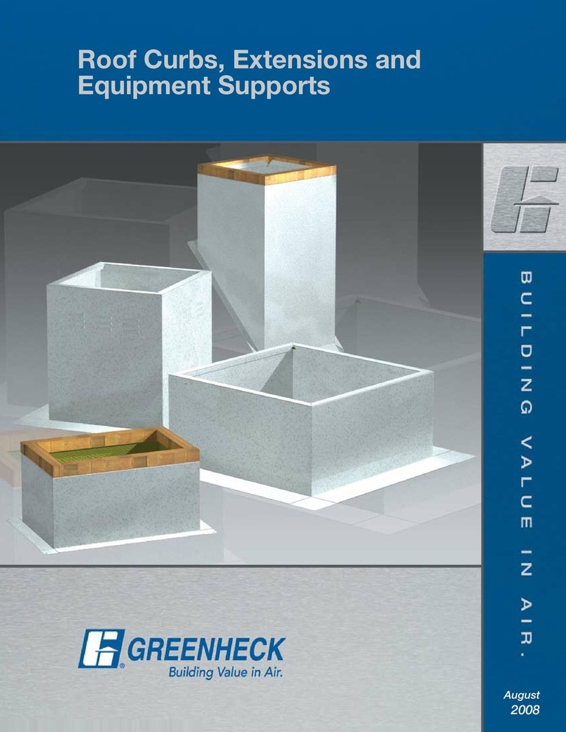
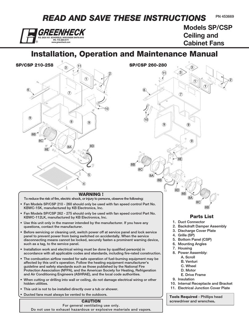
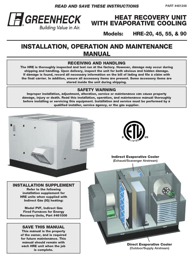
Greenheck MPX Installation instructions

P.O. Box 410
Schofield, WI 54476
Phone: 715.359.6171
www.greenheck.com
PRODUCT SPECIFICATION GUIDE
MODEL MPX –MAKE-UP AIR WITH PACKAGED COOLING AND HEATING
FACILITY SERVICES SUBGROUP: DIVISION 23 SECTION 74 33 XX
************************************************************************************************************************
Specifier Notes: This product specification guide is written in accordance to the Construction
Specifications Institute (CSI) Format - 2004 Edition.
This section must be carefully reviewed and edited by the Engineer to meet the requirements of the
project and local building code. Coordinate with other specification sections and the drawings.
Delete all unnecessary “Specifier Notes” when editing this section.
Note to User: This document is subject to copyright protection and is proprietary to Greenheck Fan
Corporation. However, Greenheck Fan Corporation authorizes the user a limited non-exclusive license to
use this document or portions of it for the purpose of preparing written product specifications for the
above CSI MasterFormat category. All information in this document as provided by Greenheck Fan
Corporation is informational in nature and is provided without representation or warranty of any kind as to
the user or any other party, including, without limitation, ANY IMPLIED WARRANTY OF
MERCHANTABILITY, FITNESS FOR PARTICULAR PURPOSE, OR NON-INFRINGEMENT. To the
greatest extent permitted by applicable law, Greenheck Fan Corporation assumes no liability, and User
assumes all liability and risk, for the use or results from the use of this document or the information
contained herein, whether as modified by the user or not. Users should consult www.greenheck.com to
verify that this document represents the most current version.
Instructions to A / E are shown in red. All such instructions are to be deleted by user.
Product options that must be selected are indicated in [brackets] in a list form. Make selection as
desired and then delete non-applicable elements.
************************************************************************************************************************
PART 1 - GENERAL
1.1 RELATED DOCUMENTS
A. Drawings and general provisions of the contract, including general and supplementary
conditions of Division 1 and portions of Division 22 (Plumbing), apply to this section. Insert
other applicable divisions here - Electrical(?)
1.2 SUMMARY
A. This section includes Packaged Outdoor Heating and Cooling Makeup Air-Conditioners with
Packaged DX for choose one [rooftop installation][outdoor installation on a concrete slab].
Within this document, these units may be referred to as Makeup Air Unit (MAU) for brevity.
Each unit shall have [digital] hermetic, scroll-type compressors as a primary cooling source
and shall provide 100% outdoor air to the space. [Each MAU shall be equipped with [an
indirect gas-fired furnace][an electric heater]]. Additional product requirements for each unit
shall be listed in Section 2 of this specification. If unit is intended for installation on a
concrete slab, verify design requirements and construction responsibility for the slab.
Specify that Supply Air must be end discharge.

B. Related sections include the following:
1. Division 01 General Requirements
2. Division 22 Plumbing
3. Division 23 Heating, Ventilating and Air Conditioning (HVAC)
4. Division 26 Electrical
Include any other applicable specification divisions.
1.3 SUBMITTALS (This section should include all data needed by A / E to verify suitability of
product for each application. As a minimum, it should include CAPS data and IOM).
A. Product Data: For each type or model of Packaged Outdoor Heating and Cooling Makeup
Air-Conditioner with Packaged DX, include the following:
1. Complete fan performance curves for Supply Air with system operating conditions
indicated, as tested in an AMCA Certified Chamber.
2. Sound performance data for Supply Air fan, as tested in an AMCA Certified
chamber.
3. AHRI Certified coil performance ratings with system operating conditions indicated.
Ratings shall be in accordance with Standard 410.
4. Motor ratings, electrical characteristics and motor and fan accessories.
5. EER Combined efficiency data per AHRI Standard 365.
6. Material types and gauges of all component pieces and assemblies.
7. Dimensioned drawings for each type of installation, showing isometric and plan
views, to include location of attached ductwork and service clearance requirements.
8. Estimated gross weight of each installed unit.
9. Installation, Operating and Maintenance manual (IOM) for each model.
10 Microprocessor Controller specifications to include available options and operating
protocols. Include complete data on all factory-supplied input devices. If MAU is to
be controlled by a BMS, verify compatibility of operating protocol. See also:
“Operating Protocol” in this document.
11. [Electric consumption data and construction specifications for electric heater, to
include heat output, warranty and safety certifications]
12. [Color chart including a palette of available standard paint finishes].
1.4 QUALITY ASSURANCE
A. Source Limitations: Obtain Packaged Outdoor Heating and Cooling Makeup Air-Conditioner
with Packaged DX with all appurtenant components or accessories from a single
manufacturer.
B. Product Options: Drawings must indicate size, profiles and dimensional requirements of
MUA Units and are to be based on the specific system indicated. Refer to Division 1 Section
“Product Requirements”.
C. Certifications
1. Blowers shall be AMCA Certified.
2. Entire unit shall be ETL Certified per U.L. 1995 and bear an ETL sticker.
3. Coils shall be Recognized Components for ANSI/UL 1995, CAN / CSA C22.2 No
236.05. DX coils shall be AHRI Certified per standard 410-2001.
D. [Indirect gas-fired furnace shall be ETL Certified as a component of the MUA][Indirect gas-
fired furnace shall be an ETL Recognized Component of the MUA per ANSI Z83.8]
1.5 COORDINATION
A. Coordinate size and location of all building penetrations required for installation of each
Makeup Air Unit and associated plumbing and electrical systems.
B. [Coordinate location of condensate drain system fittings to ensure correct positioning and
drainage].
C. Coordinate sequencing of construction of associated plumbing, HVAC, electrical
supply.[roofing contractor]
Product Specifications: Packaged Outdoor Heating and Cooling Make-Up Air Conditioners with Packaged DX (08/10) Page 2 of 7
Copyright © 2010 Greenheck Fan Corporation

1.6 EXTRA MATERIALS
A. Furnish extra materials described below that match products installed and that are packaged
with protective covering for storage and identified with labels describing contents.
Filters: [Insert quantity and MERV 8, 2 inch thick MERV 13, 4 inch thick MERV 13 or MERV
15] set(s) of disposable filters for each MakeUp Air Unit. When MERV 13 or MERV 15 filters
are specified, they are used in conjunction with MERV 8 pre-filters for Supply Air.
PART 2 – PRODUCTS
2.1 MANUFACTURERS
A. Available Manufacturers: Subject to compliance with specifications contained within this
document, manufacturers offering products that may be incorporated into the work include,
but are not limited to:
1. Greenheck
2.2 MANUFACTURED UNITS Indicate major components that must be included as part of the
unit.
A. Packaged Outdoor Heating and Cooling Makeup Air-Conditioners with Packaged DX shall
be fully assembled at the factory and consist of an insulated metal cabinet [with engineered
curb kit], [outdoor air intake hood [with bird screen][with aluminum mesh filter][motorized
intake damper] filter assemblies for intake air, evaporator coil, condenser coil(s), [digital]
scroll type compressor(s), engineered P trap assembly with P trap][modulating hot gas
reheat coil][electric post heater for auxiliary electric heat]supply air blower assembly,
[indirect gas-fired furnace] and electrical control unit with all specified components and
internal accessories factory installed and tested and prepared for single-point high voltage
connection. Entire unit with the exception of external components shall be assembled and
test operated at the factory.
2.3 CABINET Items A through J apply to all units. Items K through R are optional and may
vary. If more than one MAU is being ordered and they are not identical, then items K
through T should be annotated to show which units they apply to.
A. Materials: Formed, insulated double wall construction, fabricated to permit access to internal
components for maintenance.
1 Outside casing: 18 gauge, galvanized (G90) steel meeting ASTM A653 for
components that do not receive a painted finish. Components that receive a painted
finish per A / E specification shall be of 18 gauge type A60 galvannealed steel and
shall be painted with a baked industrial enamel finish. Specify finish: galvanized,
pre-painted Permatector or baked enamel.
2. Internal assemblies: [prepainted 18 gauge galvannealed steel][18 gauge, galvanized
(G90) steel] [baked enamel paint] except for motor supports which shall be 14
gauge galvanized (G90) steel.
B. Cabinet Insulation: Comply with NFPA 90A and NFPA 90B and erosion requirements of UL
181.
1. Materials: Fiberglass insulation. If insulation other than fiberglass is used, it must
also meet the Fire Hazard Classification shown below.
a. Thickness: 2 inch (25 mm)
b. Fire Hazard Classification: Maximum flame spread of 25 and smoke developed
of 50, when tested in accordance with ASTM C 411.
c. Location and application: Full coverage of entire cabinet exterior to include
walls, roof and floor of unit. Insulation shall be of semi-rigid type and installed
between inner and outer shells of all cabinet exterior components.
C. Access panels / doors: Unit shall be equipped with insulated, hinged doors or removable
access panels to provide easy access to all major components. Doors and access panels
shall be fabricated of 18 gauge galvanized G90 steel or painted galvannealed steel.
D. Condensate drain pan: Pan shall be formed of welded austenitic stainless steel sheet
material and provided with a welded drain connection at the front for connection to a P trap.
Drain pan shall be sloped in two directions to provide positive draining.
Product Specifications: Packaged Outdoor Heating and Cooling Make-Up Air Conditioners with Packaged DX (08/10) Page 3 of 7
Copyright © 2010 Greenheck Fan Corporation

E. P trap: An engineered P trap (condensate drain) assembly shall be provided for each unit, to
include cleanout ports, cleanout tool, vacuum break device and see-through reservoir to
permit visual verification of water or glycol solution levels.
F. Evaporator Coil: Evaporator coil shall be AHRI Certified and shall be (silver) soldered or
brazed into the compressed refrigerant system. Coil shall be constructed of copper tubing,
permanently bonded to aluminum fins and enclosed in a galvanized steel frame. If two
compressors are used as components of the MAU, then the evaporator coil shall be of
“interlaced” configuration, permitting independent operation of either compressor without
conflict with the other compressor.
G. Supply Air blower assemblies: Blower assembly shall consist of an electric motor as
specified by A / E and a belt driven blower. Assembly shall be mounted on heavy gauge
galvanized steel rails and further mounted on [1.125 inch thick neoprene vibration
isolators][spring-type vibration isolation devices (combination helical coil spring with
neoprene support cup)].
I. Control panel / connections: Makeup Air Unit shall have an electrical control center where all
high and low voltage connections are made. Control center shall be constructed to permit
single-point high voltage power supply connections. [Electric heater shall have a separate
electrical control center and separate high voltage power circuit as shown on the plans.]
J. Packaged DX System: Makeup Air Unit shall have an integral compressor(s) and evaporator
coil located within the weather-tight unit housing. Condenser coils and appurtenant
condenser fan assemblies shall be factory installed as integral subassemblies of the MAU
and mounted on the exterior of the MAU. Condenser fan motors shall be three phase, type
56 frame, Open Air Over and Shaft Up. Each condenser fan motor shall have a vented
frame, rated for continuous duty and be equipped with an automatic reset thermal protector.
Motors shall be UL Recognized and CSA Certified.The refrigerant compressor(s) shall be
[digital] hermetic scroll-type and shall be equipped with liquid line filter drier, thermal
expansion valve (TXV), manual reset high pressure and low pressure cutouts and all
appurtenant sensors, service ports and safety devices. Compressed refrigerant system shall
be fully charged with R-410A refrigerant. Each compressor shall be factory-equipped with an
electric crankcase heater to boil off liquid refrigerant from the oil. The use of an electric
crankcase heater is an essential unit-protective device in most climates. See IOM,
Subassembly Description. [Hot gas bypass shall be provided on the lead circuit to prevent
icing of the evaporator coil under low load conditions.] Hot gas bypass is not used with
digital scroll compressors.
Packaged DX Control and Diagnostics: The Packaged DX system shall be controlled by an
onboard digital controller (DDC) that indicates both owner-supplied settings and fault
conditions that may occur. The DDC shall be programmed to indicate the following faults:
Global alarm condition (active when there is at least one alarm)
Supply Air Proving alarm
Dirty Filter Alarm
Compressor Trip alarm
Compressor Locked Out alarm
Supply Air Temperature Low Limit alarm
•Sensor #1 Out of Range (outside air temperature)
•Sensor #2 Out of Range (supply air temperature)
•Sensor #3 Out of Range (cold coil leaving air temperature)
Product Specifications: Packaged Outdoor Heating and Cooling Make-Up Air Conditioners with Packaged DX (08/10) Page 4 of 7
Copyright © 2010 Greenheck Fan Corporation

Following are optional features, select as needed
K. [Reheat coil with factory installed modulating hot gas reheat valve]The reheat coil is for
humidity control and is connected to the compressor.
L. [Optional electric heater:] Electric heater shall be SCR control and shall be controlled by the
microprocessor controller. It shall include a temperature sensor with field adjustable set
point, located in the outdoor air stream after the heater. Heat output of the post-heater shall
be infinitely variable. Electric heater size / capacity shall be as specified by A / E.
M. [Optional indirect gas furnace]
- Shall be ETL Certified as a component of the Makeup Air Unit.
- Shall be constructed and configured to use [natural gas][LP gas].
- Shall have an integral exhaust gas blower
- Shall be ETL Certified for installation downstream of a cooling coil.
- Shall have 4-pass tubular heat exchangers, constructed of [aluminized steel][stainless
steel]
- [Shall be controlled by a microprocessor controller]
- Shall be encased in a weather-tight metal housing with intake air vents. Large, insulated
metal lift-off or hinged door shall provide easy access to the enclosed vest plate, control
circuitry, burner train, burner assembly and exhaust blower.
N. [Factory installed motorized damper for Intake Air shall be of low leakage type.]
O. [Dirty Filter Switch]
P. [Fire Stat Type III]
Q. [120V / 24V Smoke Detector]
R. Sensors are considered to be part of various optional operational modes or device
controllers and are to be factory supplied and installed as specified by the A / E. See IOM /
Sensors Installed by Factory
S. [Curb Assembly:] A curb assembly made of 14 gauge galvanized steel shall be provided by
the factory for assembly and installation as part of this division. The curb assembly shall
provide perimeter support of the entire energy recovery unit and shall have duct adapters for
Supply Air. Curb assembly shall enclose the underside of the unit and shall be sized to fit
into a recess in the bottom of the MAUt. Contractor shall be responsible for coordinating with
roofing contractor to ensure curb unit is properly flashed to provide protection against
weather/moisture penetration. Contractor shall provide and install appropriate insulation for
the curb assembly.
T. [Service outlet] 120 VAC GFCI service outlet shall be factory-provided and installed by this
contractor in a location designated by the A / E.
2.4 BLOWER SECTION
A. Blower section construction, Supply Air: Belt drive motor and blower shall be assembled on
a 14 gauge galvanized steel platform and shall be equipped with [1.125 inch thick neoprene
vibration isolation devices][spring type vibration isolation] devices.
B. Blower assemblies: Shall be statically and dynamically balanced and designed for
continuous operation at maximum rated fan speed and horsepower.
C. Fan: Airfoil plenum fan statically and dynamically balanced, AMCA certified for air and sound
performance, mounted on ground and polished steel fan shafts with ball bearing pillow
blocks. Bearings shall be selected for a minimum L10 life in excess of 50,000 hours at
maximum cataloged speeds.
D. Blower section motor source quality control: Blower performance shall be factory tested for
flow rate, pressure, power, air density, rotation speed and efficiency. Ratings are to be
established in accordance with AMCA 210, “Laboratory Methods of Testing Fans for Rating”.
Product Specifications: Packaged Outdoor Heating and Cooling Make-Up Air Conditioners with Packaged DX (08/10) Page 5 of 7
Copyright © 2010 Greenheck Fan Corporation

2.5 MOTORS
General: Condenser fan motors shall be as described above (Section 2.3, subsection J). Blower
motor shall be energy-efficient [ODP][TEFC]and comply with EPACT standards for single speed
ODP and TE enclosures. Motor shall be heavy-duty, permanently lubricated type to match the fan
load and furnished at the specified voltage, phase and enclosure. Drives shall be sized for a
minimum of 150% of driven horsepower and pulleys shall be fully machined cast-type, keyed and
fully secured to the fan wheel and motor shafts. Electric motors of ten horsepower or less shall be
supplied with an adjustable drive pulley. Comply with requirements in Division 23 05 13, matched
with fan load. Motors shall be Select one [60 cycle, 3 phase 208 volts] ,60 cycle, 3 phase 230
volts] [60 cycle, 3 phase 460 volt].
2.7 UNIT CONTROLS: Other than when a unit is retrofitted into an existing building control system or
otherwise configured to be controlled by an owner-supplied building controller, the MAU must be
ordered with a microprocessor controller. See IOM / Controls The MAU shall be constructed so
that it can function as a stand-alone cooling system controlled by factory-supplied controllers,
thermostats and sensors or it can be operated as a cooling system controlled by a Building
Management System (BMS). This Makeup Air unit shall be controlled by a factory-installed
microprocessor programmable controller that is connected to various optional sensors that may
have either analog or digital output.
1. A Microprocessor Controller known as a DDC shall be capable of receiving and
amplifying either digital or analog inputs from internal sensors or from a BMS. The
DDC shall be equipped with a large LCD display showing operating states, owner
specified settings and alarm conditions. Owner-specified ventilating conditions can
be input by means of pushbuttons. [RoomTemperature sensors][DDC Remote
Interface (room display)] The DDC shall have 4 MB flash memory capacity, pre-set
for a programming key, shall be modem/modem GSM/SMS ready, have 5 analog
inputs, 2 PT1000 inputs, 3 each 0 to 10 VDC inputs, 3 each 0 to 20 ma inputs, 5
NTC inputs, 3 each 0 to 5 VDC ratiometric inputs, AIN setting by software, 8 digital
inputs, 2 contact points, 8 each 24 VDC/VAC inputs, 4 analog outputs, 8 each
digital outputs, 7 SPST relay outputs, 1 SPDT relay outputs and 2 SSR outputs.
2. Operating protocol: The DDC shall be factory-programmed for (LonWorks][BACnet
MSTP][BACnet IP][Modbus]. Specify protocol.
3. [Variable Frequency Drive (VFD)][MAU shall have factory installed variable
frequency drive for modulation of the Supply Air blower assembly
The following devices are all optionally available for installation in the field. For
further information on specific devices, see the IOM: Field installed Control Sensors
4. [DDC Room Interface: Contractor shall provide and install Indicate quantity room
display(s) that function as remote indicators of owner-selected operating
parameters and also permit remote input of new operating parameters. Each room
display unit shall have a large LCD user interface screen similar in form and
function to the screen on the DDC. Installed location of room display(s) shall be as
indicated on the plans.] Note: only one room display per MUA is available.
5. [Dehumidistat: Contractor shall provide and install a dehumidistat as indicated on
the plans.]
6. [Room / Space Temperature Sensors: Contractor shall provide and install a room
temperature sensor as indicated on the plans]
7. [Dirty filter sensor]
8. [CO2 Sensor: Contractor shall provide and install a CO2 sensor as indicated on
the plans]
9. [Fire Stat Type III: Contractor shall provide and install a Type II Fire Stat as shown
on the plans]
10. [Industrial Remote Panel: Contractor shall provide and install a remote panel that
displays unit operating conditions and has enabling switches for system functions.
Remote panel is to be installed as shown on the plans. [Remote panel shall have a
DDC Room Display built in to provide for remote inputting of operating
parameters]]See IOM: Field Installed Control Sensors / Remote Operating Panel.
Product Specifications: Packaged Outdoor Heating and Cooling Make-Up Air Conditioners with Packaged DX (08/10) Page 6 of 7
Copyright © 2010 Greenheck Fan Corporation
Product Specifications: Packaged Outdoor Heating and Cooling Make-Up Air Conditioners with Packaged DX (08/10) Page 7 of 7
Copyright © 2010 Greenheck Fan Corporation
11. [Duct-mounted Smoke Detector]
2.8 FILTER SECTION: Makeup Air Unit shall have permanent metal filters located in the outdoor air
intake and shall be accessible from the exterior of the unit. [MERV 8] [Combination of MERV 8 and MERV
13] [combination of MERV 15 and MERV 8]pleated filters shall be provided in the intake air stream.
PART 3 – EXECUTION
3.1 EXAMINATION
A. Prior to start of installation, examine area and conditions to verify correct location for
compliance with installation tolerances and other conditions affecting unit performance. See
unit IOM.
B. Examine roughing-in of plumbing, electrical and HVAC services to verify actual location and
compliance with unit requirements. See unit IOM.
C. Proceed with installation only after all unsatisfactory conditions have been corrected.
3.2 INSTALLATION: Installation shall be accomplished in accordance with these written
specifications, project drawings, manufacturer’s installation instructions as documented in manufacturer’s
IOM, Best Practices and all applicable building codes.
3.3 CONNECTIONS: In all cases, industry Best Practices shall be incorporated. Connections are to
be made subject to the installation requirements shown above.
A. Piping installation requirements are specified in Division 22 (Plumbing). Drawings
indicate general arrangement of piping, fittings and specialties. This pertains to installation of a
condensate drain.
B. Duct installation and connection requirements are specified in Division 23 of this
document.
C. Electrical installation requirements are specified in Division 26 of this document.
3.4 FIELD QUALITY CONTROL
A. Manufacturer’s Field Service: Engage a factory authorized service representative to inspect
field assembled components and equipment installation, to include electrical and piping
connections. Report results to A / E in writing. Inspection must include a complete startup
checklist to include (as a minimum) the following:
3.5 STARTUP SERVICE
A. Engage a factory authorized service representative to perform startup service. Clean
entire unit, comb coil fins as necessary, install clean filters. Verify water source for
compliance with manufacturer’s requirements for flow and temperature. Measure and
record electrical values for voltage and amperage. Refer to Division 23 “Testing,
Adjusting and Balancing” and comply with provisions therein.
3.6 DEMONSTRATION AND TRAINING: Engage a factory authorized service representative to train
owner’s maintenance personnel to adjust, operate and maintain the entire energy recovery unit.
Refer to Division 01 Section Closeout Procedures and Demonstration and Training.
End of Section 23 74 33.XX
Table of contents
Other Greenheck Air Conditioner manuals

Greenheck
Greenheck SP 210-258 User manual

Greenheck
Greenheck DGX User manual

Greenheck
Greenheck ERCH-20 User manual

Greenheck
Greenheck HRE-20 User manual

Greenheck
Greenheck HRE-20 User manual

Greenheck
Greenheck ATI User manual

Greenheck
Greenheck IG-100 Installation and operating instructions

Greenheck
Greenheck DFD Series User manual

Greenheck
Greenheck EHH-601D User manual

Greenheck
Greenheck ESD-635D User manual