Sure-Aire™ Flow Monitoring System4
Air Flow Units: Press “Edit” to change Air Flow Units.
Press “Prev” or “Next” to adjust, then press Enter to
store the value.
• CFM (default)
• m³/hr
• m³/min
Pressure Units: Press “Edit“ to change pressure units.
Press “Prev“ or “Next“ to adjust, then press “Enter“ to
store the value.
• In. wg (default)
• Ft wg
• mm wg
• cm wg
• PSI
• In. Hg
• mm Hg
• mBar
• Pa
• kPa - kilopascals (1kPa = 1000 Pa)
• hPa - hectopascals (1hPA = 100 Pa)
• Oz. In.
Temperature Compensation: Press “Edit“ to change
Temperature Compensation. Press “Prev“ or “Next“ to
adjust, then press “Enter“ to store the value.
• Yes (default)
• No
Note: If temperature compensation is set to “No“, the
air density will be a function of standard temperature
(70°F / 21°C).
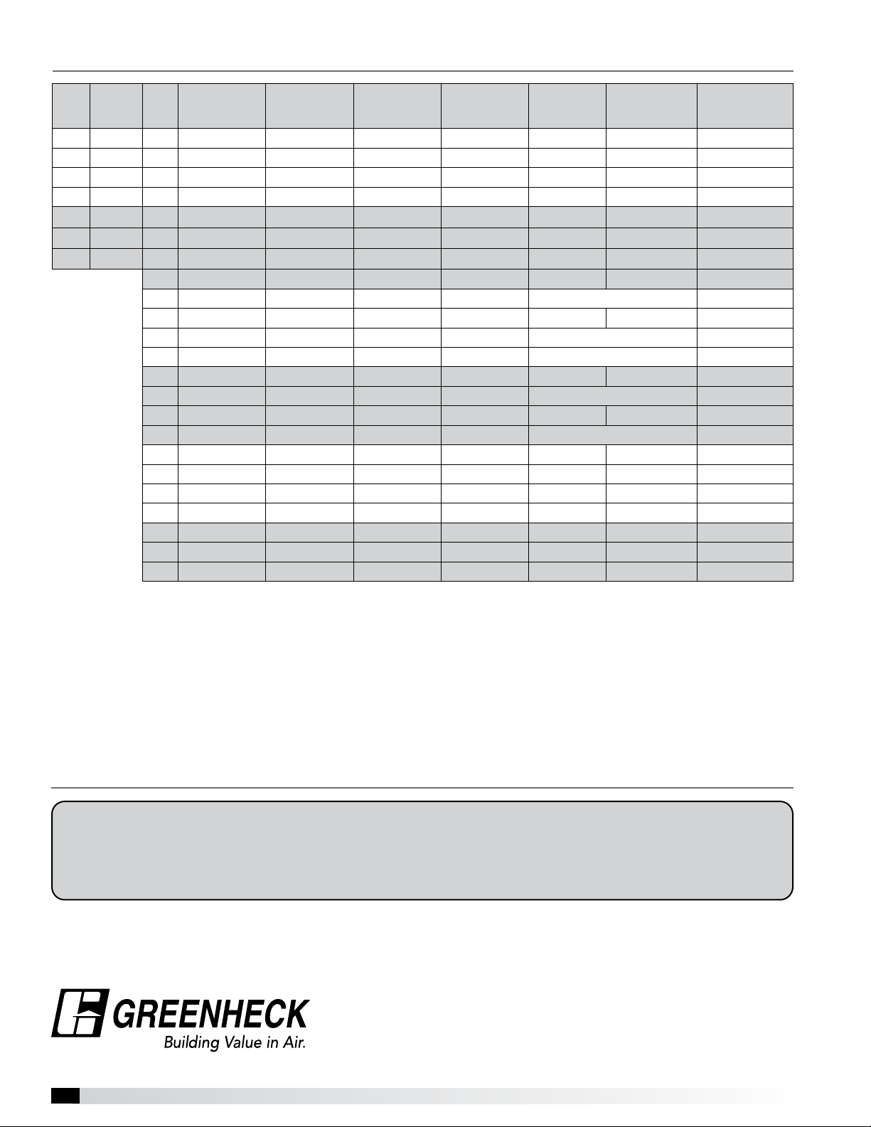
Analog Output Signal: Press “Edit“ to change Output
Signal type. Press “Prev“ or “Next“ to adjust, then press
“Enter“ to store the value.
• 4-20 mA (default)
• 2-10 VDC
Linearize By: Press “Edit“ to change the linearization
settings. The electronics will linearize the electronics
output with respect to this setting.
• Flow (default)
• Pressure
Note: The maximum measurable flow rate will
automatically calculate based on the electronics
settings. The maximum flow rate is displayed on the
screen.
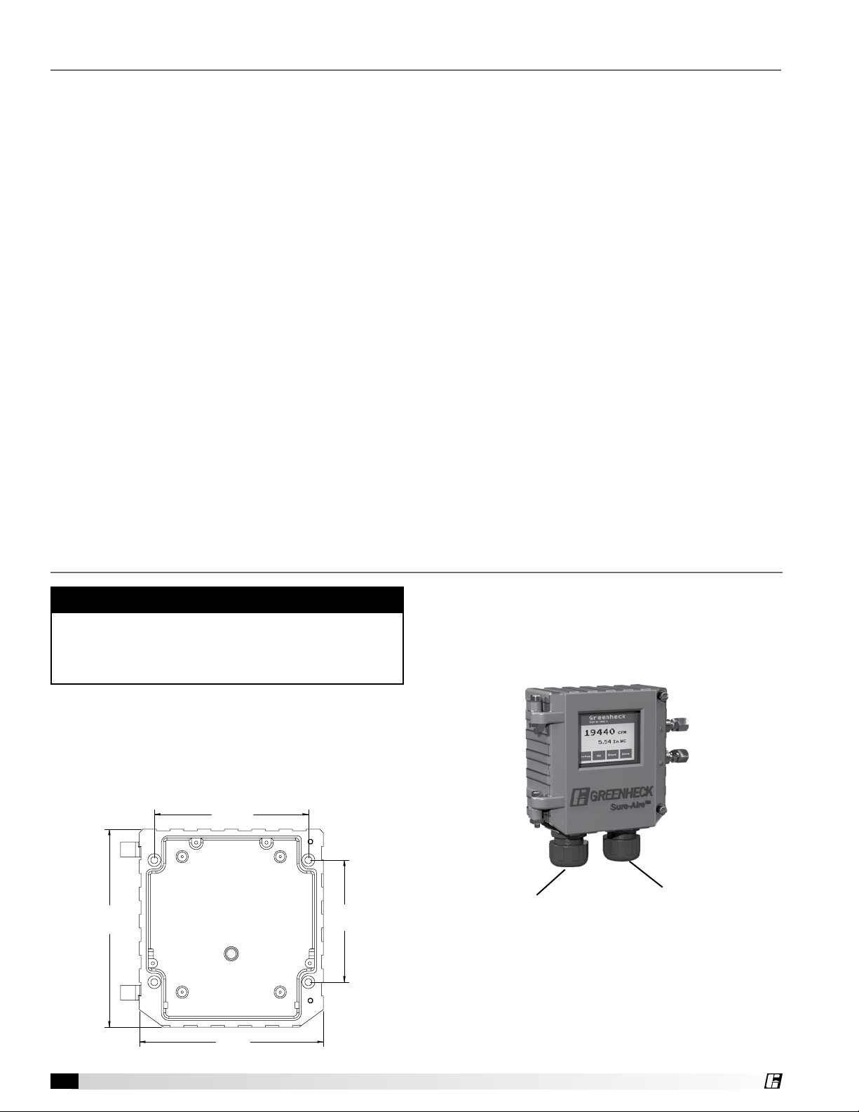
Navigation Buttons
The electronics is equipped with a touchscreen LCD
display. There are 4 navigation buttons on the bottom
of the screen. Button names will change based on the
parameter you are in (i.e. “Setup” will change to “Home”
and “Home” will change to “Edit”).
Home Screen
To view the different settings use the “Up” and “Down”
buttons to scroll through the list. To adjust settings,
press “Setup” and scroll through the settings. Below is
information on the adjustable settings.
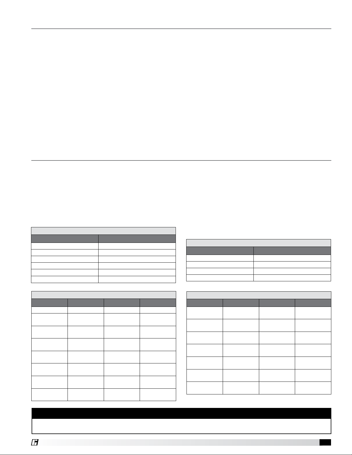
Settings Menu
Home Screen: Top/Bottom View: Press “Edit“ to
change Main Display Value. Press “Prev“ or “Next“ to
adjust what reading displays on the Home screen, then
press “Enter“ to store the value.
• Flow (default)
• Pressure
• Temperature
• Air density
• Output signal (default bottom display)
• Velocity
• None
Measurement System: Press “Edit“ to change the
measurement system units. Press “Prev“ or “Next“ to
adjust, then press “Enter“ to store the value.
• English (default)
• Metric
K-Factor: Press “Edit“ to change K-Factor. Press “Inc“
or “Dec“ to adjust, then press “Enter“ to store the value.
• 200 to 30,000
Elevation: Press “Edit“ to change elevation. Press “Inc“
or “Dec“ to adjust, then press “Enter“ to store the value.
• 0 - 10,000 ft
(0 ft default)
Outlet Area: Press “Edit“ to change the stack outlet
area. Press “Inc“ or “Dec“ to increase or decrease the
area, respectively. Then press “Enter“ to store the value.
• 0-10 Ft²
Display Brightness: Press “Edit“ to change brightness.
Press “Inc“ or “Dec“ to adjust, then press “Enter“ to
store the value.
• 10 - 100%
(80% default)
Greenheck
Sure-Aire V 2.00
0.0010 CFM
3.96 mA
Setup Up Down Home
Display Setting Options and Setup
WARNING
Due to load resistance change from product to
product, it may be necessary to recalibrate the
4-20mA electronics. See 4-20 mA transducer
calibration procedure.