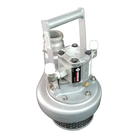
H4660B / 42190 Submersible Pump
Greenlee / A Textron Company 74455 Boeing Dr. • Rockford, IL 61109-2988 USA • 815-397-7070
Assembly (cont’d)
11. If pipe plug (17) was removed, reinstall plug
in rear cover and torque to 41 to 54 Nm
(30 to 40 ft-lb).
12. Install Woodruff key (10) in drive shaft (14).
13.
Turn drive shaft. Drive shaft must turn without binding.
Motor Test Procedure
Note: The test stand should contain hydraulic fluid
maintained at a temperature of 46 - 52
°
C (115 - 125
°
F).
See Recommended Hydraulic Fluids in Specifications
and Parts.
1. Plug return (T) port of motor.
2. Connect pressure line of hydraulic power source
to pressure port (P) of motor.
3. Start hydraulic power source and supply 19 l/min @
137.9 bar (5 gpm @ 2000 psi) to motor. Motor must
not have any leakage.
Motor Break-In Procedure
Note: Motor break-in is required only if any worn internal
components were replaced with new components.
Note: Before connecting hoses, see Specifications
and Parts List for power source specifications. Install a
100-mesh screen at motor inlet port. Install a 0 - 35 bar
(0 - 500 psi) pressure gauge in the return line.
1. Connect pressure and return lines of hydraulic
power source to appropriate pressure (P) and return
(T) ports of motor.
2. Start hydraulic power source and supply 19 l/min @
137.9 bar (5 gpm @ 2000 psi) to motor. Run motor
for three minutes. Motor must not have any leakage.
Motor, Motor Adapter and Handle
1. Install two bearings (8) on shaft (7) and secure using
external retaining ring (9). Slide shaft with bearings
into motor adapter (5) and secure using internal
retaining ring (10).
Note: Pumps manufactured since 1993 have motor
adapter (5) that requires an O-ring (32).
• If your adapter has an O-ring groove, install the
O-ring (32).
• If your adapter does not have an O-ring groove,
clean mating surfaces of motor and housing with
Loctite
®
755-59 Safety Solvent, or equivalent.
Coat one surface evenly with silicon sealer and
allow ten minutes to dry before assembling.
2. Install complete motor assembly (17) in motor
adapter (5). Make sure Woodruff key in motor drive
shaft slides into slot of shaft (7) in motor adapter.
Secure motor to motor adapter (5) with two hex head
cap screws (18) and lock washers (15). If handle
(19) was removed, install on motor adapter (5) and
secure with two hex head cap screws (20) and lock
washers (21).
Motor (cont’d) Impeller Clearance
1. Slide shim (12) onto end of shaft (7). Install Woodruff
key (11) in keyway of shaft (7). Slide impeller (13)
onto shaft, guiding keyway in impeller over the
Woodruff key in shaft.
2. Lock impeller (13) in place by placing an appropriate
diameter hardened rod, approximately 4 mm (.171"),
in one of the small holes in impeller and mating the
rod with hole in motor adapter (5). If no rod is
available, place a screwdriver between blades of
impeller. Secure impeller to shaft with jam nut (14).
3. Check clearance between impeller (13) and motor
adapter (5). The clearance between these compo-
nents should be 0.5 - 1 mm (.020 - .044"). Add or
remove shim(s) (12) between impeller (13) and shaft
(7) as needed to achieve proper clearance.
4. To set impeller/housing clearance, install six (brown)
gasket shims (4) on motor adapter (5), and set motor
and motor adapter subassembly on housing. Begin
removing gasket shims (4) until there is interference
between the impeller (13) and housing (1). When an
interference is achieved, add one gasket shim, either
the (blue) gasket shim (3) or a (brown) gasket shim
(4), whichever one achieves a minimum clearance
without impeller/housing interference.
5. After setting impeller clearance, secure motor
adapter (5) to housing (1) by installing six hex nuts
(16), lock washers (15) and flat washers (30) on
studs protruding up from mounting holes in motor
adapter (5).
Inlet Screen (Strainer)
1. Install six hex head cap screws (27), with lock
washers (28) and flat washers (29) into sub base
(26). Position base so the threaded end of hex head
cap screws are pointing upwards.
2. Slide bushings (25) over hex head cap screws (27).
Snap inlet screen (strainer) (24) into groove in
base (26). Slide inlet (23) over hex head cap
screws (27), and snap groove in inlet (23) securely
onto inlet screen (strainer) (24).
3. Install strainer assembly on bottom of housing (1)
using six hex head cap screw (27). Tighten cap
screws securely.


