Greenspan SDI-12 User manual

SDI-12 Converter
4 - 20mA and RS232 Versions
User
Manual
Version 1.03

+61 7 4660 1888
Greenspan Customer Service
Technical Support When You Need It
The correct choice of sensor should be supported by professional advice to
ensure long term success in the field. Greenspan Technical Services is
dedicated to customer support and provides assistance in the selection,
installation, deployment and commissioning of sensors with a full range of
consulting services.
A full technical support and field advice service can be accessed by ringing
Customer Service on +61 7 4660 1888 between 8am - 6pm, 5 days a week.
All requests for information will be serviced within 24 hours.
All Greenspan products are designed, developed and manufactured in Australia,
can be supplied at short notice and be customised to meet most requirements.
Warranty Details
All Greenspan products are covered by a 12-month warranty.
All warranty service will be turned around in 7 working days or less or contact
will be made with customer to discuss delay.
The sensor should not be dismantled unless under instruction from Greenspan.
Incorrect handling will void the warranty.

Contents
1 INTRODUCTION
Overview...........................................................................…….… 1
2 THE HARDWARE
Converter Design......................................................................... 2
SDI-100 (4-20mA)...........................................................………... 2
SDI-200 (RS232, Smart))............................................................. 2
SDI-300 (RS232, Sonde)..........................................................…. 2
Power Requirement.....................................................………….. 3
3 COMMUNICATIONS PROTOCOL
SDI-12 Control Sequence....................................................……. 4
4 INSTALLATION
Electrical Bus Connection........................................................... 5
Wiring Connection to SDI-100................................................…. 6
Connection to SDI-200................................................................. 8
Connection to SDI-300................................................................. 8
General Installation...........................................................……... 8
5 TROUBLESHOOTING.................................................................………. 9
6 SPECIFICATIONS
SDI-100/200/300 Specification..................................................... 10
APPENDIX
Setup and Testing Example...................................................….. 11
Supported Converter Commands.....................………………….. 12

INTRODUCTION 1
Overview
The Greenspan SDI-12 Converter, model numbers SDI-100, SDI-200 and SDI-
300 are designed to allow connection of standard Greenspan sensors to the SDI-
12 serial/digital network widely used in the hydrological and field monitoring
industry.
SDI-12 allows multiple connection of sensors to a single data logging recorder,
transmitting at 1200 baud over distances up to 60 metres (200 ft) between each
converter unit and data logger.
Note that cable lengths from sensor to converter unit have been tested
up to 300 metres and are not subject to the SDI-12 limit of 60 metres.
The converter is packaged in a durable, robust, weatherproof housing and,
depending on the model, is either hardwired or uses cable connectors for sensor
connection and serial cable in/out. Power is supplied to the converters and
sensors via the SDI-12 cable from the data logger.
A Sensor Input
B SDI In
C SDI Out
D Sensor On Indicator
E Vent fitting (for pressure sensors)
SDI-100 Converter SDI-200/300 Converter
(for 4-20mA sensors) (for RS232 sensors)
A
B C
A
B
D
D
3
E E C
3
UM-010-0012-SDI-12 GREENSPAN TECHNOLOGY 1

HARDWARE 2
Converter Design
There are two basic models of SDI-12 converter, one for 4-20mA sensors and one
for RS232 sensors. A third variation allows for connection to Sondes.
SDI-100 (4-20mA)
The Greenspan SDI-100 converter consists of the following primary elements:
• Three cable entry/exit ports with weatherproof cable seals
• Microprocessor controlled signal conditioning and serial input/output
circuit
• ‘Sensor On’ indicator
• Weatherproof housing to IP65
• Vent fitting for desiccant packs, for use with gauge pressure sensors.
Any 4-20mA output sensor may be connected to this unit by simple screw
terminals within the housing. The analog signal (current loop) is converted to a
digital signal and output as SDI-12 format serial data.
SDI-200 (RS232 for Smart)
The Greenspan SDI-200 converter consists of the following primary elements:
• Three Conxall entry/exit connectors mounted on housing, SDI Out
includes weather cap protection if output not used.
• RS232 signal processing (microprocessor controlled) and serial
input/output circuit
• ‘Sensor On’ indicator
• Weatherproof housing to IP65
• Vent fitting for desiccant packs, for use with gauge pressure sensors
This model receives RS232 serial data and converts it to SDI-12 serial data
format. The sensors used with this converter include microprocessor and logging
capability, therefore data retrieval and control functions may be activated from
the remote SDI-12 logger. It is not necessary to open this unit as all connections
are external.
UM-010-0012-SDI-12 GREENSPAN TECHNOLOGY 2

SDI-300 (RS232 for Sonde)
The Greenspan SDI-300 converter is the same as the SDI-200 except for the
inclusion of a 31 pin Connector to suit the Sonde.
Power Requirement
All units require +9 to +15V DC power supplied to them from the data logger via
the network cable. The current drawn in standby mode is 10mA and less than
100mA (typically 40mA) per unit including sensor power, when reading
measurements. The maximum load on the bus must be less than 500mA.
Transient protection (against induced electromagnetic effects e.g., lightning) on
both the SDI-12 serial lines and the +12V line is provided on all units.
Supply polarity protection is provided by a polyfuse device and is auto resetting.
The design complies with EMC standards for radiation interference.
UM-010-0012-SDI-12 GREENSPAN TECHNOLOGY 3

COMMUNICATIONS PROTOCOL 3
SDI-12 Control Sequence
SDI-12 data loggers and sensors communicate by an exchange of ASCII
characters on the serial data line. The data logger sends a break to wake up the
sensors on the data line. A break is a continuous spacing on the data line for at
least 12 milliseconds. The data logger then sends a command. The sensor, in
turn, returns the appropriate response. Each command is for a specific sensor.
The first character of each command is a unique sensor address that specifies
which sensor the logger wants to communicate with. Other sensors on the SDI-
12 bus ignore the command and return to low-power standby mode. When a
data logger commands a sensor to start its measurement procedure, the logger
does not communicate with any other sensor until the data collection from the
first sensor is complete.
A typical recorder/sensor measurement sequence proceeds as follows:
Step 1. The data logger wakes all sensors on the SDI-12 bus with a break.
Step 2. The logger transmits a command to a specific, addressed sensor,
instructing it to make a measurement.
Step 3. The addressed sensor responds within 15 milliseconds and
returns the following information:
a) The maximum time before the measurement data is ready.
b) The number of data values it will return.
Step 4. If the measurement is immediately available, the logger transmits
a command to the sensor instructing it to return the
measurement(s). If the measurement is not ready, the data logger
waits for the sensor to send a request to the logger, to indicate
that it is ready. The logger then transmits a command to get the
data.
Step 5. The sensor responds, returning one or more measurements.
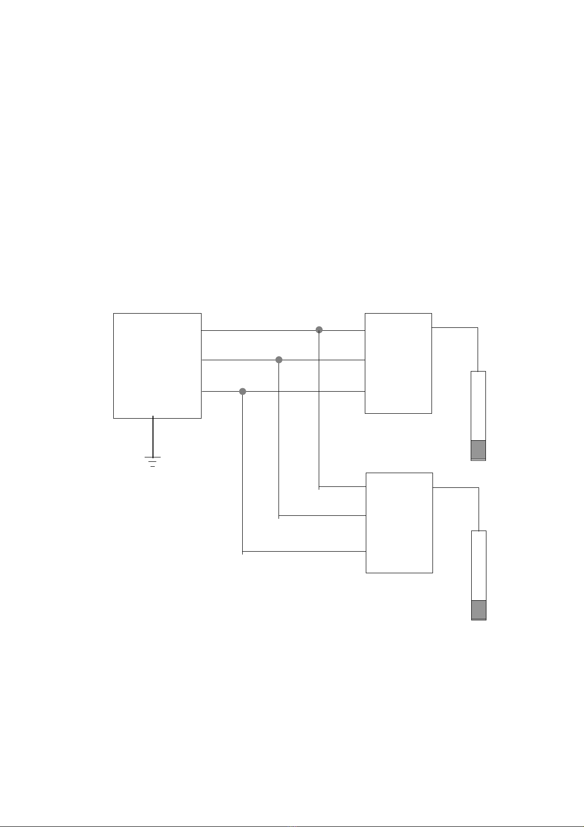
There is a maximum of nine addresses that can be accessed on the network and
these are numbered 00 to 09.
Note that it is possible to setup for dual logging if the sensor type is a
Greenspan Smart sensor with onboard logger. The SDI-12 data logger can
request readings at any time from the Smart sensor independently of the
readings being logged by the sensor.
UM-010-0012-SDI-12 GREENSPAN TECHNOLOGY 4

INSTALLATION 4
Electrical Bus Connection
The SDI-12 bus is the cable that connects multiple SDI-12 devices. This cable
has three conductors:
1 Ground Line
2 Serial Data Line
3 +12V Line
Figure 1 shows the SDI-12 bus connecting one data logger with two SDI-12
converter units and their sensors.
Serial Data Line
SDI-12
Data
Logger +12V Line
Ground Line
4-20mA
Sensor
SDI-200
Converter
SDI-100
Converter
Earth
RS232
Sensor
Figure 1, The SDI-12 Bus
The maximum load that may be applied to the SDI-12 bus is 200K ohms when
the transmitter is off and between 1K and 2K ohm when the transmitter is on.
The ground line must be connected to the circuit ground and the earth ground at
the data logger. The sensor ground must be connected to the ground line, but
not normally to its own ground.
UM-010-0012-SDI-12 GREENSPAN TECHNOLOGY 5

Wiring Connection to Model SDI-100
Connection to the SDI-100 is by internal terminal block as most sensors are
supplied with bare wire terminations suitable for data logger connection.
Please refer to Figure 2 for connection:
Sensor
Cable
SDI In SDI Out
Cable Clamp
SDI-100
Base
1 2 3 4
1. +12V, Red
2. Input 1, Blue
3. Input 2, White
4. Ground, Green
Note: Colours are for
Greenspan products
only.
1 2 3 1 2 3
1. Ground, Green
2. Serial Data, Blue
3. +12V, Red
Figure 2, SDI-100 Wiring
1. Undo four case screws and remove top cover.
2. Insert sensor cable through sensor port. For gauge type pressure sensors,
a vent tube is required to be fitted. The cable vent tube is cut and pushed
into joiner provided. The millipore filter attached to the vent tube for
shipping can be used on the SDI-100 if desiccant packs are not required.
Spare desiccant packs, (PVS100) are available from Greenspan for
attachment to Luer fitting. Please refer to figure 3.
UM-010-0012-SDI-12 GREENSPAN TECHNOLOGY 6

Luer fitting
gland
Loop 150mm
PVC Tube
20mm joiner
sensor vent tube
Figure 3, Vent Fitting
3. Refer to Figure 2 for connection and clamp wires to terminal block.
4. Insert remaining cables through SDI In port and SDI Out port (for
multiple connections any 4-6 mm OD, 3 core cable is suitable).
5. Refer to Figure 2 for connection to terminal block.
6. Tighten cable clamps on all three cable ports, replace top cover and
tighten screws.
UM-010-0012-SDI-12 GREENSPAN TECHNOLOGY 7

Connection to Model SDI-200
Connection to the SDI-200 is by external Conxall connectors. Smart Sensors are
normally supplied with 18 pin plugs for quick connection. Please refer to Smart
Sensor User Manual for pin connections. For network interconnection the
following cable is required:
SDI Out
Conxall 3 pin Cable Plug
Rear View
SDI In
Conxall 3 pin Cable Socket
Rear View
3
2 1
1
2
3
1 Ground
2 Serial Data
3 +12V
Figure 3, SDI Network Cable Connector Pin-out
Conxall 3 pin Cable Plug
Conxall 3 pin Cable Socket
Maximum Length = 60m
3 or 4 core, 5.5mm OD
Figure 4, SDI Network Cable
Connection to Model SDI-300
Connections are the same as for the SDI-200 with the exception that the unit is
fitted with a 31 pin Conxall connector to suit the Sonde and some internal links
are set at the factory. All other functions are the same.
General Installation
Ensure that cable lengths between units are no more than 60 metres (200ft).
One advantage of Greenspan external SDI-12 Converter units is that sensor
cable lengths can be much greater than the SDI-12 limit for installation in deep
bore holes and remote locations.
Consideration needs to be given to the possibility of vandalism, animal damage,
theft and extreme weather conditions.
UM-010-0012-SDI-12 GREENSPAN TECHNOLOGY 8

TROUBLESHOOTING 5
1. Cannot communicate with ANY of the converter units on the
network from the PC and SDI-12 data logger.
The cause of the problem will be with the PC/Data Logger and software setup
OR in the first section of SDI-12 cable from the Data Logger to the first device
on the network.
a). Check the cable connection between PC and Data Logger, is it the correct
RS232 cable for that logger. Are any pins bent?
b). Check that the PC COMM port (RS232 serial) has been selected
correctly.
c). If communication between the PC and logger is working, does the sensor
indicator on the converter turn on, if not, the problem is the connection
between the logger and the converter.
2. Cannot communicate with ONE of the sensors on the network from the
PC and SDI-12 data logger.
a). Check the power supply (greater than +12V?)
b). Check the current drain (quiescent current drain will be approximately
10mA per unit). Note that current drain increases significantly when
sensor is turned on and taking measurements (up to 100mA depending
on sensor type).
If the quiescent current drain (i.e. without PC connected or SDI-12 comms in
progress) is greater than 10mA then for SMART Sensors it is possible that the
SMART board has not returned to sleep mode. The SMART Sensor can be reset
by briefly removing power and re-powering.
3. Measurement Conversion Errors at SDI-12 logger.
For 4-20mA sensors connect a milliammeter in series with the current loop
output of the sensor and check for 4.00mA at zero and a known mA value for a
specific reference value at full scale or less. Refer to Sensor User Manual.
For RS232 sensors, run Smartcom and check readings in Monitor screen are
correct for the reference solutions. Refer to Sensor User Manual.
If sensor readings are correct and SDI-12 converted readings are different then
check:
a) If network cables are less than 60 metres between units, data loss may
occur if voltage drops and impedance is incorrect.
b) If converter is faulty; replace SDI-12 Converter unit with a known good
unit.
c) If channel settings are correct on data logger.
UM-010-0012-SDI-12 GREENSPAN TECHNOLOGY 9

SPECIFICATIONS 6
Specification Model SDI-100 Model SDI-200/300
Baud Rate 1200 baud 1200 baud
----------------------------------------------------------------------------------------------------------
Address Range 00 to 09 00 to 09
-----------------------------------------------------------------------------------------------------------
Input 4-20mA RS232
-----------------------------------------------------------------------------------------------------------
Output SDI-12 SDI-12
-----------------------------------------------------------------------------------------------------------
Supply Voltage 9-15VDC 9-15VDC
Reverse polarity protected and surge protected to 2kV
-----------------------------------------------------------------------------------------------------------
Standby Current 10mA 10mA
Comms Current 24mA 24mA
(The total current drawn from the network is dependent on sensor type and
number of units). Maximum limit is 500mA.
-----------------------------------------------------------------------------------------------------------
Response Time 15ms 15ms
-----------------------------------------------------------------------------------------------------------
Dimensions Length 115 mm Length 115 mm
Width 90 mm Width 90 mm
Height 55 mm Height 55 mm
-----------------------------------------------------------------------------------------------------------
Housing ABS moulded ABS moulded
plastic plastic
-----------------------------------------------------------------------------------------------------------
Output Load (transmit on) 1K ohms 1K ohms
2K ohms 2K ohms
Output Load (transmit off) 200K ohms 200K ohms
-----------------------------------------------------------------------------------------------------------
Storage Temperature -20 to +50°C -20 to +50°C
-----------------------------------------------------------------------------------------------------------
UM-010-0012-SDI-12 GREENSPAN TECHNOLOGY 10

APPENDIX
Specific instruction for setting up and testing of SDI-12 networks varies from
logger to logger. However, an example for Campbell type logger CR-10 is
included for reference.
Model SDI-200/300
Setup
•Install Campbell Logger software Tcom.exe.
•Connect Smart Sensor/Sonde as appropriate to sensor input connector on SDI
Converter.
•Connect RS232 cable to CS I/O, DB9 on Campbell logger and to Com2 port on
PC.
•Connect SDI-12 cable to SDI-IN socket on SDI-200 unit.
•Apply +12V power to Campbell logger.
•Run Tcom.exe and in Network Map select Com2 and CR10-2.
Testing
•Factory units are normally shipped set to 0.
•To change the converter address select Terminal mode on Campbell logger and
press space bar a few times until an acknowledge of ‘X’ is displayed:
Type: 2X press <enter>, wait until response is:
‘Entering SDI-12’
Type: 0A1! to change address from 0 to 1
(any number from 0-9 can be selected, note:
exclamation mark replaces enter key)
•To check address is correct :
Type: ?! response should be 1
•From View Menu select Datalogger Session. Press <Enter> and wait until
response is: ’Exiting SDI-12’
•Select Disconnect
•Select Monitor Tab (bottom of screen).
•Wait until LED on SDI-200/300 is off for the first time then select
Connect.
•The monitor screen will display a column of data values
In-LOC 1 Depth reading (e.g. 0.000, no pressure)
In-LOC-2 Temp Reading (e.g. 21.8 ambient)
•Check reading responds on screen. For a pressure sensor, apply a small
amount of finger pressure to sensor face for at least 30 seconds. Check reading
changes to a new value in LOC 1.
•Check that LED indicator is ON for 15 sec and Off for 15 seconds cycling.
This completes SDI-12 testing.
UM-010-0012-SDI-12 GREENSPAN TECHNOLOGY 11

UM-010-0012-SDI-12 GREENSPAN TECHNOLOGY 12
SUPPORTED CONVERTER COMMANDS
This table lists the commands supported by the Greenspan SDI-100 and SDI-
200/300 Converter units:
Command Function Notes
?! Address Query Fully Implemented
a! Acknowledge Active Fully Implemented
aI! Send Identification Fully Implemented
aAb! Change Address Fully Implemented
aD0! Send Data Fully Implemented
aM! Start Measurement Fully Implemented
aM1-9! Additional Measurements Valid reply but not applicable
aR0-9! Continuous Measurements Valid reply but not applicable
aV! Start Verification Resets data and returns 0001
aZ0-1???! Set Sensor Range *Sets sensor channel range*
Note: * Only applicable to SDI-100 4-20mA range setting, normally factory set.
Where a = sensor address, b = new address, ?is any digit or decimal and *
indicates that the command is not applicable to this sensor.
The sensor range is specified using the extended command ‘Z’ as follows:
0Z01000.00! sets the channel 0 range to 1000.00 assuming a sensor address
of 0.
0Z150.00! sets the channel 1 range to 50.00 again assuming a sensor address
of 0.
The first character after the extended command ‘Z’ is used to select the sensor
channel. Up to 7 characters may follow which must be digits or a decimal point.
These set the channel range.
The command is terminated with a ‘!’. Excessively large ranges are scaled back
but no other error checking is performed.
Table of contents