Selectone ST-146 User manual

Manual Number: M501-2855 April 19, 1996 Revision (960419-1)
GENERAL:
The ST-146 is a miniature surface-mount version of our popular
ST-104 CTCSS Encoder/Decoder it features a universal design for
easy interface to most radio squelch circuits, end is small enough
to be mounted in a mobile or portable radio where space is limited.
Like the ST-104, the ST-146 is fully compatible with all major
CTCSS systems, including Motorola "Private Line", General
Electric "Channel Guard", and E.F.Johnson "Call Guard".
Due to surface-mount construction and our comprehensive
warranty policy, field repair is usually not cost effective. Complete
technical documentation is available through our applications
department for customers with special requirements.
Application information is available or can be developed for most
radio models. If you would like application details for a specific
radio, please call us TOLL FREE at (800) 227-0376.
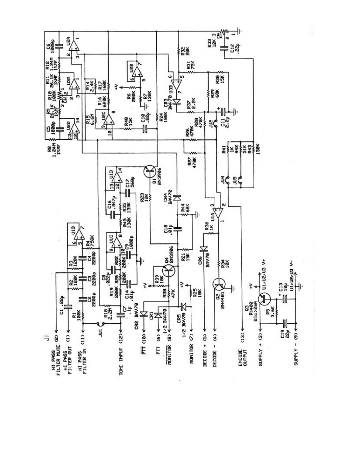
ADJUSTMENTS
Frequency:
The ST-146 is CONTINUOUSLY tuneable over the standard
CTCSS frequency range from 67 to 250.3 Hz. To set the
frequency, apply power, set R33 fully clockwise and connect the
Tone Output lead (WHT/GRN) to your frequency measuring
equipment Adjust R10 for the desired CTCSS frequency. You may
find the use of a lissajous figure with a known on-frequency
reference the quickest set-up procedure, or as an alternate if a
frequency counter is not available.
Output Level:
The Tone Output level is adjusted with R33. Adjust R33 for
approximately ±750 Hz deviation.
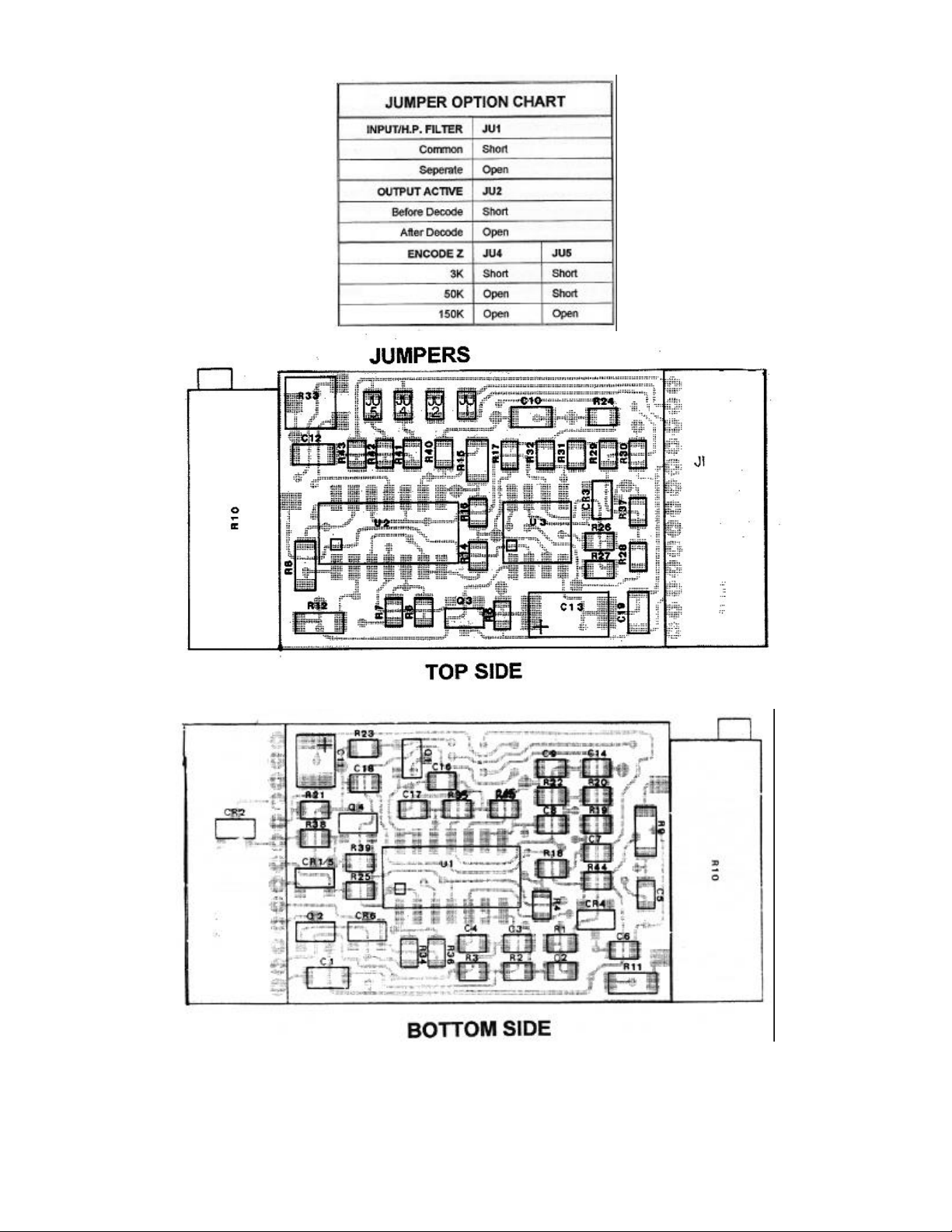
INSTALLATION
Mounting:
Use of a double-sided adhesive pad eliminates hardware
requirements. Mount the ST-146 on a clean, dry surface, oriented
to allow easy routing of the wiring to the radio. Press firmly after
mounting to ensure good adhesive contact. Do not touch the
adhesive or attempt to re-position the unit after mounting. The
ST-146 has been designed for maximum immunity to RF
interference; however, you should locate the unit as far as
possible from the radio's RF power stages. To further minimise
RF problems, twist the RED and BLACK leads together and
maintain all leads at minimum length.
Radio Interface:
The interface between the ST-146 board and the radio is by 13
wire leads on a miniature low profile connector. Most
applications will not require the use of all leads. Unused leads
should be removed from the connector by carefully lifting the
small tab near each connection pin and pulling the wire from the
connector. We recommend this method (rather than cutting
wires) because it allows reusing pins if an error is made.
[9] Negative (-) Supply (BLACK): Connect to System (-)
(Ground)
[3] Positive (+) Supply (RED):Connect to (+) Supply ( 5.5Vdc
to 16Vdc)
[13] Encode Output (WHT/GRN): Most F.M. two-way radios
make provisions for CTCSS modulation. This point is generally
after the speech modulation limiter, and near the voice deviation
control. The impedance at this point varies from radio to radio.
Three parallel resistors (1K, 51K, & 150K) are in series with the
ST-146 output circuit, and the 1K and 51K resistors may be
eliminated from the circuit by removal of JU4 and or JU5.
Remove JU4 orJU4 and JU5 to provide a correct tone level
without loading the radio modulator circuit and reducing voice
modulation. A CTCSS deviation level of ±750 Hz is
recommended.
[12] Tone Input (GREEN): Jumpered to Hi-Pass Filter input by
JU1. Connect directly to the FM receiver detector audio output.
Breaking the audio path at this point will allow insertion of the
Hi-Pass Filter. If it is not practical to break the audio path at this
point, refer to Hi-Pass Filter input (BLUE).
[11] Hi-Pass Filter input (BLUE): Use only when Tone input
(Green) cannot be used for Hi-Pass Finer input. Remove JU1 for
applications where breaking the audio path at the FM receiver
detector is not practical Hi-Pass Filter input audio should be
taken at the most convenient point
SELECTONE INC. •• 3501 BREAKWATER AVE •• HAYWARD, CA. 94545-3610
(510) 781-0376 •• NATIONWIDE TOLL FREE (800) 227-0376 •• FAX: (510) 781-5454 E-MAIL [email protected]
Operating Instructions
MODEL ST-146 Micro-Miniature
CTCSS Encoder/Decoder

[1] HiPass Filter Output (WHT/BLU): Connect to place the
Hi-Pass Filter in series with receiver audio path.
NOTE: The Hi-Pass Filter will not work in high level audio
stages such as speaker leads.
[4] Decode (-) (WHT/ORG): For applications where the radio
mute point must be held at Negative (-) Supply (Ground) during
mute Remove JU2 for applications requiring (-) Supply
(Ground) during decode.
[5] Decode (+) (BLK/ORG): For applications where the radio
mute point must be held Positive (+) during mute. Remove JU2
for applications requiring Positive (+) during decode.
[2] Hi-Pass Filter Mute (VIOLET): Connect to Decode (-)
(WHT/ORG) if none of the above mute conditions apply.
[1] Monitor (BROWN): PRIMARY CONTROL of
Encode/Decode functions. Connect to (-) Supply through
Monitor/hook switch to enable Decode and mute radio. Open
from (-) Supply to cause Encode and Monitor (Unmute radio).
_______
[8] Monitor (BLK/BRN): If your monitor switch closes to
Negative (-) Supply (Ground) to monitor, then MONITOR
(Brown) must be connected to Negative (-) Supply. Connect this
lead (BRN/BLK) to your Monitor hook switch.
____
[10] PTT (BLK/YEL): For applications with PTT closure to
Negative (-) Supply (Ground) during transmit Connect to PTT
in the radio. Required only if you must Encode without
Monitor.
[6] PTT (YELLOW): For applications where a keyed Positive
(+) is available during transmit. Required only if you must
Encode without Monitor.
OPERATING SPECIFICATIONS
Operating Voltage: 5.5Vdcto 16Vdc
Operating Current: Less than 5mAdc
Frequency Range: 67 to 250.3Hz, continuously tuneable
Temperature Range: 30°C to +60°C
Frequency Stability: Exceeds EIA RS-220A
(less than ±1.5%, typically less
than ±0.2%)
Encode Output Level: Adjustable 0 to greater than 1Vrms
with 8Vdc to 18Vdc supply
Encode Distortion: Less than 1%THD
Decoder Input Level: 10mVrms to 2Vrms (supply dependent)
Decoder lnput Z: Greater than 100K
Hi-Pass Filter: May be rnuted by decode
output
Decoder Activate: Field seledable (+) or (-) logic
Decoder Output: Open collector sink to (-) Supply or
source (+) voltage. Four possible out-
put conditions or Hi-Pass filter muting.
Interface: 18" flying leads terminated at
miniature
low profile connector.
Size: 1.68" L X 0.80" W X .25" H
4.27cm X 2.03cm X .64cm
***NOTICE***
If you are using a Selectone Application Note intended for the ST-104 please note
the following: If the YELLOW wire of the ST-104 is shown plugged into pin 3 of
the tone board use the BLACK/YELLOW wire on the ST-146 for this connection.
If the WHITE/ORANGE wire of the ST-104 is shown plugged into pin 5 use the
BLACK/ORANGE wire on the ST-146 for this connection. If the modification
instructions advise cutting R25 on the ST-104, ground the Brown wire on the ST-
146. R41 and R42 are equivalent to JU4 and JU5. All other application information
contained in Application Notes intended for the ST-104 is transferable to the ST-
146. ST-104 ST-146
---------------------------------------------------------------
YELLOW (pin 3) = BLACK/YELLOW
WHITE/ORANGE (pin 5) = BLACK/ORANGE
Cut R25 = Ground BROWN
R41 = JU4
R42 = JU5
REVIEW BY: DATE:
Engr: _____________________ Manual #: M501-2855
Revision: 960419-1
Mktg: _____________________ Last Edit
Date:4/18/96 Edited By: RTS
Prod: _____________________
3501 Breakwater Ave. Hayward, CA. 94545-3610
(510) 781-0376 (800) 227-0376
Fax: (510) 781-5454
E-MAIL [email protected]
WARRANTY POLICY
All standard Selectone products are guaranteed to meet or exceed published performance
specifications and are warranted against defects in material and workmanship for a period of five
years from the date of purchase. Special configurations and non-standard systems are warranted
for a period of one year.
If any standard Selectone product fails to operate within the first 90 days from the date of
purchase, Selectone will immediately send a replacement unit post-paid via airmail or UPS Blue
Label (air), and will issue full credit, including freight, upon the return of the defective unit(s).
For special warranty replacement service , call Selectone Customer Service Department TOLL
FREE at 1-800-227-0376. C.O.D. customers must return the defective equipment prior to
exchange or will receive the replacement C.O.D. with credit issued only on the return of the
defective equipment.
After 90 days, this warranty is specifically limited to correction of the defects by factory or
replacement of faulty equipment or parts.
All warranty repairs must be performed at the Selectone factory in Hayward, California. No credit
will be given for unauthorized repair work attempted by the customer. Any unauthorized
alterations or modification of the equipment , damage external source, or removal or alteration
the serial number label or date code, will void the warranty. Specifically exclude from this
warrant are batteries, LED’s, fuses, lamps, and damage caused by lightning, power surges, or
mechanical abuse.
Equipment for repair may be returned to the factory without prior written authorisation: however,
a note must be sent with the packing list briefly describing the nature of the defect.
Other Selectone Media Converter manuals


Popular Media Converter manuals by other brands


UW Technics
UW Technics 11080-HSS user manual

LumaSense technologies
LumaSense technologies Profibus Operation manual

Elipson
Elipson WiiM Mini user guide

Allied Telesis
Allied Telesis AT-GS2002 Series installation guide

Gopel Electronic
Gopel Electronic USB 4113 user manual

Polytron
Polytron OPM-LNB circ 032 manual