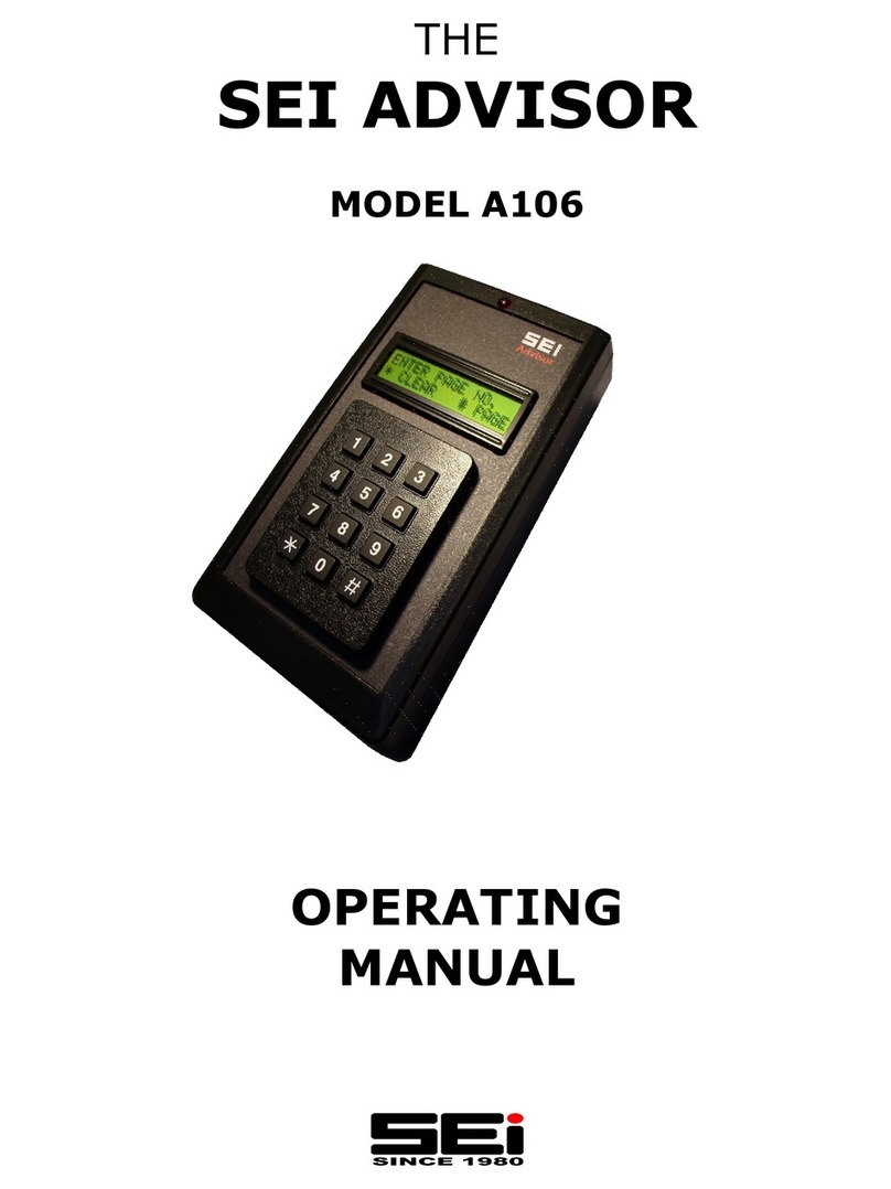
SEI ADVISOR AE100 User manual

ENCODER / DECODER / RECORDER
PROGRAMMING AND INSTALLATION
seinnovators.com
SEI ADVISOR WALL MOUNT
SEI ADVISOR DESKTOP
SEI RECORDER

PRODUCTS 4
PROGRAMMING MAIN MENU 5
PROGRAM ENCODER 6
PROGRAM DTMF 7
PROGRAM DECODER 8
PROGRAM STACKS 9
VIEW/DELETE SLOTS 10
DELAY ADD/DELETE 11
DE-EMPHASIS ADD/DELETE 11
SOFTWARE VERSION 12
CLEAR MEMORY 12
CONFIGURE RELAYS FOR WAKEUP SEQUENCE 12
SET WAKEUP SEQUENCE TIMEOUT 12
SETUP 13
PROGRAM ALERT RELAY 13
ADD ALIAS 14
EXIT PROGRAM 14
SCHEMATIC 15
BOARD LAYOUT 16
INSTALLATION 18
SETUP AND PROGRAMMING 22
SCHEMATIC 30
BOARD LAYOUT 31
INSTALLATION 33
ADVISOR ENCODER / DECODER
RECORDER

SYSTEM MODULE INTERCONNECTIONS
MIC AUDIO FOR RECORDER 35
ADVISOR ENCODER / DECODER WITH MIC 36
AUDIO FROM MIC INTERCONNECT ADAPTOR
ADVISOR ENCODER / DECODER CONNECTED 37
TO ACCESSORY JACK
RECORDER CONNECTED TO ACCESSORY JACK 37
ADVISOR ENCODER / DECODER WITH RECORDER 38
CONNECTED TO ACCESSORY JACK
ADVISOR ENCODER / DECODER WITH RECEIVER 38
ALLOWS BASE STATION TO SCAN
ADVISOR ENCODER / DECODER WITH RECEIVER 39
AND RECORDER ALLOWS BASE STATION TO SCAN
RECORDER MOBILE INSTALLATION 39
ADVISOR WALL MOUNT RECEIVE ONLY 40
WITH RECORDER
ADVISOR WALL MOUNT ENCODER / DECODER 41
WITH RECORDER
ADVISOR WALL MOUNT ENCODER / DECODER 42
WITH RECEIVER ALLOWS BASE STATION TO SCAN
ADVISOR WALL MOUNT ENCODER / DECODER 42
WITH RECORDER AND RECEIVER ALLOWS
BASE STATION TO SCAN
ADVISOR DESKTOP EXTRA ENCODER / DECODER 43
WITH RECORDER
ADVISOR DESKTOP EXTRA ENCODER / DECODER 43
WITH RECEIVER ALLOWS BASE STATION TO SCAN
ADVISOR DESKTOP EXTRA ENCODER / DECODER 44
WITH RECORDER AND RECEIVER ALLOWS
BASE STATION TO SCAN
RECORDER WITH MIC AUDIO FROM MIC 44
INTERCONNECT ADAPTOR
RECEIVER SCHEMATIC 45
WARRANTY 46

*
*If the Recorder is slaved to the Advisor the Recorder will only record after the Advisor is tripped.
It is reset with the “*” on the Advisor key pad.
SEI
Advisor
Desktop
Extra
SEI Recorder
Station/Mobile
WIFI Connectivity
CLOUD Connectivity
SEI
Advisor
Wall Mount
SEI Receiver
SEI
Advisor
Desktop
ENCODING / DECODING / RECORDING
FOR PUBLIC SAFETY
TABLE OF CONTENTS

Hold for
6 Sec. PROGRAM
ENCODER
PAGE 6
PROGRAM
DTMF
PAGE 7
PROGRAM
STACKS
PAGE 9
PROGRAM
DECODER
PAGE 8
DELAY
ADD/DEL
PAGE 11
VIEW/DEL
SLOTS
PAGE 10
CLEAR
MEMORY
PAGE 12
EXIT
PROGRAM
MODE
Programming is intuitive. Just follow
the Screens.
Hold the “#” key for 6 seconds to En-
ter the Program Mode.
Use the “#” key to step through the
main options.
Use the “*” key to select the option.
“*” press WITH NO ENTRY, will return
to main Program Mode menu
To exit the Program Mode at any time
just hold the “#” key for 6 seconds.
Normal Screen
Displayed for 1.5 Sec.
SETUP
PAGE 13
DE-EMPHASIS
ADD/DEL
PAGE 11
PROGRAM
ALERT RELAY
PAGE 13
TABLE OF CONTENTS
CONFIGURE
RELAYS
PAGE 12
NEW WUS
TIMEOUT
PAGE 12

ALERT TONE
ADDED
Displayed for 1.5 Seconds
ADD ALIAS
PAGE 14
Select Program Encoder from the Pro-
gram Mode by pressing “*”.
Enter the Slot number you want to Pro-
gram.
Slots 0—999.
Enter the First Tone in the Two Tone Se-
quence. Include the Digit after the Deci-
mal Point. (For 853.4 Enter 8534)
Enter the Second Tone in the Two Tone
Sequence. Include the Digit after the
Decimal Point.
(For 1764.5 Enter 17645)
Select “Alert Tone” for an Alert Tone to
follow the Page.
The Slot Number will be Displayed for
1.5 Sec.
Tone A and Tone B will be Displayed.
Press “#” to Program the Slot.
(“*” TO Start Again)
Press “*” to enter a
16 character Alias for the Slot.
(See Instructions on Page 25)
For Group Call make the A Tone and the
B Tone the Same.
It will now Return to “Program Encoder”
to Program another Slot if Needed.
For 853.4
Enter 8534
For 1764.5
Enter 17645
Example
1764.5
Example
853.4
Example
452
TABLE OF CONTENTS

Select Program DTMF from the Program
Mode by pressing “*”.
Enter the Slot number you want to Pro-
gram.
Enter the number of DTMF Tones You
want to Send. (Min 1, Max 8)
Enter “1” for Standard DTMF, Enter “2”
for Knox F1 DTMF.
Enter the DTMF Digits One at a Time.
0 = 0 1 = 1 2 = 2 3 = 3 4 = 4
5 = 5 6 = 6 7 = 7 8 = 8 9 = 9
10 = * 11 = # 12 = A 13 = B 14 = C
15 = D
The Tones are then Displayed with the
Type. Press “#” to Program the Slot.
Press “*” to enter a 16 character Alias for
the Slot. (See Instructions on Page 25)
It will now Return to “Program DTMF” to
Program another Slot if Needed.
Displayed for 1.5 Seconds
Enter 1 - 8 (Example 5)
Enter 1 or 2 (Example 1)
Enter Digits One at a Time
(Example 3, 5, 9, 2, 8)
All Digits
Are Entered
ADD ALIAS
PAGE 14
ENTER THE SLOT NO.
THAT HOLDS THE
DTMF SEQUENCE
Example
238
PRESS # TO
ACCEPT THE
ENTRY
TABLE OF CONTENTS

Displayed for 1.5 Sec.
Select Program Decoder from
the Program Mode by press-
ing “*”.
Enter the Slot number you
want to Program.
Slots 1—100.
Enter the First Tone in the
Two Tone Sequence. Include
the Digit after the Decimal
Point. (For 853.4 Enter 8534)
Enter the Second Tone in the
Two Tone Sequence. Include
the Digit after the Decimal
Point. (For 1764.5 Enter
17645)
The Slot number will be Dis-
played for 1.5 seconds.
Tone A and Tone B will be Dis-
played. Press “#” to Program
the Slot.
Add WAKE-UP Sequence Op-
tion and select 1, 2 or 3.
Deactivate Relay Option
(Not Available if WAKE-UP Se-
quence or Add Re-Page are
Selected)
It will now Return to
“Program Encoder” to
Program another Slot if Need-
ed.
Enter 1, 2 or 3
Example
52
Example
853.4
Example
1764.5
For 853.4
Enter 8534
For 1764.5
Enter 17645
PRESS # TO
ACCEPT THE
ENTRY
TABLE OF CONTENTS

ADD ALIAS
PAGE 14
Displayed for 1.5 Sec.
Example
Slot 98
Step Through
all of the
Slots in the
Stack
Displays when End
of Stack is Reached
The Advisor will Accept up to 50
Stacks with up to 48 Slots in each
Stack.
Programming is Intuitive. Just fol-
low the Screens.
Enter the Slot number that will Hold
the Stack (Example 98)
Press # to Accept the Slot number
Enter the Slot number for Each Slot
in the Stack. (Maximum of 48 Slots)
Press “*” to enter a 16 character
Alias for the Slot. (See Instructions
on Page 25)
Press “#” to Review the Slots en-
tered into the Stack or Press “*” to
Finish.
Display the Slot number that Holds
the Stack.
Keep Pressing “#” to Step Through
each Slot in the Stack.
When the End of the Stack is
Reached you can choose to keep the
Stack or Delete it.
ENTER UP TO
48 SLOTS
NUMBERS
THIS IS THE SLOT THAT
WILL BE ENTERED TO
PAGE THE STACK
Displayed for
1.5 Sec.
TABLE OF CONTENTS

CODES: Tell What Decode Functions
are Programmed in the Slot
Enter a Slot
Number
Example 52
Displayed for 1.5 Seconds
NO
NO
ENTER
Enter a Slot
Number
Example 452
Displayed for 1.5 Seconds
If Slot is Two Tone If Slot is DTMF If Slot is a Stack
Displayed for 1.5 Seconds Displayed for 1.5 Seconds
Display Alias
Display DTMF
Digits
Display Alias
Step Through
all of the
Slots in the
Stack
YES
Return to
Program
Mode
Displayed for 1.5 Seconds
ENTER
KEEP
KEEP
KEEP
CODES
0 ALERT RELAY ONLY
2015 DEACTIVATE ALERT RELAY
20000 WAKE UP SEQUENCE 1
30000 WAKE UP SEQUENCE 2
40000 WAKE UP SEQUENCE 3
ALERT RELAY IS ACTIVE WITH WAKE UP SEQUENCE
KEEP
KEEP
YES
YES
Select from
Program Menu
TABLE OF CONTENTS

If a Radio has a PTT ID when it is Keyed then a Delay must be add-
ed so the Tones will Transmit After the ID is Done.
Displayed for 1.5 Seconds
Displayed for 1.5 SecondsDisplayed for 1.5 Seconds
Return to Program Mode
Menu at “DE-EMPH ADD/DEL
If Transmit Audio has Pre–emphasis (Such as Mic Audio) Add De-emphasis
to compensate so the Encoder Audio is Flat
Displayed for 1.5 Seconds
Return to Program Mode
Menu at “Software Ver.”
Displayed for 1.5 SecondsDisplayed for 1.5 Seconds
TABLE OF CONTENTS

Clear the Encoder Memory, Clear the Decoder
Memory or Clear the Stack Memory.
Return to Program
Mode Menu at
“SETUP”
Displayed for 1.5 Seconds
NO
YES
Displayed While Clearing
Displayed for 1.5 Seconds
YES
Displayed While Clearing
NO
YES
YES
YES
YES
NO
NO
YES
Displayed While Clearing
NO NO
Displayed for 1.5 Seconds
Readout the Software Version Installed.
Return to Program Mode
Menu at “CLR MEMORY?”
TABLE OF CONTENTS
DEFAULT IS RED LIGHTS RELAY ON FOR 4 SECS
THEN THE ROOM LIGHTS RELAY ON. COMBINING
THEM TURNS THEM BOTH ON AT THE SAME TIME.
ALTER THE LENGTH OF THE WAKEUP SEQUENCE
RELAYS ON TIME FROM 1 TO 25 MINS.

PRESS “1” TO GENERATE TEST WAKE-UP SEQUENCE 1
PRESS “2” TO GENERATE TEST WAKE-UP SEQUENCE 2
PRESS “3” TO GENERATE TEST WAKE-UP SEQUENCE 3
(The WAKE-UP Sequence Test Also Sends Radio Audio to the PA System and Activates
the Relays for the Red Lights and the Room Lights.)
PRESS “4” TO RESET RELAYS
PRESS “5” TO KEY THE RADIO AND GENERATE 8 SECONDS OF 350 HZ
PRESS “6” TO KEY THE RADIO AND GENERATE 8 SECONDS OF 1000 HZ
PRESS “7” TO KEY THE RADIO AND GENERATE 8 SECONDS OF 2700 HZ
PRESS “8” TO SEND RECEIVER AUDIO TO THE SPEAKERS
EXIT
YES
Setup is used to Generate Tones and Set Relays so
Levels can be Adjusted During Installation.
Displayed for 1.5 Sec.
The Default Operation of the Alert Relay
is a 200 ms closure of the Contacts when
the Advisor is Alerted.
This can be changed in the Programming
so when the Advisor is Alerted the Alert
Relay will remain on until the “*” Button
is pressed to Reset it.
TABLE OF CONTENTS

Continue in
Program Mode
Return to Normal
Operation
Holding # in for 6 Seconds
will Exit Program Mode
from any Program Menu
Location
ASCII CODES
Enter the ASCII Character
for up to 16 Entrees
Press # with No Entry To Finish
Add up to 16 ASCII Characters to an
Encoder Slot.
Characters are Entered One At a Time.
When Finished the # is Pressed with
No Entry.
Return to the Program Menu
that it Came From
(Encoder, DTMF or Stacks)
32 SPACE
33 !
34 "
35 #
36 $
37 %
38 &
39 '
40 (
41 )
42 *
43 +
44 ,
45 -
46 .
47 /
48 0
49 1
50 2
51 3
52 4
53 5
54 6
55 7
56 8
57 9
58 :
59 ;
60 <
61 =
62 >
63 ?
Example:
To Enter EAST GORHAM FIRE
Enter 69, 65, 83, 84, 32, 71, 79, 82, 72, 65, 77, 32, 70, 73, 82, 69
E A S T G O R H A M F I R E
64 @
65 A
66 B
67 C
68 D
69 E
70 F
71 G
72 H
73 I
74 J
75 K
76 L
77 M
78 N
79 O
80 P
81 Q
82 R
83 S
84 T
85 U
86 V
87 W
88 X
89 Y
90 Z
91 [
92 \
93 ]
94 ^
95 _
TABLE OF CONTENTS

RADIO CABLE
J2 RJ45 CABLE CONNECTION TO RADIO
1 PTT BRN RELAY CONTACT TO GND
2 TX AUDIO OUT BLU SEE NOTE
3 RX AUDIO IN YEL SQUELCHED AUDIO
4 TX AUDIO IN GRN MIC AUDIO
5 POWER RED 12 - 15VDC
6 GROUND BLK GROUND
7 ALERT RELAY ORG CLOSURE WITH DECODE
8 ALERT RELAY WHT CLOSURE WITH DECODE
NOTE: TX AUDIO OUT IS BEST CONNECTED TO A FLAT AUDIO INPUT. IF THE INPUT
HAS PRE-EMPHASIS (SUCH AS A MIC INPUT) THEN SELECT DE-EMPHASIS IN THE PRO-
GRAM MODE.
THE RX AUDIO IN SHOULD BE CONNECTED TO SQUELCHED AUDIO THAT DOES NOT
VERY WITH THE VOLUME CONTROL.
THE SEI RECEIVER CONNECTS TO RX AUDIO IN AUTOMATICALLY WHEN PLUGGED IN
SERIES WITH THE ADVISOR. (SEE PAGE 18)
GROUND RX AUDIO IN IF NOT USING DECODER.
TX AUDIO IN IF NO GOOD CONNECTION FOR TX AUDIO OUT IS AVAILABLE THEN
YOU CAN CUT INTO THE MIC LINE AND CONNECT TX AUDIO IN AND TX AUDIO OUT
IN SERIES. (SEE SCHEMATIC PAGE 31)
TABLE OF CONTENTS

PA/LIGHTS
J3 RJ45 CAT 5
1 ROOM LIGHT RELAY BROWN
2 ROOM LIGHT RELAY WHITE/BROWN NORMALLY OPEN
3 RED LIGHT RELAY GREEN
4 RED LIGHT RELAY WHITE/GREEN NORMALLY OPEN
5 ALERT RELAY ORANGE
6 ALERT RELAY WHITE/ORANGE NORMALLY OPEN
7 AUDIO TO PA AMP BLUE
8 AUDIO TO PA AMP WHITE/BLUE BALANCED AUDIO
SHIELDED CAT 5 CAN BE USED IN HIGH RF ENVIRONMENTS.
Cat 5 Cable is run to the Equipment Room to connect to the PA Amplifier.
The Lights can be Controlled Remotely through the Building Wiring using
PULSE WORX Wall Switch Receivers, Receiver Modules and Transmitter Modules.
Transmitter Unit Uses
the Relay Contacts from
the Advisor to Activate/
Deactivate the Wall
Switches or the Plug-in
Modules
Wall Switch gets a Signal
from the Transmitter Unit
to Turn On or Off
Plug-in Module gets a
Signal from the Transmitter
Unit to Turn On or Off
TABLE OF CONTENTS

ADJUST ENCODER
NOTE: TX AUDIO OUT IS BEST CONNECTED TO A FLAT AUDIO INPUT. IF THE INPUT
HAS PRE-EMPHASIS (MIC INPUT) THEN SELECT DE-EMPHASIS IN THE PROGRAMMING
MENU.
SELECT “SETUP” IN THE PROGRAM MODE. USE “4”, “5”, AND “6” TO KEY THE RADIO
AND GENERATE 350 HZ, 1000 HZ, AND 2700 HZ FOR 8 SEC.
ADJUST TX AUDIO OUT (MULTI TURN POT) FOR PROPER DEVIATION WITH ALL 3
TONES. SELECT DE-EMPHASIS IF NEEDED.
ADJUST DECODER
BECAUSE OF THE IMPORTANCE OF RELIABLY WAKING THE STATION PERSONAL,
THE SIGNAL FROM DISPATCH SHOULD BE FULL QUIETING OR NEAR FULL QUIET-
ING. (–90 DBM OR BETTER)
THE RX AUDIO IN SHOULD BE CONNECTED TO SQUELCHED AUDIO THAT DOES NOT
VERY WITH THE VOLUME CONTROL.
GROUND RX AUDIO IN IF NOT USING THE DECODER FUNCTION OF THE ADVISOR.
1 _ FEED A 2850HZ TONE INTO THE RECEIVER AT –94DBM
2 _ ADJUST “RX AUDIO IN” CLOCKWISE UNTIL THE DISPLAY JUST STARTS TO FLASH
“RECEIVING AUDIO” ADJUST BACK AND FORTH TO BE SURE IT IS JUST ON THE
EDGE OF STARTING TO FLASH “RECEIVING AUDIO”
3 _ TURN “RX AUDIO IN” CLOCKWISE 1 FULL TURN PAST THIS POINT
ADJUST THE LEVEL OF THE WAKE-UP TONES AND RADIO AUDIO TO
THE PA SYSTEM
GENERATE A 1000HZ TONE INTO THE RADIO AT 1.5 KHZ DEVIATION. THEN ADJUST RA-
DIO TO PA FOR A GOOD LEVEL OF THE 1000HZ TONE TO THE PA SYSTEM.
Go to Program - Setup. PRESS 1, 2 OR 3 TO GENERATE A WAKE-UP SEQUENCE. ADJUST
WAKE-UP TONES TO PA FOR A GOOD LEVEL.
PRESS 4 TO RESET THE RELAYS WHEN DONE.
TABLE OF CONTENTS
This manual suits for next models
10
Table of contents
Other SEI Media Converter manuals
Popular Media Converter manuals by other brands

Contec
Contec CPS-PWD-30AW24-01 user guide

Tripp Lite
Tripp Lite P136-06N-HV-V2 quick start guide

Black Box
Black Box Video to VGA Converter Specifications

Black Box
Black Box MicroConverter G.703 manual

PULSEEIGHT
PULSEEIGHT DOLBY DAC Quick reference guide

COLORKINETICS
COLORKINETICS Multi-Protocol Converter 8 installation instructions