Greentek LCH-4H User manual

Light commercial models
Heat Recovery Ventilators
Installation, Operations, and Maintenance Manual
Manuel d’installation, de fonctionnement et de maintenance
LCH-4H • LCH-7H • LCH-12H
Your ventilation system should be installed in conformance with the appropriate provincial requirements or, in the absence of
such requirements, with the current edition of the National Building Code, and / or ASHRAE’s “Good Engineering Practices”.
Greentek reserves the right to modify, at any time and without notice, any or all of its products’ features,
designs, components and specifications to maintain their technological leadership position.
Please visit our website www.greentek.ca for more detailed technical information.
United States
10048 Industrial Blvd., Lenexa, KS, 66215
Tel.: 800.747.1762 • Fax: 800.487.9915
Canada
50 Kanalflakt Way, Bouctouche, NB, E4S 3M5
Tel.: 800.565.3548 • Fax: 877.747.8116
Item #: 464080
Rev Date: 2023-05-26
No. d'article: 464080
Date de révision: 2023-05-26
Votre système de ventilation doit être installé conformément aux exigences de la province où vous habitez ou, à défaut de
telles exigences, conformément à l’édition actuelle du Code national du bâtiment du Canada ou aux « méthodes d’ingénierie
appropriées » de l’ASHRAE.
Greentek se réserve le droit de modifier partiellement ou entièrement, en tout moment et sans préavis, les
caractéristiques, la conception, les composants et les spécifications de ses produits, afin de conserver sa
position de leader de technologie.
S'il vous plaît visitez notre site siteweb www.greentek.ca pour des informations techniques plus détaillées.

2
Note Warning/
Important
note
Information Technical
information Practical tip
PLEASE READ AND SAVE THESE INSTRUCTIONS
Before installation, careful consideration must be given to how this system will operate if connected to any other
piece of mechanical equipment, i.e. a forced air furnace or air handler, operating at a higher static pressure. After
installation, the compatibility of the two pieces of equipment must be confirmed by measuring the airflows of the
Heat / Energy Recovery Ventilator. It is always important to assess how the operation of any HRV/ERV may inter-
act with vented combustion equipment (i.e. Gas Furnaces, Oil Furnaces, Wood Stoves, etc.).
Never install a ventilator in a situation where its normal operation, lack of operation or partial failure may result
in the backdrafting or improper functioning of vented combustion equipment!!!
Products are designed and manufactured to provide reliable performance, but they are not guaranteed to be 100%
free of defects. Even reliable products will experience occasional failures, and this possibility should be recognized
by the user. If these products are used in a life support ventilation system where failure could result in loss or injury,
the user should provide adequate back-up ventilation, supplementary natural ventilation or failure alarm system, or
acknowledge willingness to accept the risk of such loss or injury.
Your ventilation system should be installed in accordance with the local building code that is in effect. In absence
of such requirements, it is recommenced to check with local authorities having jurisdiction in your area prior to
installing this product.

3
Table of content
INSTALLATION
Location ...........................................................................4
Port Configuration .....................................................................4
Installing Drain Line ....................................................................5
Installing Duct Connections...............................................................6
AIRFLOW BALANCING.........................................................................7
INSTALLATION EXAMPLES
Fully Dedicated Systems.................................................................8
Partially Dedicated Systems (direct connections) ...............................................8
Partially Dedicated Systems (indirect connections) ..............................................9
Simplified Installation ...................................................................9
MODES OF OPERATION .......................................................................10
Speed Setting .......................................................................11
WALL CONTROLS ...........................................................................12
MAINTENANCE .............................................................................14
WIRING DIAGRAM ..........................................................................15
INSTALLATION VERIFICATION TEST .................................................................. 21
WARRANTY . . . . . . . . . . . . . . . . . . . . . . . . . . . . . . . . . . . . . . . . . . . . . . . . . . . . . . . . . . . . . . . . . . . . . . . . . . . . . . . 21
PARTS LIST ...............................................................................43
Greentek Product Numbers Explained
LCH-4H
L = Lighting
C = Commercial
H = Horizontal Configuration
4 = 450 CFM
H = Heat Recovery (HRV)
Greentek Product Numbers Explained
LCH-7H
L = Lighting
C = Commercial
H = Horizontal Configuration
7 = 750 CFM
H = Heat Recovery (HRV)
Greentek Product Numbers Explained
LCH-12H
L = Lighting
C = Commercial
H = Horizontal Configuration
12 = 1200 CFM
H = Heat Recovery (HRV)

4
Installation
Location
The HRV must be located in a heated space where it will be possible to conveniently service the unit. Typically the HRV would be located in the
mechanical room, above a drop ceiling or an area close to the outside wall where the weatherhoods will be mounted. Attic installations are not normally
recommended due to extreme temperatures, and difficulty in performing required service & maintenance. If an attic is selected, special care should be
taken in ensuring the unit will perform as intended. Unit may need to be protected with insulated shelter, built on site.
Connecting appliances to the HRV It is not recommended, including:
• clothes dryer
• kitchen exhaust hoods
• combustion venting
• central vacuum system
These appliances may cause lint, dust or grease to collect in the HRV , damaging the unit.
Connecting any of these type of appliances to the HRV will invalidate your warranty
A
B
C
DE
F
G
Model A B C D E F G
Kg lbs Kg lbs in. mm. Kg lbs Kg lbs Kg lbs in. mm.
LCH-4H 16.6 36.6 15.6 34.4 12.6 320 58 127.9 13.6 30 12.7 28 17.63 448
LCH-7H 23.8 52.5 22.5 49.6 15.4 390 85 187 20 44 18.8 41.3 17.6 448
LCH-12H 30.4 67 27 60 21.4 544 109 241 27.7 61 24.3 53.5 18 455

5
Installing Drain Line
Through normal operation and including defrost mode, the HRV may produce some condensation. This water should flow into a nearby drain, or be taken
away by a condensate pump. The HRV and all condensate lines must be installed in a space where the temperature is maintained above the freezing
point. A “P” trap should be made in the drain line. This will prevent odors from being drawn back up into the unit.
Install the drain hose, making a “P” trap
Port configuration
The unit has access doors on the front and back. Also, the main control panel may be moved from front to back allowing for ducting layout.
LCH-4H, LCH-7H, LCH-12H
COLD SIDE
COLD SIDE
WARM SIDE
WARM SIDE
Factory Setting. Unit may be easily reversed
in eld.

6
Installing ducts going to / from outside
Installing the ducting to the weatherhoods
Outside weatherhoods
The weatherhoods must have built-in "bird" screens with 1/4 inch (6.35 mm) minimum mesh to prevent birds and rodents from entering into the
ductwork. Do not use smaller mesh as it will be very susceptible to plugging up. The preferred location of the weatherhoods is:
• No less than 10 ft. (3 m) apart from each other.
• At least 18 inches (457.2 mm) above snow line or ground level.
• Supply hood must be kept away from sources of contaminants, such as automobile exhaust fumes, gas meters, garbage cans, containers,
cooling towers, tar roofs, etc.
• Avoid prevailing winds, whenever reasonably possible.
The outside perimeter of the weatherhood must be sealed to prevent leakage into the building.
The design and size of the weatherhoods or louvers chosen by the installer must allow for adequate free area. Water and snow penetration of the system
is minimized when the airflow does not exceed 1000 FPM (5.08 m/s) free area velocity.
Ducting from the weatherhoods–To and From the hrv
Galvanized sheet metal ducting with sufficient cross section with an integral single piece of insulated wrap with vapor barrier should be used to connect
the HRV to the weatherhoods. The R-value of the insulation should be adequate for condensation control. Insulated flex duct may be used in moderation,
if sized and installed properly. (Consult local codes)
All ducts should be sealed using a good bead of high quality caulking (preferably acoustical sealant) and a high quality aluminum foil tape, or other
approved duct sealant.

7
Exhaust air ducting
The stale air exhaust system is used to draw air from the points in the building where the worst air quality problems occur. ( See installation
examples in the manual.)
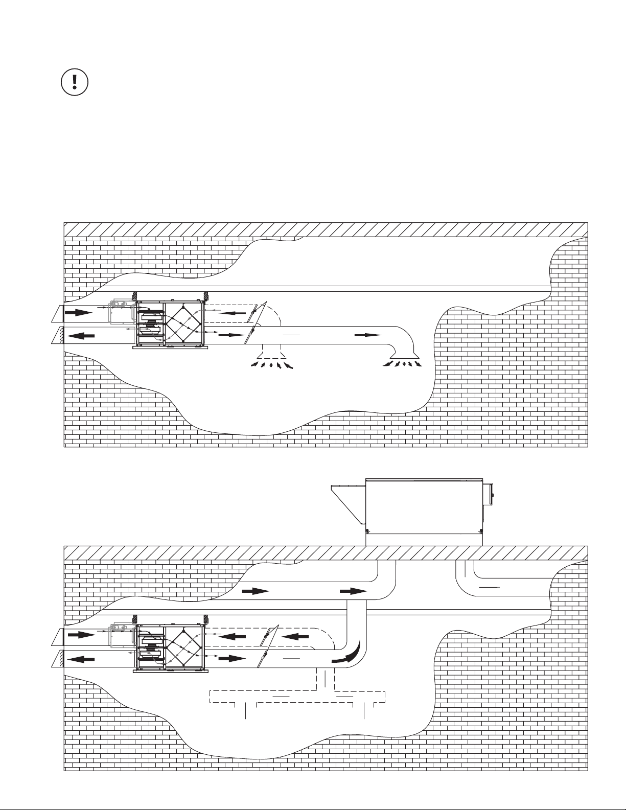
Installing ducts to / from inside
Direct connection to furnace/ air handler return duct
• Should you wish to hard duct the supply air directly into the cold air return of the HVAC systems, remember to check the airflow balance of the HRV
with the HVAC systems fan both “on”and “off” to determine that it does not imbalance the HRV more than 10%. Make sure you respect the minimum
distance from the supply air in of the HRV and the HVAC systems.
• It may be necessary to install a separate fresh air supply ductwork system if the heating is other than forced air.
When installing an HRV, the designer and installer should be aware of local codes that may require smoke detectors and/or firestats in the HVAC
or HRV ductwork.
Because an HRV is designed to bring fresh air into the building, structures may require supply voltage interrupt when smoke or flame sensors are
triggered, or when a central fire alarm system is activated.
To maximize airflow in the ductwork system, all ducts should be kept short and have as few bends or elbows as possible. Forty-five degree are
preferred to 90elbows. Use “Y” tees instead of 90elbows whenever possible.
All duct joints must be fastened with screws or duct sealant and wrapped with a quality duct tape to prevent leakage. Aluminum foil duct tape is
recommended.
Supply air ducting
In buildings without a forced air HVAC systems, fresh air should be supplied to all habitable areas. It should be supplied from high wall or ceiling
locations. Grilles that diffuse the air comfortably such as grille {MGE (metal) }grilles with "coanda effect" are recommended.
Optional inline duct heaters may be used to add heat if required.
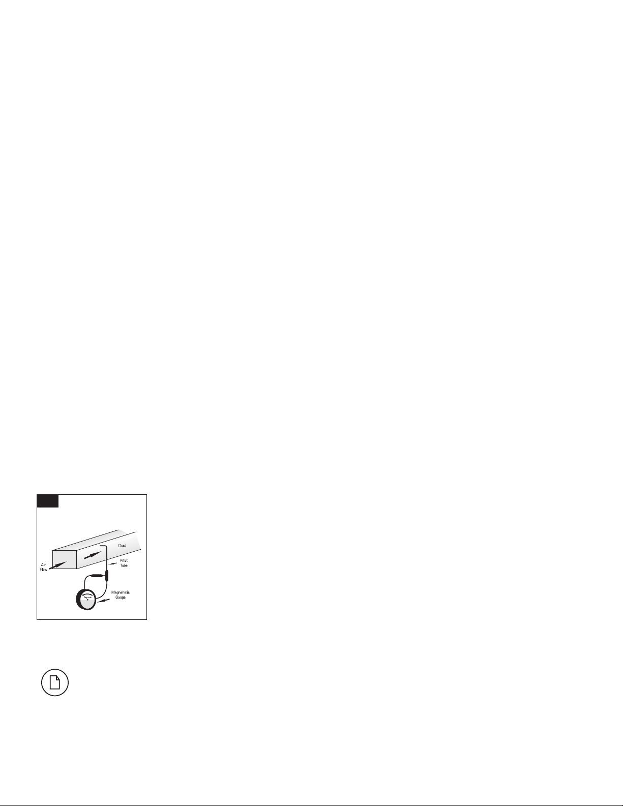
AThe duct’s airflow velocity
is generally measured
with a magnehelic gauge
and a pitot tube.
• To avoid airflow turbulence
and incorrect readings, the
airflow velocity should be
measured on steel ducting
a minimum of 3 duct
cross-sections from the
unit or elbow and before
any transition.
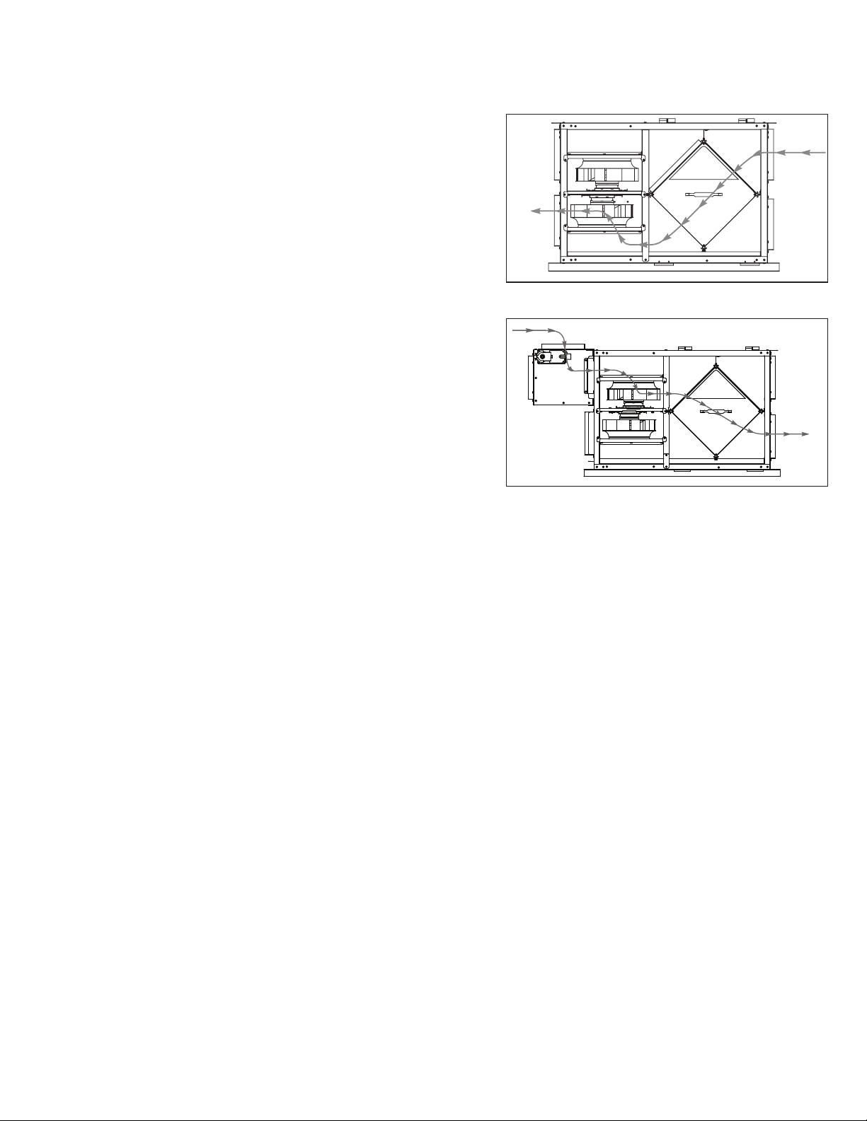
• The balancing procedure consists of measuring the exhaust air leaving the system and the supply air entering the system and ensuring that these
two are equal. A deviation of 10% or less is acceptable.
Airflow balancing
A*
Pitot tube and gauge
A professional air balancer should be contacted to commission the system properly. A skilled HVAC Tech may complete the balance
of air providing they possess the proper equipment. Call Greentek Technical support for assistance.

8
Installation examples
* Drawings are illustrations only and actual port locations and airflow directions may vary, consult unit spec sheets.
It is the responsibility of the installer to ensure all ductwork is sized and installed as designed to ensure the system will perform as intended.
The amount of air (CFM) that an HRV will deliver is directly related to the total external static pressure (E.S.P.) of the system. Static pressure
is a measure of resistance imposed on the blower by length of duct work/number of fittings used in duct work, duct heater etc.
Fully Dedicated System
• Stale air drawn from areas of contamination
• Fresh air supplied to main areas
• HRV airflow should be balanced
• External heating or cooling coil may be needed if air is not able to mix comfortably.
SUPPLY IN
EXHAUST OUT
HRV UNIT
SUPPLY DUCT
RETURN AIR DUCT
EXHAUST AIR TO HRV UNIT
AIR HANDLER UNIT
SUPPLY IN
BALANCING DAMPERS
OUTDOOR AIR
EXHAUST AIR
HRV UNIT
SUPPLY AIR
RETURN AIR SUPPLY AIR
BALANCING DAMPERS - LCH-12H ONLY
Partially Dedicated System (Direct Connection)
• Stale air drawn from areas of contamination
• Fresh air supplied to return of air handler
• Air Handler blower may need to operate when call for ventilation
• HRV airflow should be balanced

9
Installation examples (Cont'd)
* Drawings are illustrations only and actual port locations and airflow directions may vary, consult unit spec sheets.
It is the responsibility of the installer to ensure all ductwork is sized and installed as designed to ensure the system will perform as intended.
The amount of air (CFM) that an HRV will deliver is directly related to the total external static pressure (E.S.P.) of the system. Static pressure
is a measure of resistance imposed on the blower by length of duct work/number of fittings used in duct work, duct heater etc.
SUPPLY IN
EXHAUST OUT
HRV UNIT
RETURN AIR DUCT
AIR HANDLER UNIT
SUPPLY IN
BALANCING DAMPERS
SUPPLY IN
EXHAUST OUT
HRV UNIT
SUPPLY DUCT
EXHAUST AIR TO HRV UNIT
12" BREATHER SPACE
CEILING RETURN AIR PLENUM
AIR HANDLER UNIT
SUPPLY IN
BALANCING DAMPERS
Simplified Installation
• Stale air drawn from return of air handler
• Fresh air supplied to return of air handler, further down
stream of HRV exhaust
• Air Handler blower must operate when HRV is providing
ventilation
• HRV airflow should be balanced
Partially Dedicated System (Indirect Connections)
• Stale air drawn from areas of contamination
• Fresh air supplied into ceiling return air plenum or grille
• HRV airflow should be balanced

10
1. Continuous / Ventilation Mode
In this mode of operation both fans are operating and exchanging air with the outside. The
heat recovery ventilator (HRV) constantly exchanges the air at the rate you select, either
at low or medium speed, and switches to high speed when activated by an optional remote
control. The "Low (reduced)" and "High (Normal)" fan speed selection will cause the unit
to operate in continuous exchange mode at a reduced exchange rate. Continuous mode
is recommended, since pollutants are slowly but constantly being generated in a building.
2. Intermittent / Standby Mode
The system is always on standby and operates at high speed when activated by an
optional remote control (required): "Standby" should be selected if the user wishes to
stop the unit from continuous exchange.
3a. Defrost by evacuation
A preset defrost sequence is activated at an outdoor air temperature of 23ºF (-5ºC) and
lower.
During the defrost sequence, the supply blower shuts down & the exhaust blower continues
to ventilate for a preset time. The unit then returns to normal operation, and continues the
cycle.
3b. Defrost by recirculation (only available with GTDMK module)
A preset defrost sequence is activated at an outdoor air temperature of 23ºF (-5ºC)
and lower.
During the defrost sequence, the motorized damper in the bypass module (GTDMK)
temporarily blocks the incoming fresh air stream so that the warm air from the room can
circulate through the HRV. The exhaust blower shuts down and the supply blower
switches into high speed to maximize the effectiveness of the defrost strategy. During
this cycle, the unit will not create a negative pressure. Please note that these systems
are configured to defrost with the GTDMK devices installed on the fresh air from outside
port. Alternate configuration are available by contacting our technical support department.
Modes of operation
Stale Air
to Outside
Stale Air
from Inside
Recirculate Air from Inside
Supply air
to building

11
The ERV is shipped from the factory on low speed, intermittent operation can be obtained by toggling switch located on outside of cabinet.
The voltage selection for low (reduced) speed of the unit is done via jumpers shown in the illustration below. The default setting 75V.
Setting low speed
Low: 75V
(Factory Default)
Low: 90V
Configurable speed control for low (reduced) speed
CAUTION MAKE SURE THE POWER TO THE UNIT IS DISCONNECTED BEFORE MAKING ANY CHANGES

12
WALL CONTROLS
1. Ensure that unit is not plugged when connecting the control
2. Recirculation mode is only available in the Solace series and the C3.14 model.
The wiring connectors can be removed for easier connection.
* Please see instruction manuals for individual controls for proper wiring and set up of control systems.
CENTRAL CONTROLS
These cannot be used with another central control
*Maintain polarity between control and ERV
(+ →+ ; - →-)
FEATURES CONNECT TO
STS 2.0 • Our most complete, yet easy-to-use control system
• Sleek design with backlight touchscreen LCD
• ECO mode selects the best operating mode and speed for the season, minimizing energy use associated with
ventilation
• Set preferred indoor relative humidity range and ventilation mode for day and night conditions
• No battery to replace, all programmed settings are retained during power outages
• Maintenance reminder indicator
• Error code messages reduce troubleshooting time
EHC 2.5 • Three (3) modes of operation: Ventilation Mode, Recirculation Mode, Stand by Mode.
• Once you’ve selected the operation mode, the fan speed can be selected: Reduced, Medium,
Normal or 20min/h using the arrow buttons.
• Ventilation Mode: The ventilation system takes stale air from inside your home and replaces it
with fresh outdoor air while recovering the energy of the air that’s exhausted to the outside.
• Recirculation Mode: Your ventilation system takes air from areas of your home and
redistributes it in other rooms to avoid stagnant air areas and to distributes heated or cooled
air. No outdoor air is introduced to the building.
• Standby Mode: The ventilation system is inactive unless the indoor relative humidity is above
the setpoint on the control or a timer switch (installed separately) is activated.
EHC 2.0 • An electronic wall control that is compatible with all Greentek HRV/ERV models. This control activates the
system on 3 possible modes of operation: ECONO, 20 MIN/H, CONT.
• ECONO Continuous operation in ventilation mode at low or medium speed.
• 20 MIN/H 20 minutes ON, 40 minutes OFF Intermittent (Yellow)
• CONT Continuous high speed in ventilation or recirculation mode.
• OFF Standby mode, both fans off
B
A
→
D+

13
WALL CONTROLS (CONT'D)
AUXILIARY CONTROL –These controls can be paired with central controls or combined together.
*Maintain polarity between control and ERV
(+ →+ ; - →-)
T SERIES FEATURES CONNECTS TO
T4* • 20- minute timer with LED light
• Boosts system to high speed with the touch of a button
• Up to 5 can be used in one system
• Use in bathroom, kitchen, laundry room
T5* • 20/40/60 minute timer with LED light
• Boosts system to high speed with the touch of a button
• Up to 5 can be used in one system
• Use in bathroom, kitchen, laundry room
RD-1 • Rotary dial Dehumidistat
• Multiple units can be used
• We recommend setting the relative humidity above 80% during the summer
D
D
+
D D

14
Maintenance
The filters need to be checked and cleaned once a month or when they appear dirty.
Filters
The motor - The motors are
factory balanced and lubricat-
ed for life. They require no
maintenance.
The unit - The inside of the
unit should be wiped clean
as needed.
Condensation Pan - Units with
drain hoses should have their
line and connection checked
regularly.
Outside hoods - The outside
hoods need to be checked
every season to make sure
there are no leaves or insects
blocking the airflow. Check
regularly that there are no
pollutants near the intake
hood. Make sure they are
clear of any snow accumula-
tion during the winter months. Clean core on a average every 3-6 months or as needed.
a) Open access door & remove filters.
b) Carefully grip ends of core and pull evenly outward. Core may be snug, but will slide out of the
channel.
c) Wash the core in warm soapy water or light coil solution.
d) Install clean core
e) Install the clean filters
f) Replace access door
Core installation label on the outer end of the core.
To install the clean Core and Filters.
a) First mount the bottom flange of the core guide into the bottom channel approximately 1/4" (6mm)
b) Mount the left or right side flange of the core guide approximately 1/4" (6mm) followed by the other
side
c) Mount the top flange of the core guide into the top channel approximately 1/4" (6mm)
d) With all four corners in place and the core straight and even, push hard in the centre of the core
until the core stops on the back of the cabinet.
CAUTION MAKE SURE UNIT IS UNPLUGGED BEFORE ATTEMPTING ANY MAINTENANCE WORK
The following components should also be inspected regularly and well maintained.
Fixed plate

15
Wiring Diagram LCH-4H
LCH-4H
With GTDMK
LCH-4E
(GTDMK)

16
Wiring Diagram LCH-7H
(GTDMK)
LCH-7H
With GTDMK
LCH-7E

17
Wiring Diagram LCH-12H
(GTDMK)
LCH-12H
LCH-12E

18
Wiring Diagram LCH-12H (Cont'd)

19
W
R
G
C
Y
WRGY
THERMOSTAT
TERMINALS
FURNACE
24-VOLT
TERMINAL BLOCK
FOUR
WIRE
TWO WIRE
heating only
TWO
WIRE
COOLING SYSTEM
RV-CTRL
24VAC
Standard Furnace Interlock Wiring
W
R
G
C
Y
WRGY
THERMOSTAT
TERMINALS
FURNACE
24-VOLT
TERMINAL BLOCK
FOUR
WIRE
TWO WIRE
heating only
TWO
WIRE
COOLING SYSTEM
SHUTOFF
DAMPER
SHUTOFF
DAMPER
RV-CTRL
24VAC
Standard Furnace Interlock Wiring (w/Damper)
13
COIL
CONTROL RELAY
(TERMINAL LABELING MAY VARY)
R
C
WIRING DIAGRAM (CONT'D)
WIRING DIAGRAM TO
FURNACE
FOR A FURNACE
CONNECTION TO
A COOLING SYSTEM:
As per building codes and installation requirements for combustion appliances:
Air return ducts, or openings for air return, should not be placed in enclosed spaces containing combustion
appliances that are subject to spillage.

20
W
R
G
C
Y
WRGY
Alternate Furnace Interlock Wiring
THERMOSTAT
TERMINALS
FURNACE
24-VOLT
TERMINAL BLOCK
FOUR
WIRE
TWO WIRE
heating only
TWO
WIRE
COOLING SYSTEM
RV-CTRL
24VAC
Alternate Furnace Interlock Wiring (w/Damper)
W
R
G
C
Y
WRGY
THERMOSTAT
TERMINALS
FURNACE
24-VOLT
TERMINAL BLOCK
FOUR
WIRE
TWO WIRE
heating only
TWO
WIRE
COOLING SYSTEM
SHUTOFF
DAMPER
SHUTOFF
DAMPER
RV-CTRL
24VAC
NC
COIL
CONTROL RELAY
(TERMINAL LABELING MAY VARY)
R
C
NOCOM
WIRING DIAGRAM (CONT'D)
WIRING DIAGRAM TO
FURNACE
ALTERNATE FURNACE
CONNECTION:
On some newer furnaces and older
thermostats, energizing the R and G
terminal at the furnace has the effect
of energizing the Y at the thermostat
and thereby turning on the cooling
system. If you identify this type of
thermostat, you must use the
“Alternate Furnace Interlock Wiring”
As per building codes and installation requirements for combustion appliances:
Air return ducts, or openings for air return, should not be placed in enclosed spaces containing combustion
appliances that are subject to spillage.
Other manuals for LCH-4H
1
This manual suits for next models
2
Table of contents
Languages:
Popular Heating System manuals by other brands

frenzelit
frenzelit hicoTHERM 60 Installation and operating instructions

TyloHelo
TyloHelo BWT Installation and operation manual

aerauliqa
aerauliqa QR180ABP installation manual

Alnor
Alnor HRU-WALL user manual

ubbink
ubbink Ubiflux W400 + Installation regulations

Helios
Helios ecovent verso KWL 45 RSF Installation and operating instructions

Salda
Salda RIS 400PE EKO 3.0 Technical manual

aoyue
aoyue Int883 instruction manual

Anda
Anda 443423 Installation, maintenance & user instructions

Pichler
Pichler LG 250 A Operating and installation instructions

Unical
Unical SATAL PLUS R caldofreddo Installation and Servicing Manual

EBECO
EBECO Snowmelt Assembly instructions