4installation & operation manual | oxm/ogm heating system
2.1 OIL PLUMBING
INSTALLATION
2.1.1 OIL SUPPLY
Installing a short, straight oil supply line with a minimum
of ow restriction is the most important step toward
ensuring heating system longevity. When installing
the OXM/OGM oil supply line, refer to the following
HOTSTART guidelines:
PUMP
INLET
HOSE INNER
DIAMETER
MAX. LINE
LENGTH
MAX.
ELBOW
COUNT
1-1/2
inch NPT
1-3/8 inch 20 feet
(6 meters)
4
2-1/2
inch NPT
2-3/8 inch 20 feet
(6 meters)
4
• Due to the increased viscosity of lubrication
oil, the oil supply line must be as short and
as straight as possible. Any 90° elbows will
reduce the maximum recommended oil
supply length. See Table 1 for HOTSTART
OXM/OGM oil supply recommendations:
NOTE: Each additional pair of 90° elbows will reduce
the maximum recommended line length
by ve feet (1.5 meters). To minimize ow
restriction, HOTSTART recommends using
sweeping bends or 45° ttings.
• At a minimum, size the oil supply line per the
pump inlet. NOTICE! Do not reduce the
supply line inner diameter; pump seal
damage will occur.
NOTE: To maximize ow and allow the longest
possible supply line, install the largest
practical inner diameter hose; for most
installations, HOTSTART recommends using
a hose with a size larger inner diameter than
the pump inlet.
• Install the oil suction port as low as possible
in the oil sump. NOTICE! Avoid installing
the oil suction port in a location that may
allow debris or sediment to enter the
heating system.
• HOTSTART recommends installing a
user-supplied, swing-type or full-ow check
(non-return) valve to prevent oil owing into
the sump. Install the check valve as close to
the oil supply port as possible.
2.1.2 OIL RETURN
When installing the OXM/OGM oil return line, refer to
the following HOTSTART guidelines:
• At a minimum, size the oil return line per
the heating system outlet. NOTICE! Do not
reduce the return line inner diameter.
• Install the oil discharge port near the engine oil
pump or to the opposite end of the oil sump.
2.1.3 OIL PRESSURE RELIEF VALVE
The oil pump pressure relief valve is internal to the pump
and releases pressure from the discharge side of the
pump to the suction side of the pump at 75 psi (525 kPa).
No plumbing for this component is required.
2.2 PRESSURIZED SYSTEM
INSTALLATION
CAUTION
!
Pressure hazard: The OXM/OGM heating system is
rated for a maximum pressure of 125 psi (862 kPa).
Excessive pressure may cause unexpected release of
heated uid.
If the heating system is for use with a closed,
pressurized system, HOTSTART requires:
• Additional, user-supplied isolation valves
(such as solenoid valves) must be installed on
the oil supply and return lines to isolate the
heating system from pressure greater than
125 psi (862 kPa).
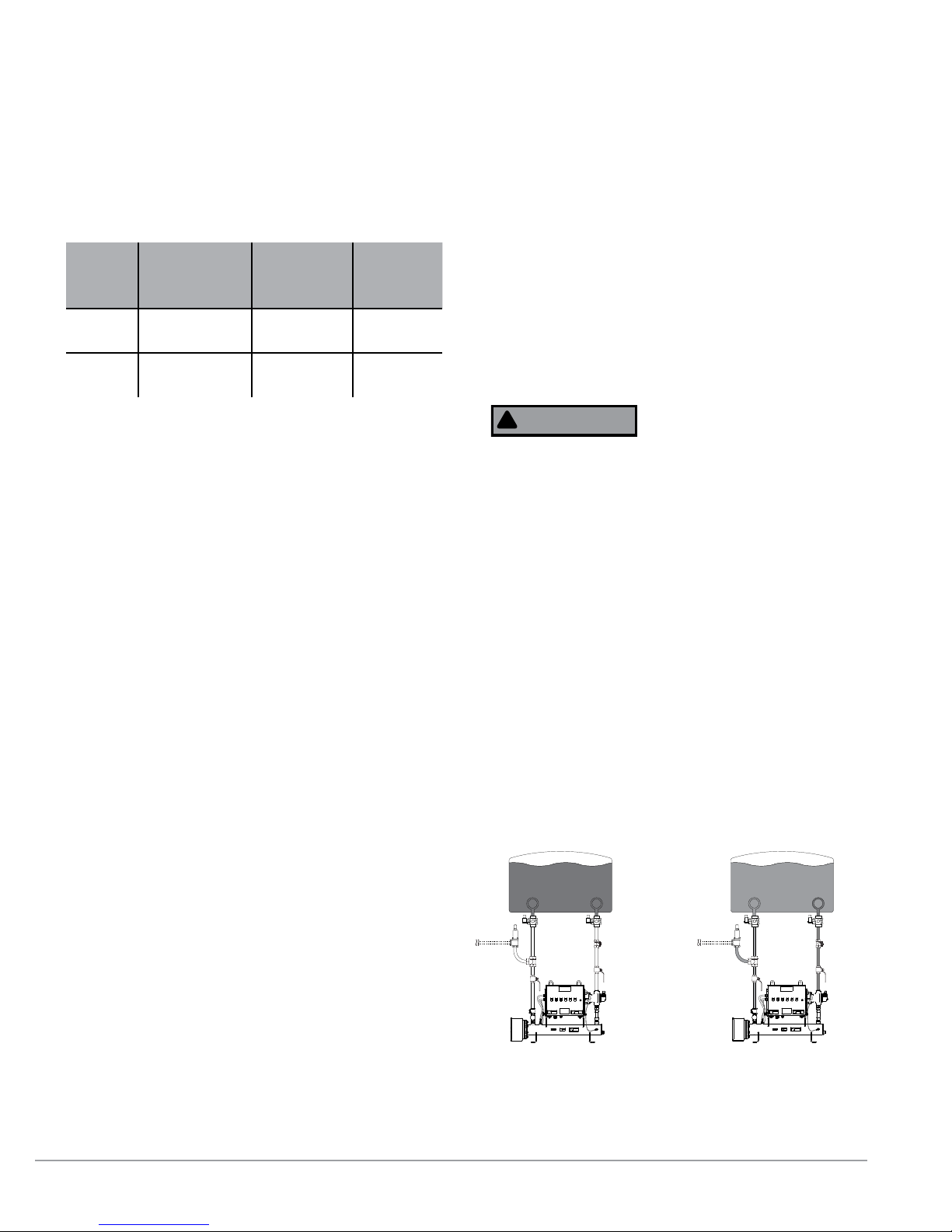
• An additional, user-supplied pressure relief
valve must be installed along the heating
system outlet plumbing. User-supplied
pressure relief valve plumbing must be
routed back to oil sump, oil tank or
atmospheric pressure. Do not route pressure
relief plumbing back to heating system tank.
See Fig. 3.
Table 1. HOTSTART recommended hose inner diameters,
line lengths and elbow counts for OXM/OGM oil supply lines.
Figure 3. OXM/OGM operation in a closed, pressured system.
When the pressurized system is active (left), solenoid valves isolate
the heating system from excessive pressure. When the system is in a
non-pressurized standby state (right), solenoid valves open.