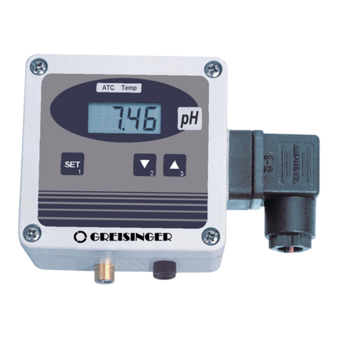
GREISINGER OXY 3610 MP User manual

.3X.6C
-07
Operating Manual
Dissolved Oxygen –
Measuring transducer
OXY 3610 MP
Keep for later use.
www.ghm-group.de
Companies / Brands of the GHM
Englisch

T02.0.3X.6C-07 Mounting and operating manual OXY 3610 MP Page 2 von 14
Contents
1SAFETY..................................................................................................................................................................... 3
1.1 GENERAL NOTE.....................................................................................................................................................3
1.2 INTENDED USE ......................................................................................................................................................3
1.3 QUALIFIED STAFF ..................................................................................................................................................3
1.4 SAFETY SIGNS AND SYMBOLS.................................................................................................................................3
1.5 REASONABLY FORESEEABLE MISUSE......................................................................................................................4
1.6 SUITABILITY ..........................................................................................................................................................4
1.6.1 During configuration ..................................................................................................................4
1.6.2 During normal operation............................................................................................................5
2PRODUCT DESCRIPTION........................................................................................................................................ 5
2.1 SCOPE OF SUPPLY.................................................................................................................................................5
2.2 TYPE PLATE ..........................................................................................................................................................5
3INSTALLATION AND COMMISSIONING.................................................................................................................6
3.1 GENERAL INSTALLATION INSTRUCTIONS..................................................................................................................6
4ASSIGNMENT OF ELBOW-TYPE PLUG.................................................................................................................7
5DISPLAY FUNCTIONS.............................................................................................................................................. 7
6CALIBRATION OF THE OXYGEN MEASURING TRANSDUCER..........................................................................8
7CONFIGURATION OF THE DEVICE........................................................................................................................8
7.1 CONFIGURATION PROCEDURE................................................................................................................................8
7.1.1 OFFSET “OFFS“..........................................................................................................................8
7.1.2 Average ambient absolute pressure “PABS“...............................................................................9
7.1.3 Display damping “FiLT“...............................................................................................................9
7.1.4 Save the last parameter values .................................................................................................9
8ERROR AND SYSTEM MESSAGES........................................................................................................................9
9OFFSET SETTINGS FOR DIFFERENT APPLICATIONS...................................................................................... 10
10 AMBIENT PRESSURE AS A FUNCTION OF THE ALTITUDE ABOVE SEA LEVEL.......................................10
11 OXYGEN ELECTRODE.......................................................................................................................................10
11.1 CONSTRUCTION OF THE SENSOR GWO 3600 ...................................................................................................10
11.1.1 General................................................................................................................................10
11.1.2 Design..................................................................................................................................11
11.2 WHEN IS ELECTRODE MAINTENANCE REQUIRED.................................................................................................11
11.3 ELECTRODE MAINTENANCE ..............................................................................................................................12
11.4 HOW TO OPERATE...........................................................................................................................................12
12 DECOMMISSIONING, RESHIPMENT AND DISPOSAL .................................................................................... 13
12.1 DECOMMISSIONING..........................................................................................................................................13
12.2 RESHIPMENT AND DISPOSAL.............................................................................................................................13
13 SPECIFICATION..................................................................................................................................................13

T02.0.3X.6C-07 Mounting and operating manual OXY 3610 MP Page 3 von 14
1 Safety
1.1 General note
Read this document carefully and get used to the operation of the device before you use it. Keep this document within
easy reach near the device for consulting in case of doubt.
Mounting, start-up, operating, maintenance and removing from operation must be done by qualified, specially trained
staff that have carefully read and understood this manual before starting any work.
The manufacturer will assume no liability or warranty in case of usage for other purpose than the intended one, ignor-
ing this manual, operating by unqualified staff as well as unauthorized modifications to the device. The manufacturer is
not liable for any costs or damages incurred at the user or third parties because of the usage or application of this de-
vice, in particular in case of improper use of the device, misuse or malfunction of the connection or of the device. Be-
stimmungsgemäße Verwendung
1.2 Intended use
Dissolved Oxygen-Measuring transducer converts an air oxygen-value in a 4-20 mA signal.
1.3 Qualified staff
For operating, running, maintaining and commissioning the device, the staffs needs to have an adequate level of
knowledge of both, the measuring and the meaning of measured values. This manual can be a valuable contribution.
All instructions have to be well-understood and complied with. To be sure that there is no risk arising due to misinter-
pretation of measured values, the operator must have further knowledge in case of doubt - the user is liable for any
harm/damage resulting from misinterpretation due to insufficient knowledge.
The manufacturer will assume no liability or warranty in case of usage for other purpose than the intended one, ignor-
ing this manual, operating by unqualified staff as well as unauthorized modifications to the device.
1.4 Safety signs and symbols
Warning notices are marked in this manual as shown below:
This symbol warns of imminent danger, death, serious injuries and significant damage to prop-
erty at non-observance.
This symbol warns of danger to living tissue and many materials, that can be damaged
or destroy by exposure to that chemical!
Achtung! Symbol warnt vor möglichen Gefahren oder schädlichen Situationen, die bei Nichtbe-
achtung Schäden am Gerät bzw. an der Umwelt hervorrufen.
This symbol points out processes which can indirectly influence operation or provoke unfore-
seen reactions at non-observance.
This symbol refers of using a eye protection, which protects the eyes from strong light, UV radia-
tion, laser, chemicals, dust, splitter or weather conditions.
This symbol refers of using protective gloves, which protects for mechanical-, thermal-, chemi-
cal-, biological- or electrical hazards.

T02.0.3X.6C-07 Mounting and operating manual OXY 3610 MP Page 4 von 14
1.5 Reasonably foreseeable misuse
This device must not be used at potentially explosive areas!
Do not use these products as safety or emergency stop devices or in any other application
where failure of the product could result in personal injury or material damage.
Failure to comply with these instructions could result in death or serious injury and material dam-
age.
This device must not be used at a patient for diagnostic or other medical
purpose
1.6 Suitability
This device has been designed and tested in accordance with the safety regulations for electronic devices. However,
its trouble-free operation and reliability cannot be guaranteed unless the standard safety measures and special safety
advises given in this manual will be adhered to when using the device.
1.6.1 During configuration
Caution, acid! The electrode contains KOH
KOH can cause severe chemical burns!
If there was contact:
• To skin: Flush contacted area with large amounts of water for several minutes.
• To clothing: remove contaminated clothing.
• To eyes: Flush with large amounts of water for at least 15 minutes, obtain medical treatment.
After swallowing:
• Give large volumes of water. DO NOT induce vomiting!
• Obtain medical treatment.
General instructions and safety regulations for electric, light and heavy current plants, including
domestic safety regulations (e.g. VDE), have to be observed.
Trouble-free operation and reliability of the device can only be guaranteed if the device is not
subjected to any other climatic conditions than those stated under "Specification". If the device is
transported from a cold to a warm environment condensation may cause in a failure of the func-
tion. In such a case make sure the device temperature has adjusted to the ambient temperature
before trying a new start-up.
This device only serves as supervision by the monitoring of essential or other for the customer
important systems.
It must not be used instead of compulsory approval monitoring devices and it is not designed for
that purpose. If this device is used for the monitoring of such systems on its own, the manufac-
turer will not assume liability for damages whatsoever.

T02.0.3X.6C-07 Mounting and operating manual OXY 3610 MP Page 5 von 14
1.6.2 During normal operation
Do not use this product as safety- or emergency- stop devices or in any other application where
failure of the product could result in personal injury or material damage.
Failure to comply with these instructions could result in death or serious injury and mate-
rial damage.
Whenever there may be a risk whatsoever involved in running it, the device has to be
switched off immediately and to be marked accordingly to avoid re-starting. Operator safety
may be a risk if:
-there is visible damage to the device
-the device is not working as specified
-the device has been stored under unsuitable conditions for a longer time
In case of doubt, please return device to manufacturer for repair or maintenance. With costs.
The conceptual design, particularly when connecting with other devices has to be done thor-
oughly.
Internal connections of other devices e.g. from ground with protective earth may lead to prohib-
ited voltage levels that could disturb the function, damage or even destruct the device or any
connected equipment. Never run the device with a damaged or faulty power supply.
2 Product description
2.1 Scope of supply
1 x Dissolved Oxygen-Measuring transducer
2 x GWO 3600-L04_MU
3 x KOH 100
3 x Mounting and operating manual OXY 3610 MP
Dissolved Oxygen-Measuring transducer
GWO 3600-L04_MU
2.2 Fehler! Verweisquelle konnte nicht gefunden werden.
Production date code
Article number
CE-mark see below:
Options
Disposal (s. Chapter
12.2)
Measuring range
Output signal
Please refer to
manual.
Power supply
Power supply
Manufacturer address
CE mark:
With the CE-Sign declares the manufacturer, that the Product is conform with the pre-
vailing requirements of EU.

T02.0.3X.6C-07 Mounting and operating manual OXY 3610 MP Page 6 von 14
3 Installation and Commissioning
3.1 General installation instructions
Loosen screws (A).
Remove cover (B)
Wall mounting screws (C) are not included.
The mounting-hole-diameter is 4.2 mm.
See pattern drilling above (50 x 70 mm).
Release the screw (a).
Unplug the connector.
Release the connection sealing, cable fitting
(b), shim (c) and sealing-ring (d).
Pull out the connection socket (f).
Thread cable through parts (b), (c), (d) and
into connector-housing (e).
To mount the connection cable 2-, 3-, or 4-
wire depending on type of device see chap-
ter 4 Assignment of elbow-type plug, the an-
gle plug screw has to be loosened.
Reattach part (f) in (e).
Reattach parts (d) and (c) and tighten (b).
Plug in the connector with connection sealing
and tighten (a).
Connect the ph electrode at the BNC socket
(I).
Connect the sensor at the 5 pole diode
Pattern drilling for
wall mounting
50 x 70 mm

T02.0.3X.6C-07 Mounting and operating manual OXY 3610 MP Page 7 von 14
4 Assignment of elbow-type plug
Description of the contacts.
2-wire connection (4-20mA)
1= supply voltage +Uv
2= GND / signal
3- wire connection (voltage)
1 = signal +
3 = supply voltage +Uv
(4) = supply voltage -Uv
signal -
4- wire connection (voltage)
1= signal +
2= signal -
3= supply voltage +Uv
(4)= supply voltage -Uv
5 Display functions
During normal operation the oxygen content is displayed in the unit [mg/l]. By pressing the Key 2 (down) the temper-
ature at the electrode can be shown, pressing key 3 (up) shows the state of the electrode in [%]. The state is calcu-
lated and stored during the calibration (see below). The displays of the state and the temperature of the electrode are
marked by small arrows at the upper end of the display. After 5 seconds the transducer display switches automatically
back to the oxygen value.
display dissolved oxygen
display electrode temperature
display state of electrode
1
2
A
Uv
V
3
Uv
1
VUv
3
1
2

T02.0.3X.6C-07 Mounting and operating manual OXY 3610 MP Page 8 von 14
6 Calibration of the oxygen measuring transducer
Expose electrode to the ambient air, wait until the temperature has adapted to the ambient conditions.
Parameter
button 1 <
5sec
Description
CAL
After approx. 10 sec’s the transducer is calibrated or a referring error message will be shown (see
below):
Display
Meaning
Possible fault causes
Remedy
CFE.1
Temperature out of allowed
range
Temperature has to be within 5
to 40°C
Calibrate again at correct temperature
Electrode error
Temperature sensing defective
Check cable & connection,
replace electrode if necessary
CFE.3
Wrong signal: to low
Membrane dried out/electrode
used up
Electrode maintenance / replace
CFE.4
Wrong signal: to high
Calibration surrounding not valid
Check Calibration surrounding
CFE.6
Instable signal
Calibration surrounding not valid
Check Calibration surrounding
Oxygen electrodes are sensitive components. Please read the referring manual prior to use.
During calibration the rating of the electrode is evaluated: 100% means perfect state, 40 % means e.g. sensor element
has a weak output signal and needs to be replaced soon (p.r.t. sensor manual). The electrode rating can be displayed
with key 3 (down).
7 Configuration of the device
For the correct function of the device in its application, it has to be configured to mean-
ingful settings. For doing this the cover has to be removed. Then the jumper J1 right
above of key 2 has to be set.
Select the value with button 2 (down) and 3 (up).
To save the value confirm with button 1 (set). Concurrent the new parameter value will
be invoked.
The device will start again after saving the last parameter value.
7.1 Configuration procedure
7.1.1 OFFSET “OFFS“
Parameter
button 1 <
5sec
Value
button 2 / 3
Description
OFFS
-1.00 0.00
The offset is entered in mg/l. It can be used to compensate different effects,
e.g. special
approaching flow conditions of the application. Please refer to Appendix A.

T02.0.3X.6C-07 Mounting and operating manual OXY 3610 MP Page 9 von 14
7.1.2 Average ambient absolute pressure “PABS“
Parameter
button 1
Value
button 2 / 3
Description
PABS
500 2000
Necessary for a correct evaluation of the state of the electrode. If the
application works for example at an altitude of 350 m above sea level,
980mbar is a correct setting. Please refer to chapter 10 Ambient pres-
sure as a function of the altitude above sea level.
7.1.3 Display damping “FiLT“
Parameter
button 1
Value
button 2 / 3
Description
FiLT
0 15.0
By this factor the ‘speed’ of the display can be adopted to the application. This
is intended to reduce instabilities in the measured value as they appear in
some specialised applications.
Enter the desired value by using keys 2 (down) and 3 (up). Input range: 0...15
(0: fast display, 15: slow display. Setting ex works: 10.
7.1.4 Save the last parameter values
Parameter
button 1
Value
button 2 / 3
Description
8888
8888
The values will be saved. The device will start again (The display is shown
8888).
Bring back the jumper j1 to the ‚parking position after configuration (one contact connected, the
second contact on air)!
Then the device can be calibrated by key 1 and the configuration data is protected.
8 Error and System Messages
Display
Description
Possible fault cause
Remedy
FE 1
measuring range exceeded
Calibration is wrong
Recalibrate the transducer.
FE 2
Measuring values below
measuring range
Wrong signal
Check the connections, cable and
electrode.
FE 7
System fault
Error in device
Disconnect from supply and reconnect.
If error remains: return to manufacturer
FE 9
Input signal is not valid
Sensor not connected or
cable defective
Temperature out of range
Check electrode, cable and connec-
tions
Check temperature
8.8.8.8
Segment test
The transducer performs a display test for 2 seconds after power up. Af-
ter that it will change to the display of the measuring.
Input signal is not valid
Sensor not connected
Check sensor, cable and connections
Permissible input range is ex-
ceeded
Check if not a wrong sensor is con-
nected.
Replace sensor.

T02.0.3X.6C-07 Mounting and operating manual OXY 3610 MP Page 10 von 14
-0,6
-0,4
-0,2
-1E-15
0,3 0,5 0,7 0,9 1,1 1,3 1,5 1,7 1,9
Offset [mg/l]
v [m/s]
9 Offset settings for different applications
The Offset setting is supposed to correct measuring deviations caused by different flow speed (v) around the elec-
trode:
For activated sludge basins and at flow speeds > 1m/s an offset
setting of ca –0.6 should be entered.
In between 0.3 and 1m/s the offset can be read from the dia-
gram. 0.3m/s correspond to the speed that is achieved by stir-
ring by hand.
Flow speeds below 0.3 m/s are not sufficient to get a correct and
reproducible measuring.
Für Belebtschlammbecken und bei Anströmungen > 1m/s sollte
ein Offset von ca. –0,6 eingegeben werden.
Zwischen 0,3 und 1m/s kann der Wert aus dem Diagramm aus-
gelesen werden. 0,3m/s entsprechen in etwa der Anströmung,
die beim Rühren per Hand erreicht wird.
Strömungsgeschwindigkeiten <0,3 m/s sind zu gering, um eine
genaue Messung zu gewährleisten.
10 Ambient pressure as a function of the altitude above sea level
Altitude über NN
[m]
Pabs [mbar)
Altitude über NN
[m]
Pabs [mbar)
-100
1025
900
909
0
1013
1000
898
100
1001
1200
877
200
989
1400
856
300
977
1600
835
400
966
1800
814
500
954
2000
794
600
943
2500
746
700
932
3000
701
800
920
4000
616
Values between are to be interpolated.
11 Oxygen electrode
11.1 Construction of the sensor GWO 3600
11.1.1 General
The oxygen electrode is an active electrode consisting of a silver cathode and a lead anode using potassium hydrox-
ide (KOH) as an electrolyte. In case of oxygen being present it will be reduced at the silver cathode and the electrode
produces electric current. In case of no oxygen being present not current will be produced. Both the silver cathode and
the lead anode will be used up during oxygen measuring. The electrode ages. We, therefore, recommend regular
maintenance of the electrode at monthly intervals (see 11.3 Electrode maintenance).
Attention when working with electrolyte!
The electrolyte is caustic! (strong base, KOH)
Avoid contact to skin, protect Your eyes.
Protective equipment is necessary!
Irritates the skin and the mucous membranes, caustic.
When contact with the eyes immediately clean with water at least for 15 minutes.
Consult a doctor!
The membrane is delicate –if damaged, caustic electrolyte gets lost and the sensor shows
wrong signal.
Make it a rule to always store the electrode in a humid environment.
- in the storage flask filled with water
- in another container filled with water
If electrode has not been used for some time, clean membrane with soft cloth and remove de-
posits, if any (algae, bacteria etc.).

T02.0.3X.6C-07 Mounting and operating manual OXY 3610 MP Page 11 von 14
11.1.2 Design
The electrode housing is made of ABS. With the exception of the electrode shaft all parts need to be maintained
regularly and be replaced if necessary.
o Protective flask: The protective flask is used to moisten the membrane. This prolongs service life of the electrode.
The protective flask contains water. Attention! Use water only; never use potassium chloride (KCI); this is only required
for storage of pH-electrode.
o Diaphragm head: The membrane head is covered with a Teflon membrane. It will be filled with KOH electrolyte and
screwed onto the electrode shaft (no air bubbles). Damages in the membrane, large air bubbles or air bubble rings in
the membrane head will result in erroneous measurements. This may also be the reason for errors in the calibration.
The membrane head is a spare part and can be ordered individually.
o Filling hole: If the electrode is used at high temperatures or if it has been stored without its protective flask for a
longer period of time, some electrolyte will be lost due to evaporation. Please refer to Refilling description below.
11.2 When is electrode maintenance required
Attention when working with electrolyte!
The electrolyte is caustic! (strong base, KOH)
Avoid contact with skin and eyes.
Protective equipment is necessary!
Irritates skin and mucous membranes, caustic.
In the case of contact with the eyes, immediately clean with clear water about 15 minutes
Eye protective is necessary!
Protective gloves are necesarry when filling the electrode! Do not touch the electrolyte with your
bare hands. When contact with the skin immediately clean with water at least for 15 minutes.
Electrode shaf
Diaphragm
Replenishing hole
Protective flask

T02.0.3X.6C-07 Mounting and operating manual OXY 3610 MP Page 12 von 14
Unless it is used the electrode is to be stored in the protective flask filled with water or directly in a vessel filled
with dechlorinated water.
Residues of bacteria, fungi or algae must be removed prior to measuring using a soft paper towel.
If a calibration can no longer be carried out or if the membrane is damaged the electrode needs maintenance.
In the course of the time air bubbles may accumulated underneath the membrane. As long as they are small and
do not affect the silver cathode the measurements will not be influenced. If, however, there is a large ring of air
bubbles underneath the membrane covering the silver cathode, the electrode needs maintenance.
11.3 Electrode maintenance
Prepare liquid absorbing paper towel.
Remove membrane head and wipe off electrolyte solution with paper cloth.
Do not touch electrolyte. If your skin has come into contact with electrolyte, rinse thoroughly with clear water.
Clean silver cathode using sand paper (grain size 240). Do not shine silver cathode as its surface needs to be
rough so that the electrolyte can be dispersed evenly. Remove any dust from grinding.
If necessary, take out replenishing screw and top up with electrolyte till it is spilling out (e.g. using a disposable
syringe). Put back replenishing screw. (Normally not necessary).
Put new membrane head on the paper towel and fill up with electrolyte making sure there are no air bubbles.
Put electrode into head vertically from above till the thread catches. Then take up head with paper towel and
screw onto electrode from underneath. Electrolyte will be displaced from the membrane head, flowing over.
Mop up excess electrolyte using paper towel.
Turn electrode around and check for air bubbles. If there are no air bubbles or only tiny ones the maintenance
has been completed. If there are large air bubbles the process has to be repeated.
If O-ring has been damaged, it has to be replaced.
Prior to its being calibrated again the electrode needs to be lying on a table for at least 3 hours.
If electrode can no longer be calibrated although it has been properly maintained, the electrode
needs to be returned to manufacturer for check-up and may have to be replaced.
11.4 How to Operate
Store the oxygen electrode always in water, either in the protective flask or directly in a vessel filled with
dechlorinated water. For storage in the protective flask first push the cap on the electrode second the o-ring and
thereafter put the electrode in the flask and screw the cap down the flask.
If the diaphragm has dried up the electrode must be soaked in water for approx. 2 h prior to measuring start-up.
Then a calibration can be carried out without any problems.
The electrode is only suitable for the devices OXY3610MP. Unsuitable devices may lead to the destruction of the
measuring device and the oxygen electrode!
For measuring remove the protective flask of the electrode.
The electrode measurement is sensitive against shocks!
By stirring of the electrode in the measured liquid be careful that the electrode does not hit the con-
tainer. A vibration of the electrode has an effect to the measured value.

T02.0.3X.6C-07 Mounting and operating manual OXY 3610 MP Page 13 von 14
12 Decommissioning, Reshipment and disposal
12.1 Decommissioning
Always disconnect the device before from its supply before decommission e.g. at fuse. Valid general safety require-
ments shall be observed.
Please also make sure that connected Loads are disconnected also and are in a safe state.
12.2 Reshipment and disposal
Alle Geräte, die an den Hersteller zurückgeliefert werden, müssen frei von Gefahrstof-
fen sein. Gefahrstoffe am Gehäuse können Personen oder die Umwelt gefährden.
Verwenden Sie zur Rücksendung des Geräts, insbesondere wenn es sich um ein noch funktio-
nierendes Gerät handelt, eine geeignete Transportverpackung.
Legen Sie dem Gerät das ausgefüllte Rücksendeformular der GHM-Homepage unter
http://www.ghm-messtechnik.de/downloads/ghm-formulare.html bei.
Das Gerät darf nicht über die Restmülltonne entsorgt werden.
Senden sie das Gerät an uns zurück (ausreichend frankiert, siehe auch Hinweise oben).
Wir entsorgen das Gerät sachgerecht und umweltschonend.
13 Specification
Measuring range
0.00 …25.00 mg/l dissolved oxygen
Output signal
See 2.2 Fehler! Verweisquelle konnte nicht gefunden werden.
Accuracy:(at nominal temperature)
Approx. 2 years at nominal condition
Display
±1.5% of measured value ±0.2 mg/l
Output signal
±0.2 % FS
Connection
4 - 20 mA (Zweileiter)
Spannung (Dreileiter bzw. Vierleiter)
Add. output signal
±0.2 % FS
Auxiliary energy: (supply voltage)
Uv = 12 - 30 V DC (4-20mA)
Uv = 18 - 30 V DC (0-10V)
or see 2.2 Fehler! Verweisquelle konnte nicht gefunden werden.
Reverse voltage protection
50V permanent
Perm. impedance (at 4-20mA)
RA(Ohm) < (Uv - 12V) / 0.02A )
Example: for Uv = 18V
RA< (18V - 12V) / 0.02A => RA< 300 Ohm
Permissible load (at 0-...V)
RL(Ohm) > 3000 Ohm
Electrode
Special oxygen electrode GWO3600MU (in scope of supply!)
Electrode type
active diaphragm type, with integrated NTC resistor
Response time
95% in 10 sec., depending on temperature
Operation life
3 years or more, depending on proper maintenance
Operating pressure
max. 3 bar
Mounting diameter
Ø 12,0 ±0,2 mm (also suitable for ½" glanding)
Length
approx. 220 mm (incl. anti-buckling glanding), Mounting length: approx.
110 mm
Elektrodenanschluss
5 polige verschraubbare Diodenbuchse
Temperature compensation
automatic, 0 ... 50 °C
Electrode
Special oxygen electrode GWO3600MU (in scope of supply!)
Electrode type
active diaphragm type, with integrated NTC resistor
Response time
95% in 10 sec., depending on temperature
Operation life
3 years or more, depending on proper maintenance
Operating pressure
max. 3 bar
Mounting diameter
Ø 12,0 ±0,2 mm (also suitable for ½" glanding)
Length
approx. 220 mm (incl. anti-buckling glanding), Mounting length: approx.
110 mm

T02.0.3X.6C-07 Mounting and operating manual OXY 3610 MP Page 14 von 14
GHM GROUP –Greisinger | GHM Messtechnik GmbH
Hans-Sachs-Str. 26 | 93128 Regenstauf | GERMANY
Phone +49 9402 9383-0 | Fax +49 9402 9383-33
Storage temperature
-20 ... 70 °C (electrode 0 ... 60 °C)
Housing
ABS (IP65 - with the exception of electrode and temperature probe con-
nection sockets)
Dimensions
82 x 80 x 55 mm (without elbow-type plug and sensor sockets)
Mounting
With fixing holes for wall mounting (in housing - accessible after cover
has been removed).
Mounting distance
50 x 70mm, max. shaft diameter of mounting screws is 4 mm
Electric connection
Elbow-type plug conforming to DIN 43650 (IP65),
Max. wired cross-section 1.5 mm², cable diameter 4.5 to 7 mm.
Directives / standards
The device confirm to following European directives:
2014/30/EU
EMC directive
2011/65/EU
RoHS
Applied harmonized standards
EN 61326-1 : 2013
Emission level: Class B
EMI immunity according to table 1
Additional error: <1%
Table of contents
Other GREISINGER Transducer manuals
Popular Transducer manuals by other brands

Furuno
Furuno Airmar TM258 Owner's guide and installation instructions

Lumel
Lumel P43 user manual

controlair
controlair 500-BD Installation, operation and maintenance instructions

Ametek
Ametek 953N Series Configuration manual

Camille Bauer
Camille Bauer Gossen MetraWatt SINEAX DME 401 operating instructions

Audio Precision
Audio Precision APx1701 Series installation instructions