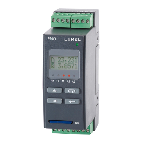
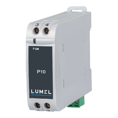
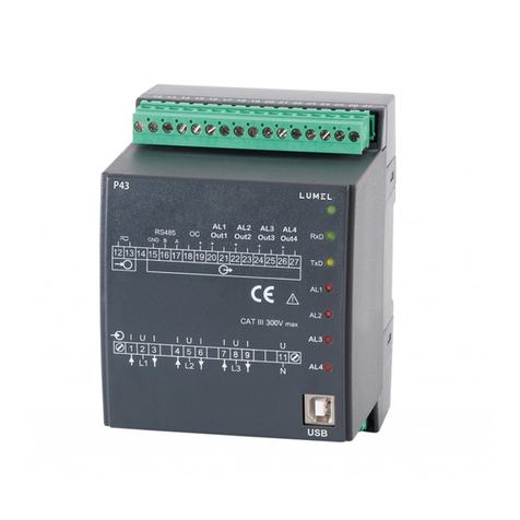
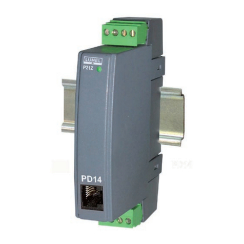
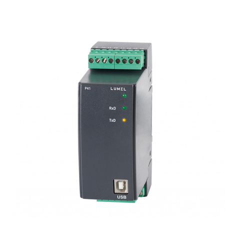
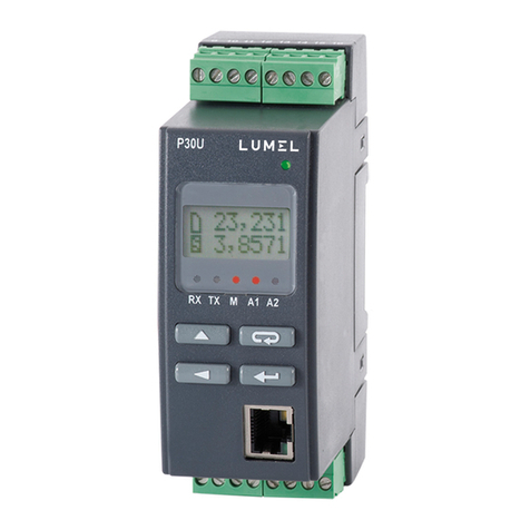
Lumel P43 User manual

1
TRANSDUCER
OF NETWORK
PARAMETERS
P43 TYPE
USER’S MANUAL

2

3
Contents
1. Application ...................................................................... 5
2. Transducer Set ................................................................. 6
3. Basic Requirements and Operational Safety .............................. 6
4. Installation ...................................................................... 7
5. Service .......................................................................... 12
6. Archive - Power Profile ....................................................... 30
7. Error Codes ..................................................................... 30
8. Serial Interfaces ............................................................... 31
9. Examples of P43 Transducer Programming ............................... 40
10. Technical Data ................................................................. 43
11. Execution Codes ............................................................... 46
12. Maintenance and Guarantee ................................................ 47

4

5
1. APPLICATION
The P43 transducer is a programmable digital instrument destined for
the measurement and parameter conversion of 3 or 4-wire three-phase
power networks, in balanced and unbalanced systems.
It ensures the measurement and conversion of measured values into
standard analog current signals. Two relay outputs signal the overflow
of selected quantities, and the pulse output can be used for the con-
sumption monitoring of the 3-phase active energy.
Quantities measured and calculated by the transducer:
phase voltages ...................................................... U1, U2, U3
phase–to-phase voltages ..................................... U12, U23, U31
3-phase mean voltage .......................................... U
phase-to-phase mean voltage ............................. UPP
three-phase mean current..................................... I
phase currents ..................................................... I1, I2, I3
phase active powers ............................................. P1, P2, P3
phase reactive powers .......................................... Q1, Q2, Q3
phase apparent powers ........................................ S1, S2, S3
phase active power factors................................... Pf1, Pf2, Pf3
reactive/active ratio of power factors .................... tgM1, tgM2,tgM3
three-phase mean power factors .......................... Pf, tgM
three-phase active, reactive and apparent powers ... P, Q, S
active mean power (e.g.15 min.)........................... Pav
three-phase active and reactive energy ............... Ept, Eqt,
frequency ............................................................. f
The transducer possesses an archive, in which 1000 last mean power
values suitably synchronized with the clock (15, 30 or 60 minutes) are
stored.
Maximal and minimal values are measured for all quantities. Additional-
ly, there is the possibility to accommodate the transducer to external
measuring transducers. The transducer has a detection and signaling
of incorrect phase sequence. The actualization time of all accessible

6
2. TRANSDUCER SET
The set of the P43 transducer is composed of:
- P43 transducer 1 pc
- user’s manual 1 pc
- guarantee card 1 pc
- CD disc 1 pc
When unpacking the transducer, please check whether the type
and execution code on the data plate correspond to the order.
quantities does not exceed 1 second. All quantities and configuration
parameters are accessible through the RS-485 interface and the USB
interface.
Transducer output signals are galvanically isolated from the input
signal and the supply. Outside the transducer, there are socket-plug
3. BASIC REQUIREMENTS AND
OPERATIONAL SAFETY
In the safety service scope, the transducer meets to
requirements of the EN 61010-1 standard.
Observations Concerning the Operational Safety:
All operations concerning transport, installation, and
commissioning as well as maintenance, must be carried out by
qualified, skilled personnel, and national regulations for the
prevention of accidents must be observed.
Before switching the transducer on, one must check the
correctness of connections to the network.
Before removing the transducer housing, one must switch the
supply off and disconnect measuring circuits.

7
4. INSTALLATION
4.1. Fitting
The P43 transducer is adapted to be mounted on a 35 mm rail acc. to
EN 60715.
The overall drawing and the fitting way are presented on the fig.1.
Fig.1 Overall Dimensions and Transducer Fitting Way.
The removal of the transducer housing during the guarantee
contract period may cause its cancellation.
The P43 transducer is destined to be installed and used in
industrial electromagnetic environment conditions.
One must remember that in the building installation, a switch or a
circuit-breaker should be installed. This switch should be located
near the device, easy accessible by the operator, and suitably
marked.

8
4.2. External Connection Diagrams
Semi-indirect mea-
surement in a three-
wire network
Direct measure-
ment in a three-wire
network

9
Indirect measurement with the use of
3 current transformers and 2 or 3 voltage
transformers in a three-wire network.
Fig. 2. Connection Diagrams of the Transducer in a Three-wire Network
Caution: In industrial environment with high electromagnetic
noises, it is recommended to earth the terminal 11.

10
Semi-indirect
measurement
in a four-wire
network
Direct measurement
in a four-wire network

11
Indirect measurement with the use of 3 current
transformers and 2 or 3 voltage transformers in a
four-wire network
Fig. 3. Connection Diagrams of the Transducer in a Four-wire Network

12
5. SERVICE
Frontal Plate Description
Fig. 4 Frontal view of the P43 transducer
Messages after Switching the Supply on
After switching the supply on, the state diode should light up for a moment
in red, and next should light up in green. The recording confirmation in
registers is signaled by a short extinction of the state diode.
The incorrect work is signaled by the state diode in the way described
in the chapter 7. The data reception through the RS-485 interface is
signaled by a pulsing of the Rx diode. The data transmission through
USB link for
configuration
Transducer
state diode
Diode of data recep-
tion through RS-485
Diode of data
transmission through
RS-485
Diodes of AL1 and
AL2 alarms

13
the RS-485 interface is signaled by a pulsing of the Tx diode.
The switching of the relay 1 on causes the lighting of the AL1 diode,
however the switching of the output 2 on causes the lighting of the AL2
diode (fig. 4).
Installation of COM Port Controllers in the Computer
The P43 transducer makes use of the software, which creates in the
system, a device of Universal Serial Bus – P43 transducer of network
parameters, and connected to it, the virtual COM port named P43
transducer of network parameters.
The controller installation in the Windows system causes the addition of
a successive serial COM port to the list of ports serviced by the operat-
ing system.
After connecting the transducer to the USB port, the operating system
informs about the appearance of a new device by means of the message
presented on the fig. 5.
The creator to find a new hardware of the Universal Serial Bus will be
started automatically. One must act in compliance with the creator sug-
gestions, choosing the installation from the indicated location and giving
the path to controllers being in the added CD. Controllers are compatible
with following systems: Windows 2000, XP, Server 2003, Vista, server
2008, (x86 and X64). When installing controllers, information about the
lack of the controller digital signature can occur. One must ignore this
information and carry on the installation.
Fig. 5. Message signaling the detection of a new device “Transducer
of P43 type”.

14
After the successful ending of the installation, the system will inform
about the installation of a new device (fig. 7.). Two new devices ap-
pear in the device manager – Transducer P43 and Port COM named:
Transducer P43, acc. to the fig. 8.
Fig. 7. Systemic message ending the installation of P43 controllers
After closing the creator, the system detect immediately the succes-
sive device – USB Serial Port (fig. 6.). The creator for detection a new
hardware will start again.
Fig. 6. Systemic message concerning the detection of a new device

15
Fig. 8. View of the device manager window together with the installed
P43 transducer, which the port COM6 is assigned to.
Transducer Configuration by Means of the LPCon
Software
The LPCon software is destined for the configuration of the P43 trans-
ducer. One must connect the transducer to the PC computer through
the PD10 converter or directly through the USB link and after choosing
the Option-> Connection configuration, configure the connection (fig.
9.). For direct connection, through USB: address 1, baud rate 9600 kb/s,
mode RTU 8N2, timeout 1000 ms and the suitable COM port under which
the controller of the P43 transducer has been installed or through the
RS-485 interface and the PD10 programmer: address, baud rate, and
the mode acc. to the installed in the transducer.

16
Fig. 9. Configuration of the connection with the P43 transducer
After the connection configuration, one must choose from the Device ->
Transducers -> P43 menu, and next click the Readout icon in order to
read out all parameters. One can also read out parameters individually
in each group, clicking the Refresh button. In order to change parame-
ters, one must write the new value in the parameter window and click
the Apply button.

17
Setting of Transmission Parameters
After choosing the group – transmission parameters, it is possible to
configure following elements:
a) address – address for the communication with the P43
transducer through the RS-485 interface from the range
1...247. The value 1 is normally set up by the manufacturer.
b) baud rate – the communication rate through the RS-485
interface from the range (4800, 9600, 19200, 38400 bit/sec.)
The value 9600 is set up by the manufacturer.
c) transmission mode – The transmission mode through the
RS485 interface from the range (RTU 8N2, RTU 8E1,
RTU 8O1, RTU 8N1). The transmission mode is normally
set up on RTU 8N2 by the manufacturer.
Fig. 10. View of the configuration window of transmission parameters

18
Fig.11. View of the configuration window of measurement parameters
Setting of Measurement Parameters
After choosing the group: ratios, power synchronization, time, follo-
wing elements can be configured (fig. 11.):
a) current transformer ratio. The multiplier is used to
recalculate the current in the transformer primary
side. It is set up on 1 by the manufacturer.
b) voltage transformer ratio. The multiplier is used to
recalculate the voltage in the transformer primary
side. It is set up on 1 by the manufacturer.
c) way to synchronize the mean power:
- 15 minutes’ walking window – mean power PAV
will be recalculated for the last 15 minutes, actualized
every 15 seconds, i.e. walking window,
- measurement synchronized with the clock every 15, 30
or 60 minutes - mean power PAV will be actualized every
15, 30 or 60 minutes synchronized with the external real
clock (fig. 12).
It is set up on the walking window by the manufacturer.

19
Erasing of Watt-hour Meters and Extremal Values
After choosing the group: erasing of watt-hour meters and extremal
Values, following commands are possible to carry out (fig. 13):
a) erasing of watt-hour meters. All watt-hour meters of active
and reactive energy are erased,
b) erasing of active mean power. The power archive is additio
nally erased, the number of measurements is set up on 0.
c) erasing of min. and max. values. The currently measured
value is copied out to the minimal and maximal value.
Fig. 13. View of the window to erase watt-hour meters.
Fig. 12. Measurement of the 15 minutes’ active mean power synchro-
nized with the clock.
d) current time. Time in the form hh:mm:ss. It is set up on
0:00:00 by the manufacturer (also after the supply decay).

20
Table 1
Setting of alarm parameters
After choosing the group: alarm 1 configuration or alarm 2 configura-
tion, it is possible to configure following alarm parameters (fig. 15):
a) assignment of the alarm output parameter – kind of signal, on
which the alarm acc. to the table 1 has to react,
The set of the input quantity for alarms and analog outputs is included in
the table 1. The calculation way is shown in examples in the chapter 9.
Value in reg-
isters 4010,
4015, 4020,
4026
Kind of quantity
Value for percentage calcula-
tion of alarms and output
values
00 Lack of quantity /alarm or analog
output switched off/ Lack
01 Voltage of phase 1 Un [V] *
02 Current in the wire of phase L1 In [A] *
03 Active power of phase L1 Un x In x cos(0°) [W] *
04 Reactive power of phase L1 Un x In x sin(90°) [var] *
05 Apparent power of phase L1 Un x In [VA] *
06 Coefficient of active power of
phase L1 1
07 Coefficient tgMof phase L1 1
08 Voltage of phase 2 Un [V] *
09 Current in the wire of phase L2 In [A] *
10 Active power of phase L2 Un x In x cos(0°) [W] *
11 Reactive power of phase L2 Un x In x sin(90°) [var] *
12 Apparent power of phase L2 Un x In [VA] *
13 Coefficient of active power of
phase L2 1
14 Coefficient tgMof phase L2 1
15 Voltage of phase 3 Un [V] *
16 Current in the wire of phase L3 In [A] *
17 Active power of phase L3 Un x In x cos(0°) [W] *
18 Reactive power of phase L3 Un x In x sin(90°) [var] *
Other manuals for P43
1
Table of contents
Other Lumel Transducer manuals
Popular Transducer manuals by other brands

Gems
Gems GT-RK1 manual

Thyracont
Thyracont VSP63E operating instructions

Atlas Copco
Atlas Copco IRTT-B 1A-I06 user guide

MAMAC SYSTEMS
MAMAC SYSTEMS EP-313 installation instructions

S+S Regeltechnik
S+S Regeltechnik PREMASGARD 711x Series Operating Instructions, Mounting & Installation

WT sensor
WT sensor PCMPT01 Series quick start guide