WIKA CPD8500 User manual

Utility Manual
EN
CPD8500 EMM calibration sled
© 10/2018, Mensor, LP. All rights reserved.
Mensor is a registered trademark of Mensor, LP.
All other brand and product names are trademarks or registered trademarks of their respective companies.
Prior to starting any work, read the operating instructions!
Keep for later use!
Transducer utility manual 0020646001

II WIKA operating instructions EMM Calibration Sled
PN 0019408001A 08/2018 EN
EN
Contents
Contents
1. Introduction 3
1.1 Equipment required . . . . . . . . . . . . . . . . . . . . . . . . . . . . . . . . . 3
1.2 Technincal information: . . . . . . . . . . . . . . . . . . . . . . . . . . . . . . . 3
2. Program operation and procedures 4
2.1 Calibration Procedures . . . . . . . . . . . . . . . . . . . . . . . . . . . . . . . . 4
2.2 Software installation . . . . . . . . . . . . . . . . . . . . . . . . . . . . . . . . . 4
2.3 Use of multiple calibration methods . . . . . . . . . . . . . . . . . . . . . . . . . . . 7
2.4 Additional features . . . . . . . . . . . . . . . . . . . . . . . . . . . . . . . . . 8

3
WIKA operating instructions EMM Calibration Sled
PN 0019408001A 08/2018 EN
EN
1. Introduction
1. Setup
Calibration sled kit EMM assembly
Assembled calibration sled Calibration sled to EMM connection
1.1 Technincal information:
The Mensor EMM assembly has four sensing devices built in to the device. Sensors included are ambient temperature, relative
humidity, barometric pressure and precision platinum resistive thermometer (PRT).The rated accuracies are:
Initial Accuracy Stability
Ambient Temperature .4°C 2°C /year
Relative Humidity 3% 2% /year
Barometric Pressure .25% 2% /year
PRT .2°C 1°C /year
■It is important to use standards that have a test uncertainity ratio of at least 1:1. A higher ratio is better.
1.3 Equipment required
■EMM Calibration Sled - P/N 0019780001
■EMM - P/N 0019582001
■CPD8500 EMM Cal Sled application software - P/N 0020646001
■Pressure Standard capable of 1.1 bar abs pressure
■Temperature standard 0 to 50°C
■Humidity standard 0 to 100% RH
■Temperature calibration bath 0 to 50°C

4WIKA operating instructions EMM Calibration Sled
PN 0019408001A 08/2018 EN
EN
1. Setup
2. Program operation and procedures
2.1 Calibration Procedures
1. Connect EMM to sled as shown on page 3. Apply power.
2. Start EMM Calibration program. It should appear as shown in Figure 2.1.
Figure 2.1 – Main screen
3. Set Com Port to your computers com port value.The baud rate settings are built into the application. They are 57600, N, 8, 1.
The Com Test button brings up the window below. If the EMM is not connected or a problem exists an error will be shown.
Figure 2.2 A – Successful com test Figure 2.2 B - Communication error
1.2 Software installation
To install the software, run the setup program on the included disk (setup.exe). The setup program will install all the necessary
files to run the program. It will register all files appropriately so it can be completely removed using the Windows® add/remove
program. Upon installation, a desktop shortcut and start menu shortcut will be added. If this is not necessary, the “Xducer_Utility.
exe” program may be run directly.
The computer on which the software is run must have Windows® XP or greater. It must have an available RS-232 serial port
capable of running at 57600 baud. Finally, Microsoft .NET Framework 4.0 or greater must be installed. This is included as the file
“dotNetFx40_Full_x86_x64.exe”. The latest version can be downloaded from: http://www.microsoft.com/net
Calibration Sled Hardware Setup: Connect the AC adapter of the power supply to an AC power socket. Then connect the power
supply to the circular power connector on the rear of the calibration sled. Connect the 9 pin d-sub connector on the calibration sled
to any available RS-232 connector on the computer. This connection is made through the straight 9 pin male to 9 pin male cable.
Transducer Com Cable Setup: Connect the AC adapter of the power supply to an AC power socket. Then connect the “Computer”
side of the cable to any available RS-232 connector on the computer. Connect the “Transducer” side of the cable to the EMM
communication port.

5
WIKA operating instructions EMM Calibration Sled
PN 0019408001A 08/2018 EN
EN
3. Program operations and procedures
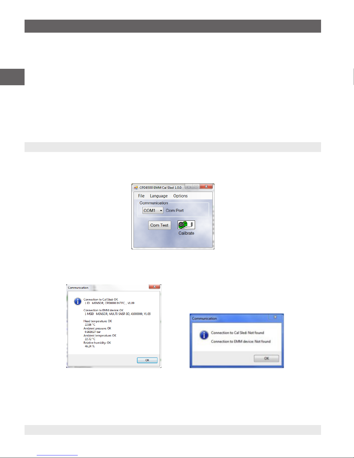
4. Select Calibrate button.The next screen should appear as shown in Figure 2.3.
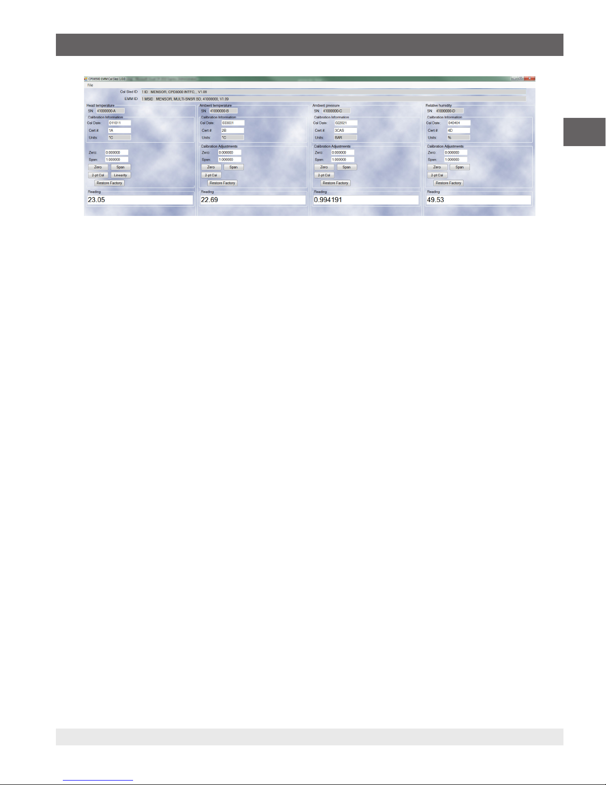
Figure 2.3 – Calibration/data screen
The following fields may be updated:
• Calibration Date – a six digit number must be entered. The calibration date entered should be formatted in the form “MMDDYY”
or “DDMMYY” so that the Mensor instrument will convert the date correctly for the different locales available from the supported
languages.
• Cert # – a 16 character string can be entered. The Cal ID# is an arbitrary string you may use to identify the calibration of the
sensor.
• Units – Displays the native units of the sensor
• Zero – a value between ± 0.1% of range, usually close to 0. This is the calibration offset used to adjust the zero reading of the
sensor. The zero offset is unit based so enter the value in the native units of the sensor.
• Span – a value between 1 ± 0.15% of range, usually close to 1.0. This is the calibration correction multiplier used to adjust the
span reading of the sensor.
5. The tool is divided into four separate sections corresponding to each sensor in the EMM.
• Head temperature is the Platinum Resistive Thermometer (PRT) for head temperature measurement that has an external probe.
• Ambient Temperature is the internal ambient temperature sensor.
• Ambient Pressure is the internal barometric pressure sensor.
• Relative Humidity is the internal humidity sensor.
Observe each reading to determine if sensors are live.
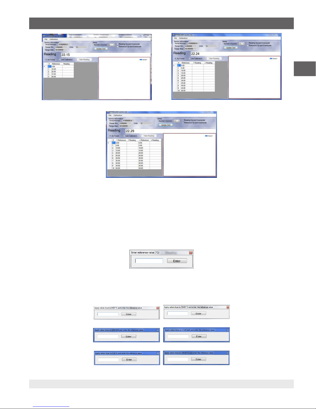
6. The PRT should be calibrated by probe immersion in a precision temperature bath against a standard that has accuracy as
previously described. Multiple choices exsist for calibration. Including forced zero and/or span adjustment with the same named
buttons.The 2-pt Cal is a way to calibrate at two discrete tempertures. Linearity is a way to calibrate multiple discrete temperture
points and auto-linearizing the PRT.
7. All other sensors can be calibrated using the Zero, Span or 2-pt Cal buttons.
⇒Considering the accuracy requirements of these sensors, at Mensor we find that a simple single point calibration using the
Zero button under ambient conditions is sufficient.
8. If pressure is to be applied to the barometric sensor for calibration, tubing and an adaptor fitting have been provided. One end
of the tubing is inserted into the hole in the EMM’s case. The tubing can then be applied over the sensor barb. The other end of the
tubing can be connected to a pressure source with the adaptor fitting. The adaptor fitting has a 7/16-20 male thread
Head temperature linearity
Selection of the linearity button brings up the following screen.

6WIKA operating instructions EMM Calibration Sled
PN 0019408001A 08/2018 EN
EN
3. Program operation and procedures
Figure 2.4 – Linearization correction
Enter reference values and actual measured values into table.This process can be semi-automatic by selecting Live Calibration
entering the reference value then selecting the Take Reading button. A graph is updated as the points are entered. When the table
is fully populated select “Calibration” and “Save Calibration”.The linearity correction will be applied and saved.
Figure 2.5 –Linearity correction graph
Other options are available such as reducing the number of calibration points and upscale-downscale calibrations. By changing the
Number of points and selecting Update Grid fewer test points can be used.

7
WIKA operating instructions EMM Calibration Sled
PN 0019408001A 08/2018 EN
EN
Figure 3.9 A - 5 points selected Figure 3.9 B - Reading upscale and downscale
Figure 3.9 C - Reference and reading upscale and downscale
⇒Note: At any point these processes can be aborted and the Factory Restore button can be selected. This will revert the
calibration back to the factory settings.
2.2 Use of multiple calibration methods
⇒Note: All entries should be followed by a carriage return for values to be accepted.
Zero or Span buttons:
■Zero can be used to force an offset in the value shown by entering a value in the same units for example °C.
⇒THE ZERO BUTTON SHOULD BE USED FOR SINGLE POINT CALIBRATIONS.
■Span can be used to change the slope. This value is nominally 1. This is a multiplier such that 1 would not change the current slope. A
value of 0.9 would multiply the current slope by 0.9 or 90%. The Zero and Span window is shown in Figure 4.
Figure 2.6 - Zero and Span window
2-pt cal:
Use of the 2-pt Cal button requires the capability to apply two discrete calibration stimuli to the individual sensors.
A reference value near the zero point of the sensor should be entered. When the Enter button is selected the application will read
the sensor’s value and automatically make the correction. The same applies to the next point. It is important that the reference
stimulus be close to the “Apply” value shown. The 2-pt Cal windows are shown below.
Figure 2.7 A - Displays for both temperatures sensors
Figure 2.7 B - Displays for both barometric pressure sensors
Figure 2.7 C - Displays for both relative humidity sensors

88WIKA operating instructions EMM Calibration Sled
PN 0019408001A 08/2018 EN
WIKA Alexander Wiegand SE & Co. KG
Alexander-Wiegand-Straße 30
63911 Klingenberg • Germany
Tel. +49 9372 132-0
Fax +49 9372 132-406
info@wika.de
www.wika.de
Mensor Corporation
201 Barnes Drive
San Marcos, TX 78666 • USA
Tel. (+1) 512 3964200-15
Fax (+1) 512 3961820
E-Mail sales@mensor.com
www.mensor.com
Other manuals for CPD8500
1
Table of contents
Other WIKA Transducer manuals
Popular Transducer manuals by other brands

HBM
HBM P8AP operating manual

Rockford Fosgate
Rockford Fosgate IBeam IB-200 Installation and operation

Fishman
Fishman SBT-C installation guide

Daiichi Electronics
Daiichi Electronics WTT2-92A-12 instruction manual

Humminbird
Humminbird MEGA 360 IMAGING Series installation guide

Balluff
Balluff BTL7-A505-M Series Condensed guide