Gremon Trutina Hydro User manual

2 www.gremonsystems.com
Contents
1. Introduction
1.1 About this document
1.2 Marks system
2. Content of the package
3. Additional accessories necessary for installation
3.1 Summary
3.2 List of additionalaccessories
4. Steps of installation
4.1 Preparation
4.1.1 Electricity
4.1.2 Internet connection
4.2 Mounting the gutter
4.3 Installation of the Trutina
4.4 Installation of the 100 kg sensors on the gutter
4.5 Installation of the 10 kg sensors
4.6 Installation of the 25 kg sensor
4.7 Connection of Ethernet cable
4.8 Power on
4.8.1 Steps of first start
4.8.2 Operations, LEDs

3 www.gremonsystems.com
1. Introduction
1.1 About this document
This document is a summary about the installation and setting up the Trutina system, issued by Gremon
Systems Ltd. Further information is provided at www.gremonsystems.com.
1.2 Marks system
Various icons and visually displaying images can be found in the document in order to guide the reader and
also to highlight the importance of a given part. The symbols used in the document have the following
meaning:
This symbol indicates some useful information or tip within the paragraph.
This symbol refers to content which may require increased focus.
This symbol refers to a step-by step list. In case of these paragraphs a process of setting is
shown, please pay attention to the correct order.
2. Content of the package
●Trutina web application
●Trutina measuring unit
●Power supply
●Fixing kit
●Sensors (Trutina Hydro)
-3 pcs 10 kg plant sensor
-1 pc 25 kg plant sensor
-2 pcs 100 kg gutter sensor
●Sensors (Trutina Soil)
-5 pcs 10 kg plant sensor
-1 pc 25 kg gutter sensor

5 www.gremonsystems.com
3 pcs 10 kg sensor
1 pcs 25 kg sensor
2 pcs 100 kg sensor
3.Additional accessories necessary for installation
3.1 Summary
Installation consists of two steps. First we need to separate a section of plants so that we can measure them.
Then we need to fix the Trutina unit and its additional accessories to the suitable place of the separated part.
The aim is to create a well-separated scales system, that is to create the suitable conditions for the smooth
running of measurement.
Besides the Trutina, the following accessories are necessary for the installation. These accessories need to
be procured separately. Further information on the procurement of these accessories can be found at
www.brinkman.com.
3.2 List of additional accessories
Gutter: length depends on the place of installation. The system will measure the weight of the plants placed
on this gutter. The length of the gutter is determined by the distance between the balusters in the path
selected as the place of the measurement.

6 www.gremonsystems.com
It is advisable to cut the gutter 10-05 cm shorter than the distance
between the balusters in order to make the mounting easier.
Technical aids: The following accessories are necessary to fasten the gutter. When fixing, place the gutter in
the gutter-holding triangle and fasten it to an upper stabile point of the structure of the greenhouse. The
suitable pitch (2-3%) is provided with the help of the turnbuckle. These accessories can be replaced with
others tailored to your needs.
Gutter-holding triangle
Turnbuckle
Hook

7 www.gremonsystems.com
Wire-rope
Shackle
4.Steps of installation
4.1 Preparation
4.1.1 Electricity
To the operation of the scales you will need electricity at 230V / 50 Hz, but the power supply also supports
the range of voltage between 100V-240V (50Hz/60HZ). The cable of the power supply is 2 m long, so the
electrical socket needs to be placed within this distance from the power suppply. The power supply of the
Trutina needs to be carried out with the help of a socket with IP44 degree of protection. The socket must be
placed outside the irrigaton zone. The cable between the power supply and the device is 1.5 m long so the
maximum distance between the power supply and the device cannot be longer than 1.5 m.
4.1.2 Internet connection
To operate the Trutina it is vital to have suitable internet connection. The device is equipped with a cable
connection point so during the preparation the routing of a UTP/FTP cable with internet connection must be
provided. The end of the cable must be supplied with a connector, type RJ-45. The length of the cable cannot
be more than 90 metres. If the device is placed farther than 90 m, the insertion of an active switch is also
necessary.

8 www.gremonsystems.com
It is advisable to use good quality, outdoor cable, type CAT5e/CAT6 FTP or
SFTP and connectors type FTP RJ-45 in the greenhouses in order to avoid any
electrical interference.
CAT5e FTP cable
FTP UTP connector
If there is no possibility to build up a cable connection in the growing facility, setting up the device with
wireless connection is also feasible. This can be done with the help of a wireless bridge. A wireless access
point needs to be installed at the place of the nearest internet connection, then a client station needs to be
set up, the cable side of which is connected to the Trutina. Further information on the configuration of this
solution can be found at www.gremonsystems.com.
Cable connection to the Trtuina
The device can communicate with 3G / 4G modem as well, because it
does not require high bandwith.

9 www.gremonsystems.com
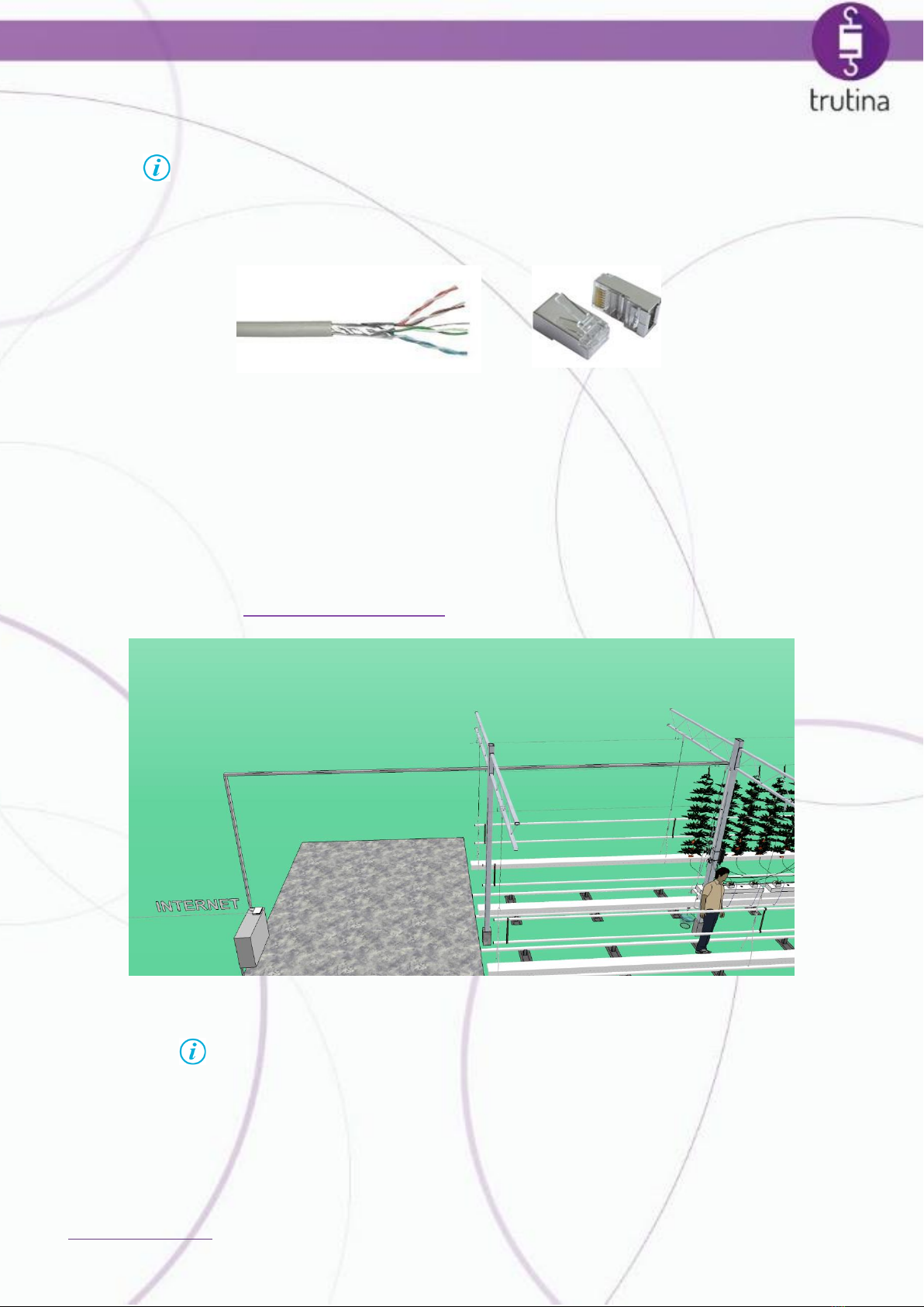
The realization of wireless bridge to the Trutina
In case of cable connection the length of the cable cannot exceed 90 m. In
case of wireless connection creating a stable link is of utmost importance. To
set up wireless connection, please consult your IT expert.
4.2 Mounting the gutter
In connection with the attributes of the gutter further information can be found at point 3.2. If it is not
possible to provide a gutter with the suitable length, it can be replaced with other type of supportive
structures (e.g. wooden ramp). In case of the replacement of the gutter it is important that the replacement
structure should be suitably stable in order to be able to support the plants.
When mounting the gutter, it is essential that the structure hang without any support and the supporting
wires and other fixtures should not touch any objects about. For hanging use the technical aids detailed at
3.2, but these can be replaced on demand.
To fix the gutter, the wire-ropes need to be fastened to the truss (up, at the top of the greenhouse) with the
help of the hook. Then the turnbuckle needs to be fixed to the end of the wire-rope. It is necessary so that
you could change the angle of the gutter. Finally, the gutter-holding triangle needs to be fastened under the
turnbuckle. It will hold the gutter or its replacement item.

10 www.gremonsystems.com
The 100 kg sensor will be placed between the turnbuckle and the gutter-holding
triangle. The sensor can be placed after fixing the measuring unit, so it is advisable to
leave the gutter loose, unloaded. Information on setting up the 100 kg sensors can be
found at 4.4.
It is advisable to fix the gutter with help. Be careful when moving the plants in
order to avoid causing any harm.

11 www.gremonsystems.com
Placement of gutter
4.3 Installation of the Trutina
To fix the Trutina and the power supply the baluster of the greenhouse is the most suitable place. The
strength of the fixing must be taken into consideration so that the it could hold the devices. It is advisable to
fix the Trutina low on the baluster to make the future maintenance easier. The shadow of the plants protects
the device from direct sunshine as well.
Suitable fixing of the Trutina

13 www.gremonsystems.com
Fixing the Trutina requires increased attention to avoid any damage to the
sensors and the cables. Unsuitable load of the sensors or their collision can
cause harm to the device and can result in destorted measurement data.
4.4 Installation of the 100 kg sensors on the gutter
Placement of the 100 kg sensors is needed in case of the device Trutina Hydro. Two of the 100 kg sensors of
the Trutina need to be hanged between the turnbuckle and the gutter-holding triangle at the end of the
hanged gutter.
When hanging the 100 kg sensors make sure the structure hang unobstacled and the distance between it
and the gutter system should be at least 20 mm.
Suitable hanging of the sensors

14 www.gremonsystems.com
The distance between the gutter and the gutter system belowit should be at least 20 mm.
4.5Installation of the 10 kg sensors
High degree of attention is needed during the installation of the sensors. The weight marked on the sensors
means their maximum load. The 10 kg sensor can be loaded with maximum 10 kg, while the 100 kg sensor
can be loaded with maximum 100 kg.
The system develops a technical fault when overloaded.
Pay attention to the free hanging of the sensors. The cables should not strain. In case of defective suspension,
the weight of the cable may be included in the measurement, burdening the sensor to varying degrees when
the cables move. This may result in faulty recording of data.
Right placement of the sensor:
Inappropriate placement of the sensor:

15 www.gremonsystems.com
The 10 kg sensors must be hanged on
the place of the hooks of the plants
taking part in the measurement.
The hooks supporting the plants
must be hanged on the sensors.
When the plants are lowered, the
sensor needs to be relocated
according to the technology and the
hook must be placed back on the
sensor.

16 www.gremonsystems.com
It is advisable to place the sensors in a way that the plants advance in the direction of the Trutina.
Alternatively, the sensors move away (together with the plants), so as soon as the sensor cables start to
strain they must be hanged on another plant. But the frequent change of the plants undermines the
validation of the measurement.
Placement of 10 kg sensors

17 www.gremonsystems.com
Placement of sensors
4.6 Installation of the 25 kg sensor
Besides measuring the weight of the plants, the 25 kg sensor can also be used for measuring the amount of
the irrigation water. If.a plant is measured with it, instructions about its used are found at point 4.5. In case
it is used for measuring irrigation water, it must be hanged on the bottom of the gutter with a bucket or an
another type of container loaded with maximum 25 kg.
Attention! The 25 kg sensor can be loaded with maximum 25 kg.
Overloading the sensor will result in its failure.

19 www.gremonsystems.com
Working Trutina system
4.7Connection of the Ethernet cable
The water-protected coupling ball needs to be fixed to the RJ-45 connector at the end of the prepared UTP
cable. This cable end needs to be connected to the connector at the bottom of the device. Make sure you
tighten it (click).
Fixing the water-protected coupling ball

20 www.gremonsystems.com
4.8Power on
4.8.1 Steps of first start
At the beginning of the start the device connects to the internet. When switching on, make sure that the
cable is connected and the network connection is working properly.
After installation, the device is started following the steps below:
1. Complition of all installation tasks
2. Checking the network, connection of the cable
3. Switching on with plugging in of the electric socket
4.8.2 Operations, LEDs
LEDs show whether the device is working properly.
Meaning of LEDs:
Green LED: if you see the green light, the device is on.
Operation of the Red LED:
oHaving switched on, the LED shows the red light continuously. This shows that the checking of
the connection has been started.
oThen the LED starts blinking.showing that the device is searching for network connection.
oIf the LED is showing the red light continuously again, the device is ready to run.
oIf the LED does not start showing the red light after the blinking, there is some problem with
connectivity.
LEDs at the bottom of the device
Table of contents