Phaserunner Controller User Manual
Rev 2.0
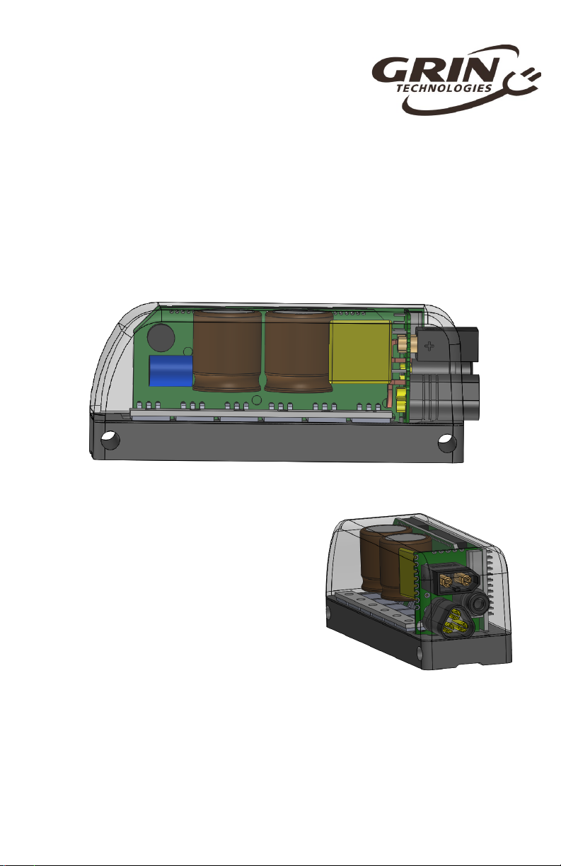
3 Installation and Mounting
The Phaserunner is esigne to be narrow in
wi th an has a channel own the back of the
heatsink so that it can be strappe to your bicycle
tubing with a pair of cable ties. When mounte
externally like this, the controller is expose to
abun ant air flow for cooling an the on-off button
remains accessible.
If you want to install the controller insi e a vehicle
chassis, then the aluminum heatsink shoul be
bolte irectly to a metal plate via the 4 mounting
holes in or er to help with heat issipation.
Otherwise it will be more prone to overheating
an going into thermal rollback at high currents.
If the controller running at full 96A an is mounte to a bike tube expose to
airflow, it will hit thermal rollback after 1-2 minute an then settle to ~50 amps of
stea y state phase current. When bolte to a large external heatsink, the thermal
rollback at full current will take longer to kick in (4-6 minutes) an will level off at
aroun 70 amps of phase current.
4 Parameter Tuning
If you purchase the Phaserunner as part of a complete kit package with a
motor, battery etc. then most likely the ven or will have alrea y preconfigure the
controller parameters so you can just plug things in an go.
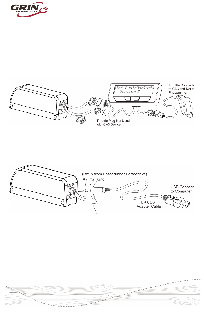
Otherwise, for your first run you will want to have the Phaserunner plugge into
your battery pack an motor, with a computer or laptop nearby that has the
Phaserunner software installe .
The Phaserunner software is available for Linux, Win ows, an MacOS from our
webpage:
http://www.ebikes.ca/pro uct-info/phaserunner.html
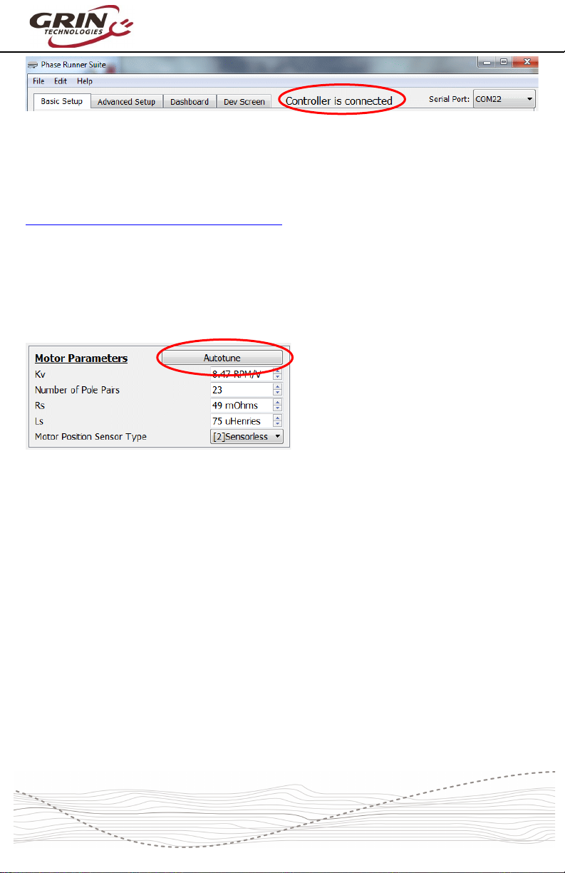
Plug in the TTL->USB cable to link your computer to the Phaserunner, with the
Phaserunner turne on. When you launch the Phaserunner software, the status
isplaye on the top bar shoul then say “Controller is connecte ”.