Grin Cycle Analyst V3.1 User manual

Cycle Analyst V3.1
Official User Manual
Grin Technologies Ltd
Vancouver, BC, Canada
ph: ( 04) 5 9-0902
email: [email protected]
web: http://www.ebikes.ca
Copyright © 2019

Cycle Analyst V3.1 User Manual
Rev 1.0
Table of Contents
1 Introduction...................................................................................3
2 High Level Operation....................................................................3
3 Installation....................................................................................4
3.1 Handlebar Wiring.....................................................................................4
3.2 Shunt / Controller Wiring.........................................................................6
4 Display Screens.............................................................................7
4.1 ain Display..............................................................................................7
4.2 Diagnostics Screen, Display #12...............................................................8
4.3 Wh/km, Display #4....................................................................................9
5 esetting the Trip Counter............................................................9
6 Setup Menu..................................................................................10
6.1 Accessing and Navigating the Setup enu ...........................................10
6.2 Setting the Speedometer..........................................................................11
6.3 Setting Up the Battery.............................................................................14
6.4 Throttle Input Settings............................................................................17
6.5 Output Throttle Settings.........................................................................19
6.6 Setup Speed Limits..................................................................................19
6.7 Setup Power Limits.................................................................................20
6.8 Setting Up PAS or Torque Sensors........................................................21
6.9 PAS Configuration..................................................................................22
6.10 Temperature Sensor..............................................................................24
6.11 Setup Auxiliary Control Inputs............................................................25
6.12 Setup Ebrakes and Regen. ...................................................................27
6.13 Set Current Sense Shunt Resistance....................................................28
6.14 Using Presets..........................................................................................30
6.15 Display Customization..........................................................................31
7 Data Logging...............................................................................31
8 Software Setup Utility .................................................................33
9 Common Mistakes.......................................................................34
10 Enjoy your ide and emember to eset..................................35
11 Specifications.............................................................................36
2

Cycle Analyst V3.1 User Manual
Rev 1.0
1Introduction
Thank you for the purchase of a V3 Cycle Analyst device, Grin's latest model of
open standard display and control device for ebikes and other electric vehicles.
This document should help you get reasonably familiar ith the basic setup and
operation of a CA3 as part of your vehicle system.
2High Level Operation
The V3 Cycle Analyst is not like a typical ebike display interface that
communicates ith one particular model of motor controller. Instead the CA3 is
designed as a more universal display and control unit. To achieve this
universality, it reads existing signals already present in most EV drives to sense
the po er and speed of the vehicle, and then it regulates the motor po er
through a common throttle signal.
This is an important concept to understand; the CA3 does not "communicate"
ith your ebike in the same manner as proprietary display units. Rather it taps
into analog signals already present inside a motor controller and interprets them.
It then sends hat it thinks is the most appropriate throttle voltage to your
controller for generating a target amount of po er from the motor.
As far as your motor controller kno s, the V3 Cycle Analyst is just a throttle
device. The CA3 can't change any internal controller settings, or make the
controller do anything more than hat you could do via deft manipulation of a
normal throttle.
3

Cycle Analyst V3.1 User Manual
Rev 1.0
3Installation
The Cycle Analyst includes a handlebar bracket that allo s it to clamp on any
tube from 21mm (7/8”) to 40mm (1.5”) in diameter. You can mount it directly on
the handlebar, or you can s ivel the base 90 degrees and clamp it to the stem
for a more central display that doesn’t consume bar real estate. There is also an
optional steer tube mounting bracket and a ¼” threaded insert on the bottom of
the enclosure for improvised attachments.
If you have a CA3-DPS device hich uses an
external spoke magnet and separate speedometer
sensor, then you ill need to scre the spoke
magnet to your heel and zip-tie the sensor pickup
to your fork so that the magnet passes ithin about
5mm from the middle of the pickup sensor. To avoid
glitches in the speed reading, the sensor body
should be perpendicular to the direction of magnet
motion.
3.1 Handlebar Wiring
It is important that you ire up your throttle to plug into the Cycle Analyst rather
than directly to your motor controller. The CA3 has a short cable bundle for all
accessories and the throttle input is the black 3-pin connector. Your throttle
should be attached to this plug.
You can also connect ebrake cutoffs, auxiliary inputs, a temperature sensor, and
Pedal Assist (PAS) or torque sensors if you have them to the appropriate
connectors on CA3, but the throttle is the most essential for basic operation.
4

Cycle Analyst V3.1 User Manual
Rev 1.0
There are t o additional short cables coming out of the Cycle Analyst. One is an
1/8” TRS communications jack that can be used for data logging or connecting to
a computer for firm are updates and setting changes. The other is a DC Po er
cable that has full battery voltage for po ering front ebike lights, DC-DC
converters, and other peripherals that can run directly off pack voltage.
This DC po er tap is fused internally and is limited to 1 amp. It is shipped ith a
rubber protective cap and you should leave this cap in place if you are not using
the connector, as there is full battery voltage present on the exposed connector
pin.
We include a stretchy fabric Velcro sleeve that lets you cover up the connector
assembly for a clean finished look on the front of your bike once everything has
been plugged in. This sleeve also provides a convenient place for bundling up
any excess cable length.
5

Cycle Analyst V3.1 User Manual
Rev 1.0
3.2 Shunt / Controller Wiring
For systems that have a CA3 compatible motor controller, the electrical hookup is
simply a matter of connecting the 6-pin CA plug to the mating plug on the
controller. This JST-SM connector standard has pins for the battery voltage,
throttle signal, speedometer signal, and current sense resistor leads.
If your controller doesn't have a compatible CA plug on it, then you ill need to
use the Stand Alone Shunt ired inline ith the + and – battery leads in order for
the CA to see the battery current and voltage.
The Stand Alone CA3 Shunt has a short unterminated cable ith 3 signal ires
in it. The green signal ire is the throttle output of the Cycle Analyst, and that
should be ired to the throttle input plug of your motor controller. Without this
connection, the CA3 can monitor and display speed and battery consumption but
has no ay to regulate and control the motor po er.
The CA3 turns on henever there is voltage on the CA plug. With direct plug
connections, if the controller has an on/off s itch this ould also turn the CA on
and off. If the controller does not have an on/off s itch or the Stand Alone CA
shunt is used, then the the battery itself should have an on/off s itch for turning
the CA on and off.
Please refer to section 6.13 about setting the Cycle Analyst Rshunt value,
especially if you are connecting the CA3 directly to a motor controller.
6

Cycle Analyst V3.1 User Manual
Rev 1.0
4Display Screens
When the device is po ered up you can scroll through numerous display screens
by pressing the left and right buttons to sho you things of interest:
Table 1: Summary of CA3.1 Display Screens
Display #1, Main Screen Summary of battery level, speed, power, voltage, distance etc.
Display #2, Electrical nly View of just t e battery voltage, current, power, and amp- ours
Display #3, Human Power S ows pedal cadence and uman power if torque sensor installed
Display #4, Wh/km Battery watt- ours and energy consumed per km or mile
Display #5, Human Stats Average uman power, pedal cadence, and total uman energy output
Display #6, % Regen S ows regenerative amp- ours and % by w ic it as extended your range
Display #7, Peak Stats S ows peak current, peak regen current, and battery voltage sag
Display #8, Speed Stats Maximum and average trip speed and total trip time
Display #9, Temp Stats S ows current, average, and maximum temperatures if sensor is attac ed
Display #10, dometer S ows bot current trip distance and lifetime odometer
Display #11, Batt Info C arge cycle count, total kW energy used, and Battery internal resistance
Display #12, Diagnostics Live readout of t rottle input/output voltages and active limiting flags
Most of the essential information you ould ant hile riding is on Display #1.
4.1 Main Display
The battery State Of Charge (SOC) icon on the top left is a graphical indication of
the charge level in your battery pack, inferred from a combination of the cell
chemistry, pack voltage, and amp-hour consumption. This gauge ill only be
accurate if the battery type and series cell count has been set up correctly.
Next to that is the actual pack voltage. We recommend paying attention to your
battery voltage and becoming familiar ith the value that it sho s on a full
7

Cycle Analyst V3.1 User Manual
Rev 1.0
charge, during use, and hen the battery goes flat. This is often your first clue to
anomalous behavior and provides very useful troubleshooting information.
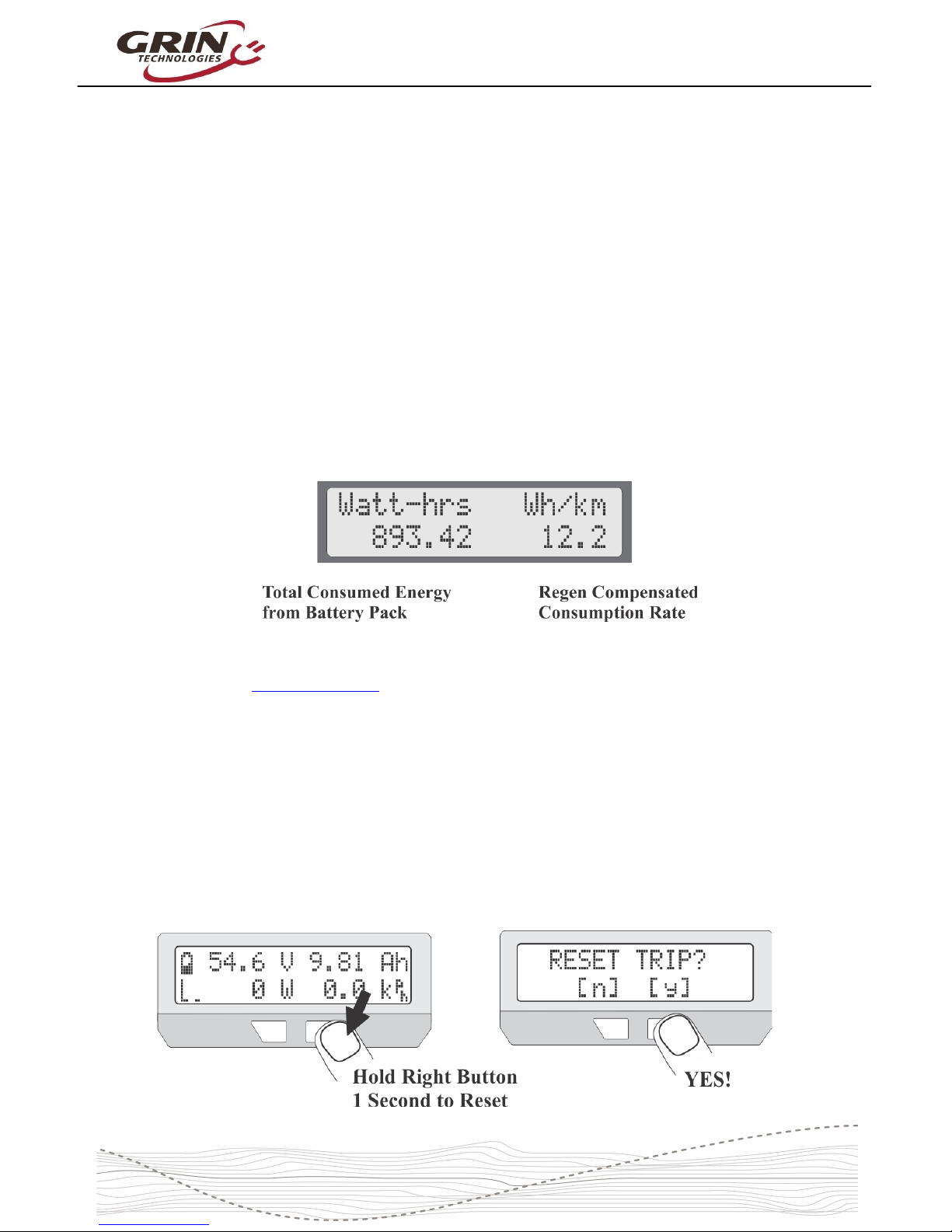
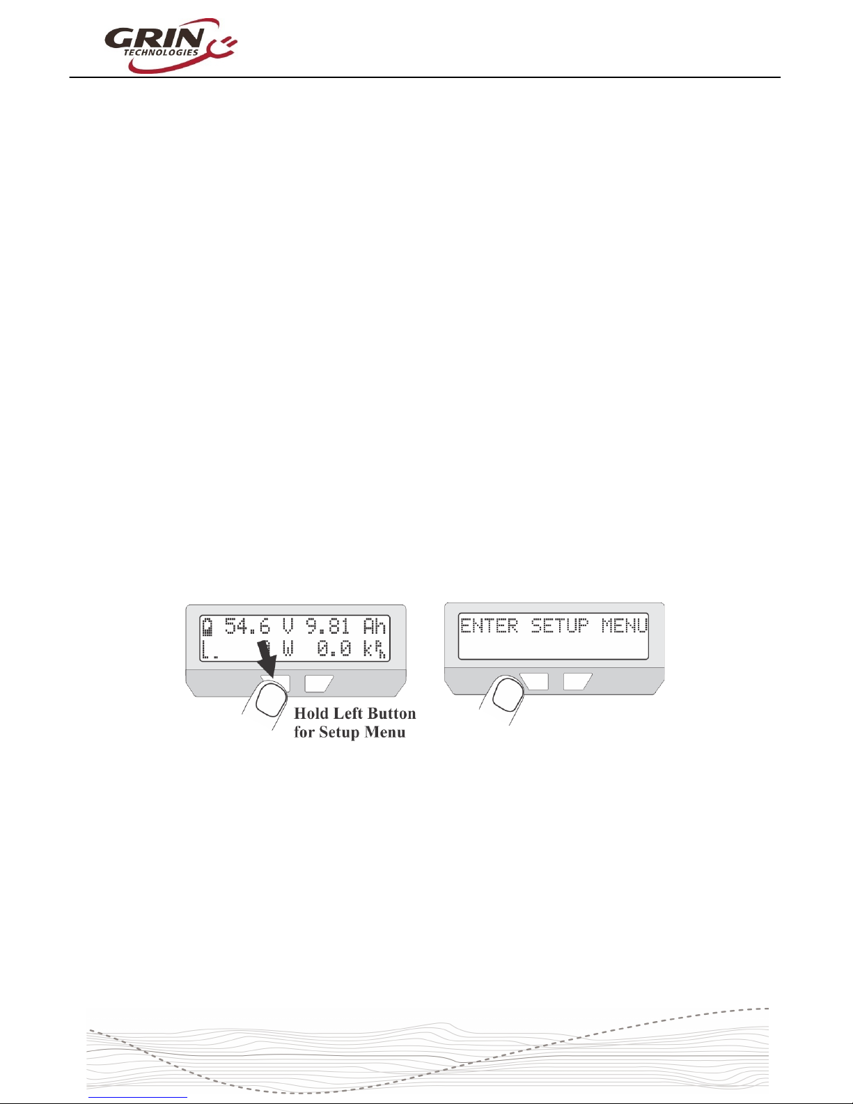
The top right is a customizable display field. By default, this toggles bet een
sho ing your accumulated amp-hours and distance since the last trip reset, but it
can be configured to sho other things like motor temperature, instantaneous
h/km, pedal cadence and so forth. You ill eventually find the consumed amp-
hours to be among the most useful and important pieces of information on the
CA display, but only if you remember to do a trip reset each time there is a fresh
charge on the battery pack.
The bottom left of the display has a throttle position that moves up and do n ith
the user's throttle signal going into the Cycle Analyst. This is replaced by an
animated brake lever if the ebrake cutoffs are engaged. Just beside this slider is
an animated Pedal Assist bar graph, hich is only active if you have a PAS
sensor and visually indicates ho fast or hard you are pedaling.
The bottom left numeric display by default sho s the electrical po er currently
flo ing through the system, and ill go negative during regenerative braking. It
is possible to change this to display amps instead of atts if you prefer.
Finally, on the bottom right is a readout of your current vehicle speed, in either
kph or mph as chosen in the setup menu.
The left and right buttons ill scroll through other display screens that sho
specific information that may be of interest. These screens are explained in detail
on the CA3 eb page and any of them can be hidden from vie if desired. The
diagnostics screen and att-hour screen are of particular interest though.
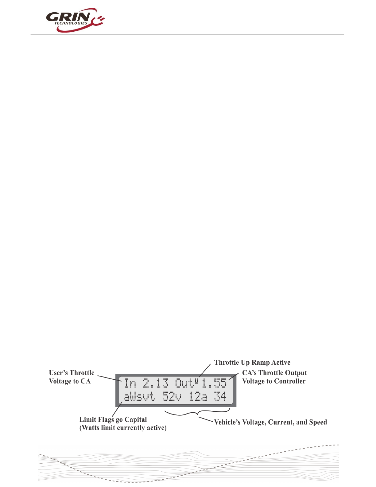
4.2 Diagnostics Screen, Display 12
If you press the left button once from the main display, you ill have the
diagnostics display. This can be invaluable during any kind of system
troubleshooting. The top line sho s the actual throttle voltage signal going into
the CA3, as ell as the throttle voltage going out to your motor controller. If the
rate of change of the throttle is being clamped, then the associated rate limit ill
sho up (F = fast, U = up, P = PAS, D = do n, see section 6.5).
8

Cycle Analyst V3.1 User Manual
Rev 1.0
The bottom left sho s if any of the limit settings are actively regulating the
throttle output voltage. Letters awvst refer to the Amps, Watts, lo Voltage,
Speed, and Temperature rollbacks, and they become capitalized hen active.
This display lets you easily identify if your input throttle is orking correctly, if the
CA itself is sending an output throttle to the motor controller, and if that output
throttle is being clamped by any of the programmed limit settings.
4.3 Wh/km, Display 4
The 4th display screen sho s the total energy in att-hours taken from the
battery, as ell as the average att-hours used per distance traveled, either
h/km or h/mi. This is one of the most useful statistics to check as it is the
equivalent of fuel mileage for your electric vehicle. You can see ho different
riding styles and terrains affect your energy usage, and you can compute ho
large of a battery ill be required to travel a given distance.
The other 9 displays are largely self explanatory and are more thoroughly
covered on the CA3 info page.
5Resetting the Trip Counter
If there is only one thing to remember about using the Cycle Analyst, it is that you
ill ant to make a habit of resetting the Cycle Analyst every time you have a
fresh charge in the battery. Do this by pressing and holding the right button until
the message "RESET TRIP?" sho s on the screen. This allo s you to see your
consumed battery amp-hours on each trip and ensures that the battery cycle
statistics are accurate.
9

Cycle Analyst V3.1 User Manual
Rev 1.0
If you forget to reset, the trip amp-hour, att-hour, and distance accumulators ill
eventually peg at their maximum values and you'll stop accumulating ne
statistics. You also on't get the benefit of seeing an accurate battery charge
cycle count, seeing trip to trip variation in your h/km consumption stats, and
learning exactly ho many amp-hours the battery is able to deliver.
If you press the reset button on certain other display screens, it ill reset just the
statistics associated ith that screen, like a reset of just the peak statistics or just
the temperature data.
6Setup Menu
If you received your CA3 as part of a complete ebike kit package then it should
be pre-configured ith reasonable values for that setup and be ready to ride.
There should be little need to change anything. If it as received as an
independent device and not as part of a kit package, then there is a good chance
that you ill need to change a number of settings in the CA3’s setup menu for it
to function ith accurate readings. Most essential ould be the heel size,
battery details, and Rshunt value.
6.1 Accessing and Navigating the Setup Menu
The Setup Menu is accessed by pressing and holding the left button.
Once you are in the setup menu, the left and right buttons allo you to scroll
through the options or toggle digits up and do n. Pressing and holding the
buttons has a special effect.
Hold the RIGHT button to enter a menu or save a setting (like pressing
enter on a keyboard).
Hold the LEFT button to exit something (like pressing escape on a
keyboard).
The setup page is organized ith all the related settings grouped into sub-
menus. Each of these high level menus is summarized in the table belo .
10

Cycle Analyst V3.1 User Manual
Rev 1.0
Table 2: CA3.1 Setup Menu rganization
Setup Speedometer Configure Speedometer Sensor (w eel diameter, #poles, metric/imperial)
Setup Battery Configure Battery Details (c emistry, #cells, low voltage rollback etc)
Setup Throttle Input Configure Input T rottle Mapping (min/max range, t rottle mode, autocruise)
Setup Throttle utput Configure CA's Output T rottle (min/max range, ramp limits, voltage/RC Pulse)
Setup Speed Limits Set various Speed Limits and associated PID feedback parameters
Setup Power Limits Set maximum power and current limits, and feedback gain parameters
Setup PAS Device Set PAS or Torque Sensor parameters (#poles, fwd/rev direction, torque signal)
Setup PAS Configuration Configure ow t e CA responds to pedal RPM and torque input from rider
Setup Temperature Sensor Configure motor Temperature Sensor type and max temperature limits
Setup Analog Aux Control Setup be avior of potentiometer or 2/3 position switc for Limit Control
Setup Digital Aux Control Setup be avior of 2-button up/down Digital Limit Control
Setup Ebrake Configuration of Brake Cutoff be avior and proportional regen
Setup Calibration Calibration parameters for voltage scaling, zero offset, and Rs unt
Setup Presets Enable up to t ree Mode Presets for quick access to pre-configured limits
Setup Display ptions Customize Display be avior, ide screens, c oose custom views
Setup Miscellaneous Ot er parameters like data log rate, display averaging, default saving
Setup Lifetime Statistics Total Lifetime c arge cycles, kilowatt ours, and odometer distance
6.2 Setting the Speedometer
The first item in the setup menu is your speedometer configuration. The second
line of the setup menu sho s a previe of the configured settings, including the
number of pulses per heel revolution, the programmed heel diameter, and
your preference of metric or imperial display.
What you may not notice on this previe line is the small heel sensor arro
beside the number of poles, hich sho s the signal going into the CA’s
speedometer input. With a spoke magnet and sensor this arro should s itch
do n henever the magnet is right by the sensor. If you have a CA3-DP device
11

Cycle Analyst V3.1 User Manual
Rev 1.0
using the hall sensors for heel speed, then it ill toggle up and do n many
times as you turn the heel. Most setup menus provide a previe of the related
signals seen by the CA hich can be valuable for setup and troubleshooting.
To change any of these settings, press and hold the RIGHT button to enter into
the speedometer setup menu.
6.2. Metric / Imperial Units
The first item you may ant to change in the speedometer setup menu is your
preference for metric or imperial units. This is edited by pressing and holding the
button, toggling to your preferred units, and holding the button again to save.
One small detail: if you do change bet een miles and km in the future, your total
odometer distance ill not automatically update. If there are 1000 miles present
and the units are then s itched to km, it ill sho 1000km rather than 1598km.
6.2.2 Wheel Circumference
Accurate speed readings require an accurate heel size. The default value of
2075mm corresponds to a diameter of exactly 26.0”, but a nominal 26” heel is
rarely going to be exactly 26” diameter. The table belo sho s the approximate
value for a number of common heel sizes, but for best accuracy you should
simply measure your heel circumference directly ith a tape ruler, or compare
the CA’s trip distance ith google maps distance and adjust accordingly:
12

Cycle Analyst V3.1 User Manual
Rev 1.0
Table 3: Approximate Tire Circumferences
Tire Size Circumf Tire Size Circumf Tire Size Circumf
16 x 1.50
1185
24 x 2.12
1965
26 x 2.25
2115
16 x 1 3/8
1282
26 x 1 1/8
1970
26 x 2.35
2131
20 x 1.75
1515
26 x 1 3/8
2068 700 x 23 2097
20 x 1 3/8
1615
26 x 1 1/2
2100 700 x 28 2136
24 x 1 1/4
1905 26 x 1.5 1995 700 x 32 2155
24 x 1.75
1890
26 x 1.75
2035 700 x 38 2180
24 x 2.00
1925 26 x 2.0 2075 29 x 2.0 2273
To edit the circumference, press and hold the right button until you see OK. The
digit you are editing ill be flashing, and short presses of the left and right
buttons ill cause the value to increase or decrease.
When the digit is set ho you like it, then press and hold the right button to save
this and move over to the next digit. If you accidentally saved the rong number,
you can press and hold the left button to go back to the previous digit.
Once the last digit is entered, the ne value ill be saved and you ill be back to
navigating the speedometer setup menu.
6.2.3 Set Your Pole Count
The Cycle Analyst also needs to kno ho many
times the speed signal ill toggle up and do n ith
each heel rotation. With a CA3-DP device using a
direct drive motor this ill be the number of magnetic pole pairs in the hub.
For geared hub motors that have an internal speed sensor, the #poles should be
set to the number of speed pulses on each turn of the heel. Bafang and many
other geared motor manufacturers seem to have standardized on 6 pulse internal
speed sensors. If in doubt, simply count the number of times the 'P' arro toggles
hen the heel is turned one revolution.
13

Cycle Analyst V3.1 User Manual
Rev 1.0
Table 4: #Pole Settings for Common Motor System
CA3-DP ith Spoke Magnet 1 Pole
Bafang Motor, Internal Speedo
6 Poles
Crystalyte 400 Series 8 Poles
Crystalyte 5000 Series 12 Poles
TDCM 5 Spd IGH Hub 16 Poles
Crystalyte NSM, SAW 20 Poles
Crystalyte ‘H’, Cro n, Nine
Continent, MXUS, QS, and
most other 205mm DD motors
23 Poles
9C 212mm DD motors 26 Poles
Golden Magic Pie 28 Poles
For CA3-DPS devices using an external spoke magnet and sensor, it ould be
set to the number of magnets on your heel (typically 1, but there are some
benefits to having multiple spoke magnets)
6.3 Setting Up the Battery
The next setup menu item is the battery configuration, hich is used by the Cycle
Analyst to generate an accurate State-Of-Charge (SOC) indicator. The setting
information is summarized in the Battery setup menu.
The three most important parameters to enter for an accurate SOC indicator are
the cell chemistry, series cell count, and approximate capacity. Additional options
let you choose if you ant to display average cell voltage rather than pack
voltage on the main screen, hether to activate a lo voltage rollback feature,
and hether to activate t o preconfigured batteries (A&B) rather than just one.
See the Presets section 6.14 for more information on this.
6.3. Set Your Chemistry
There are 6 options for the battery chemistry:
14

Cycle Analyst V3.1 User Manual
Rev 1.0
Li-Ion: This is a catch-all lithium ion representative of most 18650 type
lithium cells. The majority of ebike lithium packs are best represented by
this option
LiPo: This represents standard discharge rate ebike grade lithium polymer
cells, hich sho a fairly steady drop in voltage as the battery is drained
from 4.2V to 3.0 V/cell.
RCLiP: This is for high discharge rate polymer batteries typically used in
radio controlled models. They have a much lo er drop in voltage over the
course of their discharge than regular ebike grade LiPo.
LiFe: This is for Lithium Iron Phosphate batteries, be they pouch cells (like
PING), or cylindrical cells (Like Head ay, A123 etc). Iron phosphate cells
have a very flat discharge curve, but at a lo er voltage than other types of
lithium (3.3V versus 3.7V nominal)
SLA: This is for lead acid batteries, hether sealed or AGM etc.
NiMH: This is for Nickel Metal Hydride or NiCad packs.
The majority of commercial lithium ebike batteries are represented ith the
standard Li-ion profile, but the LiPo profile can be used if the SOC icon sho s a
flat battery hen there is still capacity remaining. The relationship bet een open
circuit cell voltage and battery SOC for each type is sho n in this graph.
15

Cycle Analyst V3.1 User Manual
Rev 1.0
6.3.2 Set Your Capacity
Here you input the approximate amp-hours of your
battery pack in order to help the battery SOC icon
remain accurate at tracking changes during high
discharge currents. The value does not need to be exact as the battery icon ill
al ays gradually readjust itself based on the voltage reading.
6.3.3 Set Your Series Cell Count
The nominal battery voltage is determined by the
number of series cells in your pack. For lithium
batteries each cell is about 3.7 volts, so a 36 volt
pack has 10 cells in series. Lead cells are nominally 2.0V, so it takes 18 cells in
series to make a 36V lead battery. And NiMH cells are just 1.2 volts each, so 30
of them are needed in series to make a 36V pack.
Most ebike batteries are configured in nominal 24V, 36V, or 48V modules. The
follo ing table sho s the typical cell count for these nominal pack voltages, but it
is increasingly common to see lithium packs not made in 12V multiples.
Table 5: # Cells Setting for Common Pack Voltages (brackets used occasionally)
Nom Volts
Li-ion
LiFeP 4
SLA
NiMH
24V
7
8
12
20
36V
10
12
18
30
48V
13
(15) 16
24
40
50/52V
14
16
--
--
60V
(16) 17
20
30
50
72V
20
24
36
60
6.3.4 Low Voltage Cutoff
This optional feature allo s the Cycle Analyst to automatically scale back po er
as the battery approaches a lo voltage cutoff point. While lithium batteries have
a Battery Management circuit (BMS) that ill shut the battery off to prevent
overdischarge, the experience for the rider is an abrupt loss of po er ith no
arning. If the Cycle Analyst lo voltage cutoff is set 1-2 volts higher than the
BMS shutoff voltage, you'll have a gradual reduction in po er instead, and ill
usually get more amp-hours and range from the pack.
When the CA is at the lo voltage rollback mode, you ill see the 'V' character
flashing on the main display, and a capital 'V' on the diagnostics screen.
16

Cycle Analyst V3.1 User Manual
Rev 1.0
6.4 Throttle Input Settings
These settings allo you to modify ho the throttle input signal coming into the
CA3 device is mapped to a throttle output signal going to the motor controller.
The default values (pass-thru input of 1.0-4.0V) generally ork fine ith a broad
range of ebike systems using hall effect throttles and there is little need to
change them in order to have a orking setup. Ho ever, advanced users may
ant to t eak the throttle settings in order to achieve specific behaviors.
The previe screen on the Throttle Input setup menu sho s the actual throttle
voltage that is measured by the CA device, and as you turn the throttle you
should see this number increase from 0.8-0.9V to 4.1-4.2V, and the percent
throttle indicator should go from 0% to 99%.
6.4. Throttle Input Thresholds
The Zero and Full throttle thresholds allo you to adjust the deadband at the
start and end of your throttle motion. It is important that the throttle off voltage on
the previe screen is at least 0.1V LOWER than the zero throttle threshold. You
do not ant to make these values identical, or a slight drift in voltage ill cause
the CA device to think you have the throttle slighly engaged all the time.
6.4.2 Throttle Mode
The throttle mode setting allo s you to change the function of the input throttle.
With most ebike controllers the throttle sets the unloaded RPM of the motor, so
50% throttle ould result in the motor running at half speed. At higher RPM's
there ould be no more motor po er, hile at lo er RPM's you ill still have the
17

Cycle Analyst V3.1 User Manual
Rev 1.0
same po er output as if it as full throttle. This is intuitive, although it means
that the entire span from no po er to maximum po er can occur over a small
portion of the total throttle motion.
With the CA3 you can change your input into an amps or po er throttle, so that
the throttle is directly controlling the po er coming from the battery pack, and this
ill remain constant even as the vehicle speeds up or slo s do n. The benefit
of a po er or amp throttle is that the motor po er is modulated over the full
range throttle motion regardless of your speed, making it easier to maintain a
given po er level even as the bicycle speed increases and decreases ith the
terrain.
The proper use of a Po er or Current throttle requires that the max current or
max po er limits described in section 6.7 are configured to values appropriate for
your controller. The other throttle modes (Speed, Disabled, Bypass) have
diagnostics usage or specialized applications and ould not normally be used for
controlling an ebike.
6.4.3 Input Throttle Autocruise
This setting allo s a form of cruise control that is activated by holding the throttle
steady at a fixed position for a minimum amount of time (2-8 seconds). Once the
cruise hold time has been achieved, the throttle icon on the main screen ill flash
and the user can release the throttle and it ill stay active at that value. It is
cleared by a fresh application of throttle or squeezing the ebrakes.
18

Cycle Analyst V3.1 User Manual
Rev 1.0
This mode can be useful on long trips hen holding fixed throttle level is tedious,
but has largely been superceeded by PAS sensors for those anting throttle-free
assistance.
6.5 Output Throttle Settings
The throttle output menu contains the configuration details for the signal that the
CA3 sends to the motor controller, including the minimum to maximum voltage
s ing and the maximum rate at hich the throttle signal can ramp up or do n.
Many users ith po erful setups ill ant to take advantage of throttle output
ramp limiting to provide smoother acceleration and less kick on throttle
engagement. Up Ramp values of 0.3 to 1.0 V/sec ill smooth out the start,
hile higher rates like 6-8 V/sec give immediate responsiveness.
The separate PAS Ramp Rate allo s a slo er/smoother po er engagement
hen pedaling, hile still having a fast and punchy response to the throttle.
It is also possible to configure the Throttle Output to be a 1-2mS pulse style of
signal instead of a varying voltage signal, hich provides compatibility ith RC
speed controllers.
6.6 Setup Speed Limits
The speed limit menu contains settings relating to the Cycle Analyst limiting
po er based on the vehicle speed. This includes a maximum assist speed, a
minimum speed for po er to ork, and even a maximum speed that only applies
hen the rider is using the throttle ithout pedaling.
19

Cycle Analyst V3.1 User Manual
Rev 1.0
These features are most often used to make setups comply ith local ebike
regulations that stipulate maximum speed for motor assistance, and sometimes a
different limit hen pedaling versus just using the throttle. A 3 term PID control
algorithm is employed in firm are to enable a smooth rollback of motor po er as
target speed is reached ithout oscillation. The default feedback settings ork
ell for most ebike systems ith common PWM controllers, but they may need to
be decreased for po erful ebikes, or increased by a factor of 2 or 3 for ebikes
running a torque-based controller like the Phaserunner or Baserunner.
The use of regen speed limiting is a useful feature for those ho ant a speed
governor behavior hen riding do nhill. It enables the system to automatically
enter proportional regen mode hen the speed limit is exceeded ithout needing
to activate ebrakes.
6.7 Setup Power Limits
There are many reasons for using a Cycle Analyst to limit the po er of an ebike
beyond the controller's native limits. This can be done to reduce stress on a
battery cells for better cycle life, to extend the range you are able to get on a
charge, to prevent inadventent overcurrent tripping of a BMS circuit, to limit the
risk of motor overheating, and to reduce mechanical stress to drivetrains on mid-
drive systems.
Po er can be limited either ith a battery current limit in amps, or a po er limit in
atts. Both have similar effect, though ith an amps limit the po er ill decline
as the battery depletes and drops in voltage, hile ith a atts limit it remains
constant. In general, the use of an amps limit is most appropriate hen the goal
is protection of the battery pack, hile a atts limit makes most sense hen you
are anting to protect the motor or mechanical drivetrain.
When the CA device is limiting po er because one of these limits is active, the
diagnostics screen ill capitalize the associated a or w limit flag. If the po er
output becomes jerky and oscillates at this point that it is a sign that the
associated feedback gain term needs to be adjusted do n ards until the
behavior is smooth via the WGain and AGain feedback terms.
If no limiting is desired, then these limits can be left at their default high values
(99 Amps and 9990 Watts) here they ill not come into play.
20
Table of contents