Grindlux 4000 User manual

Please read these instructions carefully and
make sure you understand them before using
the machine.
Operator´s manual
GRINDLUX 4000 GRINDLGRINDLUX 4000 GRINDL
GRINDLUX 4000 GRINDL
UX 4000 GRINDLUX 40UX 4000 GRINDLUX 40
UX 4000 GRINDLUX 40
00 GRINDLUX 4000 GR00 GRINDLUX 4000 GR
00 GRINDLUX 4000 GR
INDLUX 4000 GRINDLUINDLUX 4000 GRINDLU
INDLUX 4000 GRINDLU
X 4000 GRINDLUX 400X 4000 GRINDLUX 400
X 4000 GRINDLUX 400
0 GRINDLUX 4000 GRIN0 GRINDLUX 4000 GRIN
0 GRINDLUX 4000 GRIN
DLUX 4000 GRINDLUXDLUX 4000 GRINDLUX
DLUX 4000 GRINDLUX
4000 GRINDLUX 40004000 GRINDLUX 4000
4000 GRINDLUX 4000
GRINDLUX 4000 GRINDGRINDLUX 4000 GRIND
GRINDLUX 4000 GRIND
LUX 4000 GRINDLUX 4LUX 4000 GRINDLUX 4
LUX 4000 GRINDLUX 4
000 000
000 000
000 GRINDLUX 4000GRINDLUX 4000
GRINDLUX 4000GRINDLUX 4000
GRINDLUX 4000 G G
G G
G
RINDLUX 4000 GRINDLRINDLUX 4000 GRINDL
RINDLUX 4000 GRINDL
UX 4000 GRINDLUX 40UX 4000 GRINDLUX 40
UX 4000 GRINDLUX 40

2– English
Introduction
This operator’s manual describes in detail how
the bandsaw blade grinder is used and main-
tained and how servicing is to be carried out. It
also describes the measures to be taken for
maximum safety and how the safety features are
designed and function, as well as how they are
inspected, maintained, and repaired if necessary.
NOTE! The section dealing with safety must
be read and understood by all those who
install, use, or repair the sawmill.
The operator’s manual comprises installation,
usage, and the different maintenance procedures
that can be performed by the operator. More
comprehensive servicing or troubleshooting
should be performed by the dealer’s service
personnel.
The operator’s manual describes all the requisite
safety features and should be read and under-
stood by the user before the sawmill is assem-
bled.
Symbols and warning signs shown on this page
can be found in this operator’s manual and on
the one-man sawmill. If a decal on the sawmill
has been damaged or is worn, a new warning
decal must be applied as soon as possible in
order to ensure the greatest possible safety
when using the sawmill.
The bandsaw blade grinder shall only be used
for bandsaw blades with hardened saw teeth.
The pitch shall be 25 mm and the bandsaw blade
width shall be 32 mm.
INTRODUCTION
Read this manual carefully and
make sure you understand it
before attempting to use the
bandsaw blade grinder.
Exercise caution.
KEY TO SYMBOLS
Symbols
The symbols below are used in this operator’s
manual.
Warning Signs
The decal with the symbols below is found on the
bandsaw blade grinder.
Eye protection should be
used.
Protective gloves should be
worn.
Polarity reversal of the
bandsaw blade grinder when
connected to a 12-volt
battery.

English – 3
SAFETY REGULATIONS
Grinder
The following safety regulations apply to the
grinder:
• Do not store petrol in the vicinity of the grinder.
Sparks from the grinding disc or the electrical
connection can ignite.
• The bandsaw blade is sharp and can cause
cuts. Warning for personal injury. Wear
protective gloves whenever you handle the
bandsaw blade!
• The grinding disc must not be running when
adjusting the grinder.
• The grinding disc can come loose and cause
personal injury if it rotates in the wrong
direction.
• Check that the grinding disc shows no signs of
cracking and that it is secured to the spindle.
Stop the grinding disc immediately if abnormal
vibrations occur.
• Wear protective glasses while grinding!

4– English
Bandsaw Blade Grinder
42. Grinding depth adjuster
43. Cutting angle lock
44. Pin for securing the cutting angle
45. Grinder motor
46. Feed mechanism
47. Fixed section
48. Feed position adjuster
49. Feed switch
50. Grinding disc switch
51. Stop pin
52. Whetstone
53. Bandsaw blade grinder fuses
54. Frame
Tools and operator’s manual
35. Saw setting pliers
36. Spark plug spanner
37. Combination spanner
38. Allen key 4 mm
39. Allen key 5 mm
40. This operator’s manual
DESCRIPTION

English – 5
DESCRIPTION
Grinder
The grinder consists of the following parts:
• A fixed section.
• Grinder motor.
• Feed mechanism.
The fixed section houses a motor for the
bandsaw blade feed and three folding support
arms, which form a stable platform for the grinder
set-up. The support arms also secure the
bandsaw blade while grinding.
The moving section houses the motor, the
grinding disc, and arms for its suspension. The
moving section can be adjusted to grind three
different cutting angles: 7°, 10°, and 14°.
The feed mechanism consists of a cam disc and
levers. The cam disc is driven by the feed motor
on the fixed section. The cam disc actuates the
two levers, which in part feed the bandsaw blade
forwards and in part lower and lift the grinding
disc while grinding.
Saw Setting Pliers
On delivery, the saw setting pliers are perma-
nently adjusted to give a set of 0.4-0.5 mm.
42. Grinding depth adjuster
43. Cutting angle lock
44. Pin for securing the cutting angle
45. Grinder motor
46. Feed mechanism
47. Fixed section
48. Feed mechanism adjuster
49. Feed switch
50. Grinding disc switch
51. Stop pin
FIG. 27

6– English
MAINTENANCE
Bandsaw Blade
WARNING!
The bandsaw blade is sharp and
can cause cuts. Warning for
personal injury. Wear protective
gloves whenever you handle the
bandsaw blade.
The bandsaw blade should be set and sharp-
ened regularly to give optimal performance.
During normal sawing of most species of wood
this should be done at intervals of approx. 2
hours of effective cutting time. Effective cutting
time only refers to the time that the bandsaw
blade actually works. The bandsaw blade should
be sharpened more frequently when cutting
those species of wood with a high sand content.
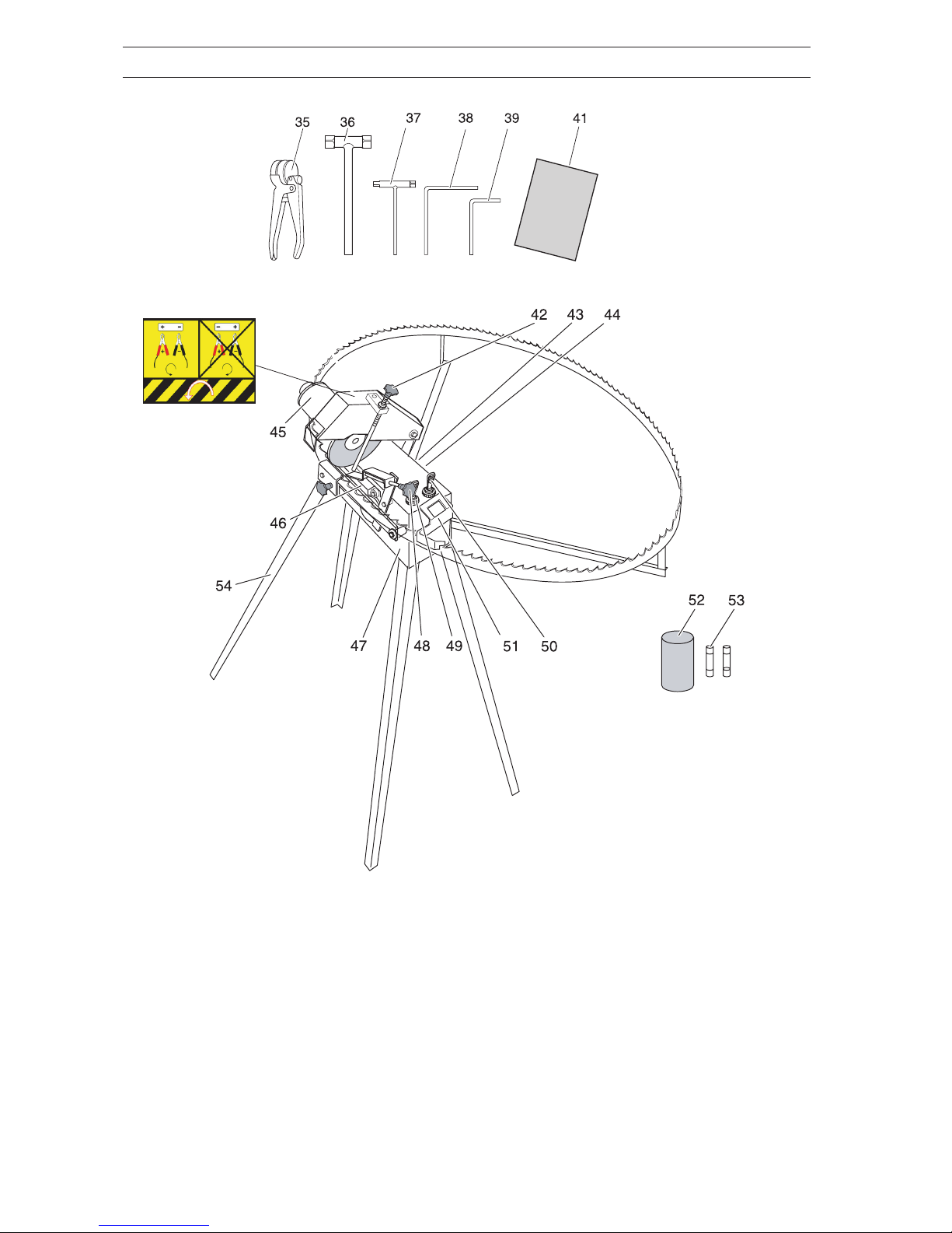
Dismantling
Dismantle the bandsaw blade as follows:
1. Remove the guards over the band wheels.
2. Loosen the right-hand band wheel by crank-
ing about 10 turns anticlockwise.
3. Carefully remove the bandsaw blade.
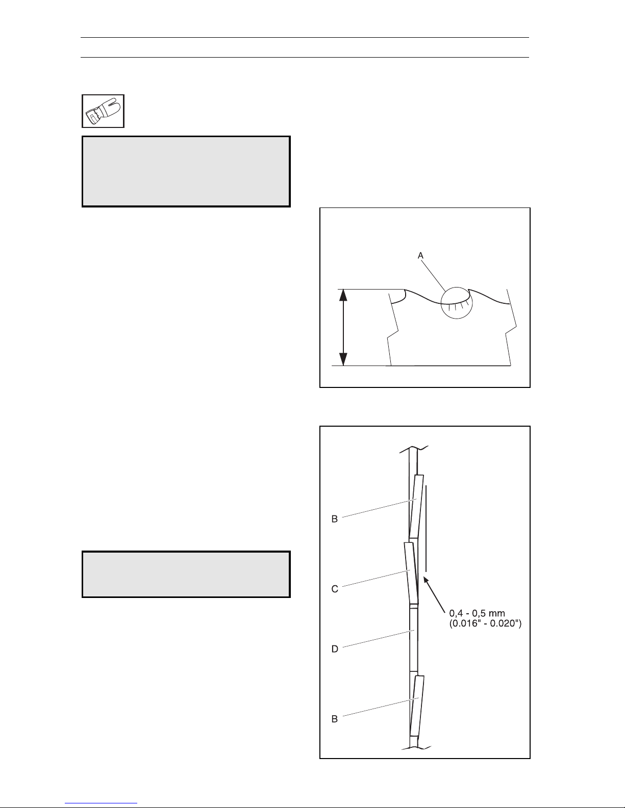
Cleaning and Inspection
Clean sawdust and any coating from the bandsaw
blade. Now check whether there are any cracks
(A) in the gullets. Small cracks can be ground
away when sharpening the bandsaw blade. If the
cracks are so large that they cannot be ground
away, the bandsaw blade should be discarded.
Cracks in the gullets are the most common cause
of bandsaw blade breakage. The bandsaw blade
can be ground to a minimum width of 24 mm. See
FIG. 76. A new bandsaw blade is 32 mm wide.
The bandsaw blade should be discarded once
any part of it reaches the minimum width.
Setting the Saw
The bandsaw blade’s teeth should be set to the
dimensions shown in the adjoining figure. Every
third tooth should remain unset. The teeth should
be set as follows:
B=Set to the right, 0.4-0.5 mm.
C=Set to the left, 0.4-0.5 mm
D=Not set.
The more accurate the set is made, the straighter
and smoother the bandsaw blade runs when
cutting the log. The bandsaw blade should be set,
at a minimum, after every third sharpening.
WARNING!
Never use a damaged bandsaw
blade.
min. 24 mm
!
!
FIG. 77
FIG. 76

English –7
Saw Setting Pliers
MAINTENANCE
For optimal results, the bandsaw blade should be
set using the saw setting pliers as described on
page5.
The saw setting pliers are adjusted to the correct
setting size.
Place the saw setting pliers over the saw tooth so
that the pliers’fixing angles rest on the two
closest teeth.
Activate the pliers and the saw tooth will be set
away from the operator.
FIG. 78

8–English
MAINTENANCE
Sharpening
WARNING!
The bandsaw blade is sharp
and can cause cuts. Warning
for personal injury. Wear
protective gloves whenever
you handle the bandsaw blade.
Hardwoods or frozen timber 7°
Medium hardwoods 10°
Softwoods 14°
After sharpening, the bandsaw blade should be
set as described in the instructions on the
previous page.
The more accurate the sharpening, the straighter
and smoother the bandsaw blade runs when
cutting the log.
Radii
The radius in the area (A) should be 1-3 mm.
A radius under 1 mm increases the risk of
cracking.
A radius over 3 mm means that the chips are not
broken.
Angles
The clearance angle should be 10-12°and the
cutting angle (F) varies depending on the spe-
cies of wood as follows:
Before sharpening, the bandsaw blade’s teeth
should be set using the saw setting pliers.
The rake angle should be 90°. See the figure to
the right.
Shape of the Tooth
As the bandsaw blade is sharpened, it is impor-
tant that the teeth and tooth valleys keep their
original shape.
For optimal results, the bandsaw blade should be
sharpened with the grinder. The procedure is
described on the following pages.
On delivery, the grinder is adjusted for the correct
angles and tooth shape.
!
FIG. 81
FIG. 79
FIG. 80
FIG. 82

English –9
Place the grinder on a table and fold out the
support arms. The central support arm can be
anchored to the table at G to give a more stable
set-up.
Connect the cables to a 12-volt power source.
The power source can be a battery or a battery
charger.
The red cable is connected to + and the black to -.
If the cables are interchanged, the grinding disc
and feed motor will run in the wrong direction.
WARNING!
Do not store petrol in the vicin-
ity of the grinder. Sparks from
the grinding disc or the electri-
cal connection can ignite.
Setting Up the Grinder
MAINTENANCE
Sharpening with the Grinder
WARNING!
The bandsaw blade is sharp
and can cause cuts. Warning
for personal injury. Wear
protective gloves whenever
you handle the bandsaw blade!
The grinder can be used on bandsaw blades with
a pitch of 16 - 32 mm. The grinding disc may
need to be redressed for other tooth profiles.
1. Loosen the knob (43) and set the correct
cutting angle (F). See FIG. 83.
2. Tighten the knob (43).
3. Check that the grinding disc has the correct
profile. See the templates at the rear of the
binder. The templates can be cut out and
placed against the grinding disc.
CAUTION! A new grinding disc must be
shaped before use. Use the supplied whet-
stone (52).
4. Fold up the grinding motor (45), hold up the
feed link (H), and insert the bandsaw blade.
The bandsaw blade should lie in the cut-outs
in the three support arms.
5. Check that the bandsaw blade rests on the
two supports (I). The support arms can be
bent if the bandsaw blade does not lie
against both the supports.
6. Adjust the bolt (J) so that the bandsaw blade
runs freely and at the same time is braced.
!
!
FIG. 85
FIG. 83
FIG. 84

10 –English
MAINTENANCE
WARNING!
Risk of the grinding disc com-
ing loose and causing personal
injury. Ensure the power supply
is connected so that the grind-
ing disc rotates in the right
direction, that is, sharpening is
performed downwards-back-
wards.
7. Start the feed with the power switch (49). The
feed cam wheel (K) should rotate anticlock-
wise. If this is not the case, the connection
cables have been interchanged.
8. Stop the feed and check where the grinding
disc goes down against the bandsaw blade.
9. Adjust the knob (L) until the grinding disc just
touches the inside of the saw tooth (M).
Points 7 and 8 above may need to be re-
peated.
10. Insert the lifter (N) in the appropriate hole in
the lever (O) and start the feed. Adjust the
knob (P) until the grinding disc just touches
the entire tooth valley while fed.
11. Stop the feed and turn both knobs 1/2 turn
anticlockwise.
CAUTION! Do not grind to heavily. This can
destroy the hardening of the teeth. Each turn
of the adjuster screws corresponds to a
grinding depth of 0.75 mm. The maximum
grinding depth per sharpening is 0.1-0.2 mm.
If the bandsaw blade is very worn, grind
several times.
WARNING!
Risk of damaging the grinding
disc or bandsaw blade, which
can result in personal injury.
The grinding disc must not be
running during the procedure
set out in points 8-11 below.
!
!
FIG. 88
FIG. 86
FIG. 87

English –11
WARNING!
Wear protective glasses while
grinding!
Fitting the Bandsaw Blade
Fit the bandsaw blade on the one-man sawmill
according to the instructions in the operator´s
manual for the one-man sawmill.
Changing the Grinding Disc
WARNING!
Before changing the grinding
disc, disconnect the power
supply to the grinder!
WARNING!
Check that the grinding disc
shows no signs of cracking and
that it is secured to the spindle.
Stop the grinding disc immedi-
ately if abnormal vibrations
occur.
MAINTENANCE
1. Fit the stop pin (Q).
2. Start the grinding disc and feed using the
power switches (49 and 50).
3. When the grinder stops automatically,
remove the stop pin.
4. Fold up the grinding motor and remove the
bandsaw blade.
1. Fold up the top section of the grinder.
2. Hold the grinding disc and loosen the nut (R)
using a pair of pliers.
3. Remove the old grinding disc and fit the new
disc. Tighten the nut (R) lightly using a pair of
pliers.
!
!
!FIG. 89
FIG. 90

12 –English
Motor Data, Grindlux 4000
Grinder motor
Voltage, V:
Speed, rpm:
Peripheral speed, m/s:
Power, W:
Amperage, A:
Grinding disc, mm:
Fuse, A:
Weight, kg:
Whetstone:
12
2800
22
90
7.5
150x6x16 (531 01 32-66)
12 / 0.25
8.24
531 01 32-63
TECHNICAL DATA
Templates for Dressing the Grinding Disc

503 23 00-31 H
531 01 32-51 G
531 01 32-54 G
531 01 32-55 G
531 01 32-58 G
531 01 32-58 G
531 01 32-60 G
531 01 32-61 G
531 01 32-62 G
531 01 32-62 G
531 01 32-63 G
531 01 32-64 G
531 01 32-64 G
531 01 32-66 G
531 01 32-68 G
531 01 32-69 G
531 01 32-70 G
531 01 32-73 G
531 01 32-74 G
531 01 32-74 G
531 01 32-75 G
531 01 32-76 G
531 01 32-76 G
531 01 32-77 G
531 01 32-78 G
531 01 32-79 G
531 01 32-80 G
531 01 32-81 G
531 01 32-82 G
531 01 32-84 H
531 01 32-85 H
531 01 32-86 H
531 01 32-87 H
531 01 32-88 H
531 01 32-89 H
531 01 94-86 G
725 23 68-51 H
731 23 14-01 H
732 21 14-01 H
PART NUMBER SQUARE NOTE PART NUMBER SQUARE NOTE PART NUMBER SQUARE NOTE PART NUMBER SQUARE NOTE

´+H+@¶6^¨
compl 531 01 94-86
531 01 32-68
531 01 32-70
531 01 32-64
531 01 32-64
531 01 32-77
531 01 32-76
531 01 32-78
531 01 32-66
531 01 32-63
531 01 32-55
531 01 32-69
531 01 32-76
531 01 32-79
**531 01 32-81
**531 01 32-82
**compl 531 01 32-80
****compl 531 01 32-51 *compl 531 01 32-60
***
***compl 531 01 32-54
***531 01 32-61
531 01 32-62
531 01 32-62
531 01 32-58
531 01 32-58
*
*531 01 32-74 ****
*
****
****
****
****
****
****
531 01 32-75 (x2)
**531 01 32-73
531 01 32-74
G

compl 531 01 32-84
531 01 32-87 (x14)
503 23 00-31 (x16)
725 23 68-51 (x3)
731 23 14-01 (x8)
732 21 14-01 (x2)
531 01 32-88 (x4)
531 01 32-89
531 01 32-85
531 01 32-86
H

2002W24
´+H+@¶6^¨
114 01 13-26
Table of contents