1110
OPERATIONOPERATION
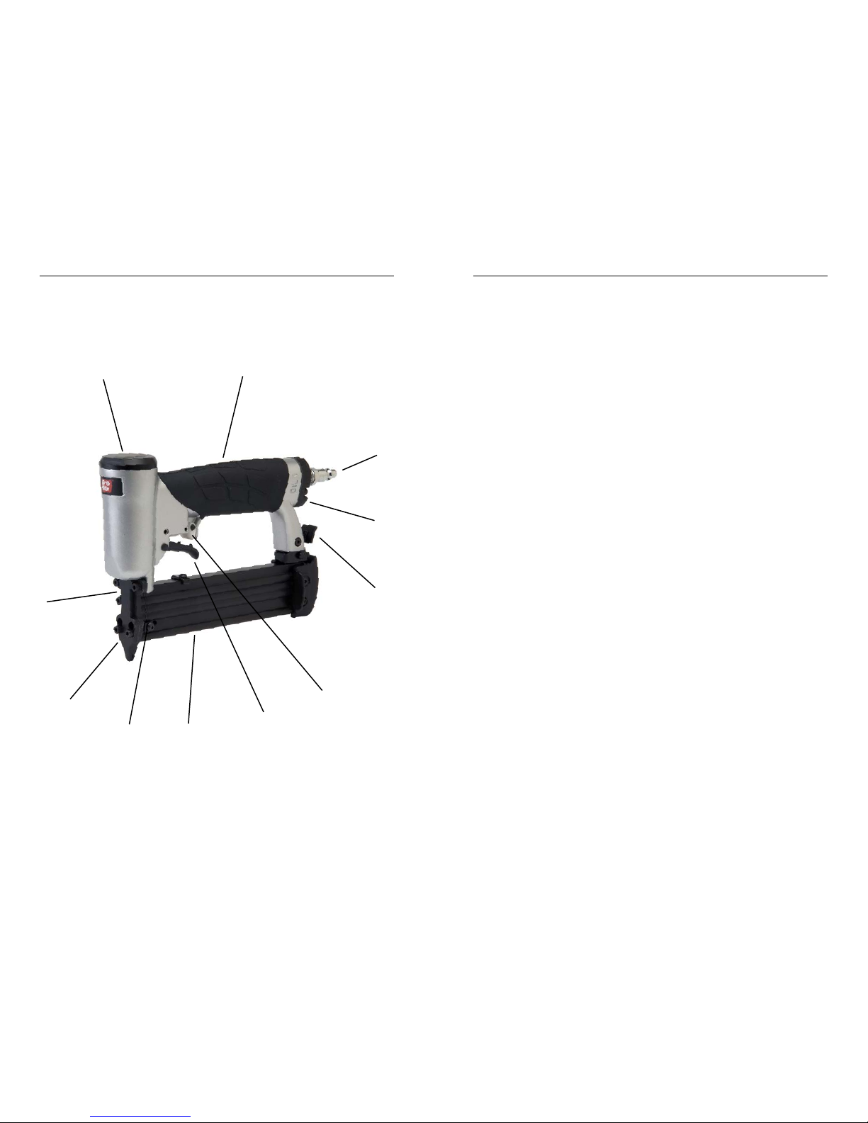
LOADING FASTENERS
LOADING INSTRUCTIONS
A fastener can be driven unintentionally if the trigger is depressed while
the safety lever is in the operating position . Always disconnect tool
from air supply before loading fasteners, making adjustments, or per-
forming any service on tool. Always keep safety lever in “safe” position
and finger off trigger until ready to drive a fastener.
DANGER
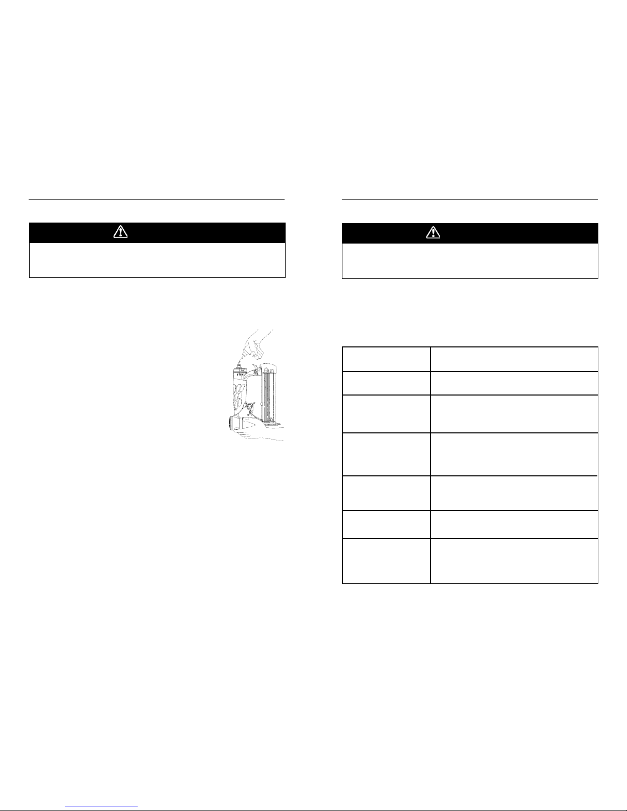
1. Disconnect tool from air supply
using quick-connect coupling.
2. Depress magazine latch (A),
and pull magazine cover (B)
back until cover is fully open.
3. Insert fastener strips (C),
placing points down. Fastener
points must be placed into
track at bottom of magazine for
proper feeding and driving.
4. Slide magazine cover closed.
Magazine must click into
latched position.
5. Move trigger safety lever (D)
forward to “safe” position to
prevent trigger from actuating
tool when depressed.
6. Tool is now loaded and ready
to be connected to an air
supply for operation.
CLEARING JAMS
1. Disconnect tool from air supply
using quick-connect coupling.
2. Move trigger safety lever (D)
forward to “safe” position to
prevent trigger from actuating
tool when depressed.
3. Depress magazine latch, and
pull magazine cover back until
cover is fully open.
4. Remove fastener strips.
5. Loosen nose door plate (F)
mounting screws, and slide
nose plate down and off nose.
6. Remove jammed fastener.
7. Replace nose plate, and secure
with screws.
8. Reload fasteners, and close
magazine cover.
9. Tool is now loaded and ready to
be connected to air supply.
3. Place nose of tool against
workpiece, positioning nose for
desired fastener driving posi-
tion.
4. Depress trigger to drive a
fastener, and release trigger.
Lift tool from workpiece.
5. Repeat steps 3 & 4 for each
fastener to be driven. Adjust air
pressure as needed to provide
consistent fastener drive.
Check reload indicator window
(E) periodically to make sure
tool doesn’t run out of fasten-
ers.
6. Move trigger safety lever (D)
forward to “safe” position after
desired fasteners have been
driven, or before reloading.
7. Disconnect tool from air supply
when done fastening.
TOOL OPERATION
1. Connect tool to air supply
using quick-connect coupling.
2. Position tool over work surface,
and move trigger safety lever
(D) backward to permit trigger
to actuate tool when de-
pressed.
A
CB
D
D
E
D
F