Impacts STREAMER S320RD User manual

Operating Manual
S320RD
Your Partner for Mobile Surface Preparation
IMPACTSAmericas.com

IMPACTS Americas
1384 Bungalow Rd.
Morris, IL 60450 USA
(815) 941-4800
(815) 941-4600 Fax
www.IMPACTSAmericas.com
[June 2016]

Operating Manual S320RD
1
Table of Contents
1.0 Technical Data.............................................2
2.0 Safety Instructions .........................................4
3.0 General Information . . . . . . . . . . . . . . . . . . . . . . . . . . . . . . . . . . . . . . . 10
4.0 Transportation............................................20
5.0 Start Up .................................................22
6.0 Operation................................................28
7.0 Maintenance - S320RD .....................................34
8.0 Electrical Systems ........................................50
9.0 Error Diagnostics .........................................54
For spare parts, please refer to a separate
publication called "S320RD Parts Catalog."
Please note: The following safety instructions must be followed as
shown in this operating manual. Failure to do so may result in hazard
to health or possible death.

S320RD Operating Manual
2
Chapter 1.0 Technical Data
1.1 Rating
1.2 Unit Specifications
1.3 Operative Range and Correct Usage
1.4 Advice for L.P. (Propane) Gas Mode
1.5 Advice for Operators of the Blast Machine
1.6 Machine Type Designation
1.1 Rating
Machine: IMPACTS Blast Machine
Machine-Type: S320RD
Manufacturer: IMPACTS Americas
1384 Bungalow Rd.
Morris, IL 60450 U.S.A.
1.2 Unit Specifications
Machine S320RD
Length 81 in. / 2060 mm
Width 34 in. / 864 mm
Height 60 in. / 1520 mm
Weight 1,808 lb. / 820 kg
Engine Kawasaki:
Model FD750D
Engine Type Liquid-cooled, 4-cycle
Number of Cylinders 2
Displacement 745 cm3
Max. Power 17.7 kW (23.7 HP) / 3600 min-1
Consumables:
Capacity (I) Type
Engine Oil 2.0 SAE 10W40 SF, SG, SH or SJ Semi synthetical
Coolant 2.7 e.g. Antifreeze X12 Plus Mixed ratio: 50%
Hydraulic Oil 20 HLP46
Compressor Oil 0.5 API CC/SC SAE40
Gear Box Oil 0.36 e.g. Shell Omala S2 G 150

Operating Manual S320RD
3
1.3 Operative Range and Correct Usage
The blast machine is designed to be used on clean, dry, horizontal surfaces without any
obstacles. The machine cannot be used for any other purpose. The manufacturer will
not be held liable for damages resulting from incorrect usage. In cases of wrong usage,
the user will assume all risks and damages.
1.4 Advice for L.P. (Propane) Gas Mode
Settings or repairs of the L.P. Gas system must only be performed by a specialist. If
there is any gas smell or leak, the Blastmachine must be taken out of operation at once
and the tank shut-off valve must be closed. The Blastmachine must only be taken in
operation again after the cause has been found and removed by a specialist.
L.P. Gas system components, specifically gas lines, must not come into contact with
sharp-edged, hot or rotating parts. Lines must not be bent. The Blastmachine must be
inspected every day, specifically for tightness and tight seat of the gas components.
1.5 Advice for Operators of the Blast Machine
During the operation of the machine, it may be possible to exceed the acceptable noise
levels of 85 dB(A). This is dependent on various locations and circumstances. When the
noise level is 85 dB(A) or more, the machine operator and the persons working near the
machine must wear sound-insulating devices.
1.6 Machine Type Designation
Machine Type: S320RD
Unit / Designation: IMPACTS Blast Machine
Working Width: 12.6 in. | 320 mm
Drive: Progressively adjustable 1-98 ft/min | 0-30 m/min
Blasting Capacity: Up to 2,153 SF/hr | 200 m²/h
Abrasive Consumption: 100-200 g/m²

S320RD Operating Manual
4
Chapter 2.0 Safety Instructions
2.1 Explanation of Warnings and Symbols
2.2 Organizational Measures
2.3 Personnel Selection and Qualification
2.4 Safety Precautions Applicable to Different Operating Conditions
2.5 Repair Work, Maintenance Activities, and Default Repair on the Job Site
2.6 Definition of the Safety Off Position
2.7 Dangerous Aspects of the Machine
2.8 Electrical Engineering Regulations
2.9 L.P. Gas Engineering Regulations
2.10 For Special Attention
2.1 Explanation of Warnings and Symbols
The following symbols are used in the operating instructions to highlight areas
of particular importance:
Operational Safety
This symbol will be shown in these Operating Instructions next to all safety precautions
that are to be taken in order to ensure prevention of injury. Follow these instructions and
take special care in these circumstances. In addition to these instructions, the general
safety precautions and the local accident prevention guidelines also should be followed.
Please check if there are special regulations for the particular job site.
Safety Goggles/ Ear Protection
Information, instructions, and restrictions with regards to possible risks of personal injury
or extensive damage to materials.
Electrical Warning
Warning against dangerous voltages.
Propane Gas Warning
Warning against dangerous aspects of the propane gas system.
2.2 Organizational Measures
Operating Instructions are to be kept near the machine and be attainable all the time.
In addition to the Operating Instructions, general and legal regulations regarding accident
prevention and environmental protection must be indicated every time.
Such duties may, for example, relate to the handling of hazardous substances or to the provision
and wearing of personal protection equipment as well as compliance with local traffic regulations.

Operating Manual S320RD
5
The Operating Instructions must be supplemented by instructions including the duty to supervise
and report relating to particular local working practices; for example, work organization, work
procedures, and personnel allocation.
Personnel working with the machine must read the Operating Instructions before starting the work,
in particular. Chapter 2 "Safety Instructions." This must be done before starting any work with the
machine. This applies to certain activities such as setting up the machine, carrying out maintenance
work, or training staff to work with the machine.
From time to time, the working practices of the staff should be checked regarding awareness of
safety and hazards.
Personnel must tie back long hair and not wear loose clothing or any jewelry. There is
risk of injury in getting stuck or being drawn into moving machinery. Use personal
protection equipment whenever necessary and required by regulations!
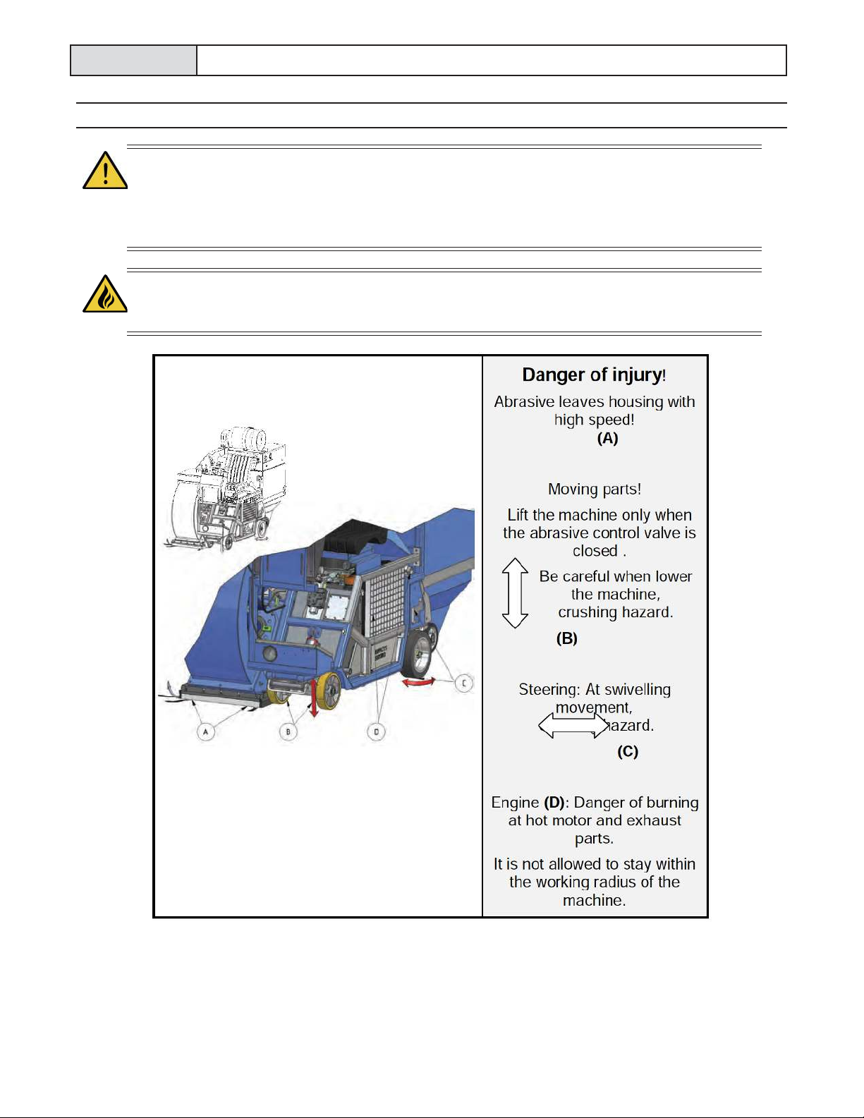
Take notice of all safety and hazard signs on the machine. They must be kept complete and legible.
If safety-critical changes occur to the machine or its performance, the machine must be
shut down immediately! The cause of the fault must be determined immediately and be
repaired before starting work again.
Changes, add-ons, or conversions which might have an influence to the safety of the machine
must not be undertaken without the permission of the manufacturer. This applies in particular to the
fitting and adjustment of safety devices and to welding on major and load bearing parts.
Spare parts must always comply with the technical requirements and the specification of the
manufacturer. Original spare parts by the manufacturer are guaranteed compliant.
Inspection intervals and intervals for recurring checks specified in these Operating Instructions
must be followed. At the same time, it is necessary to meet all legal requirements. To perform
maintenance work correctly, it is important to be equipped with proper tools for the task in question.
The location and the operation of fire extinguishers must be made known at each job site. Take
note of the facilities for fire reporting and fighting fires!
2.3 Personnel Selection and Qualification
Fundamental Duties
Only trained personnel can operate and perform work on the machine. Note the
statutory minimum age! Clearly specify the responsibilities of personnel for operation,
setup, service, and maintenance work.
Clearly define the machine operator's responsibilities regarding traffic safety regulations and
empower him/her to decline instructions from third parties who are not complying with the safety
requirements.
Personnel being trained or individuals testing the equipment must always be supervised by an
experienced operator.

S320RD Operating Manual
6
Work on the electrical parts of the equipment may only be undertaken by a skilled
electrician or by a trained person under the guidance and supervision of a skilled
electrician in accordance with the electrical engineering regulations.
Work on the L.P. Gas system may only be undertaken by a specialist, as well as in
accordance with the L.P. Gas system regulations for L.P. Gas driven vehicles.
2.4 Safety Precautions Applicable to Different Operating Conditions
Avoid any method of working that impairs safety! All precautions have to be taken. The machine
must only be used in a safe and functional condition.
Only operate the machine when all safety devices and related safety equipment, e.g.
detachable safety devices, emergency stops, and suction devices, are present and
operational!
The machine has to be checked visually at least once a day for any damage and defects.
In the event of operational malfunctions the machine must be shut down immediately and secured.
The error must be rectified before starting the machine again.
Secure the work area around the machine in public areas providing a safety distance of
at least 7 ft./ 2m around the machine.
Default must be rectified immediately!
Start up / switch off operations and control devices have to be handled in accordance with the
Operating Instructions.
All persons in the proximity of the machine must wear safety glasses with lateral
protection as well as safety shoes. Ear protection may be required. The operator is
required to wear close fitting protective clothing.
Use only extension cables for extending the main cable that are sized and marked in accordance
with the overall power consumption of the machine following valid VDE and local guidelines.
Before starting the machine ensure that no person in the job site can be endangered when the
machine starts running.
Do not switch off or remove the exhaust and ventilation devices when the machine is
running!
2.5 Repair Work, Maintenance Activities, and Default Repair on the Job Site
Mechanical Service Work
These activities can only be undertaken by qualified personnel. Please follow any special
safety instructions in the various chapters on servicing the machine (see Chapter 7).

Operating Manual S320RD
7
Before starting any servicing work on the machine, put the machine in the Safety off position (as
described in Chapter 2) in order to prevent the machine from being switched on accidentally.
Adjustments, servicing, and inspection work and inspection intervals specified in these Operating
Instructions as well as any information on the replacement on parts and systems of the machine
must be undertaken and/or complied with.
The operator must be informed of any maintenance or repair work done to the machine.
Startup and shut off procedures must be done in accordance with the Operating Instructions during
all work related to the use, repair, and adjustment of the machine. The repair personnel must also
be aware of the safety devices during inspection, maintenance, and repair.
The machine must be shut off completely for repair or maintenance work. Please remove
the ignition key from ignition/starter-switch in order to prevent the machine from being
switched on accidentally.
The integrated dust collector bin must be emptied before transportation. Please handle in
accordance with the regulation how to dispose the dust and make sure that you meet the local
regulations. Do not use any aggressive cleaning materials! Use only lint-free cleaning cloths.
Always remember to tighten any screw connections that are undone during servicing and
maintenance work!
If safety devices need to be dismantled during setting up, servicing, or repair work, these safety
devices must be reinstalled and inspected immediately after completion of the service.
Make sure that process materials and replacement parts are disposed of safely and in an
environmentally-friendly manner.
Welding operations: To prevent any damage to electric or electronic components,
disconnect the battery and alternator before any welding operations are undertaken.
Make sure that electrical components used for replacement purpose comply with the original parts
and are correctly adjusted if necessary.
2.6 Definition of the Safety Off Position
The safety off position is the position of the machine when it cannot generate any hazard. Setting
the machine in the safety off position means:
1. Switch off the blast machine.
2. Wait for standstill of all drives.
3. Remove the ignition key.
4. Close the shut-off valve of the fuel or L.P. Gas system.
5. Secure the machine against accidental start up.

S320RD Operating Manual
8
2.7 Dangerous Aspects of the Machine
Every machine not used according to the regulations may be hazardous for personnel
during operating, setting-up, and service. The operating authority is responsible for
compliance with the safety regulations during operation and maintenance of safety
devices supplied with the machine as well as the provision of appropriate additional
safety devices.
Exhaust emissions: Only operate the machine in well ventilated areas. Operating the
machine in confined areas may lead to build up of harmful exhaust emissions, which
may cause dizziness, drowsiness or even death!

Operating Manual S320RD
9
2.8 Electrical Engineering Regulations
Work on the electrical parts of the equipment may only be undertaken by a skilled
electrician or by a trained person under the guidance and supervision of a skilled
electrician in accordance with the electrical engineering regulations.
Use only extension cables for extending the main cable that are sized and marked in
accordance with the overall power consumption of the machine following valid VDE and
local guidelines. In case there is any question, ask the manufacturer or a skilled
electrician.
Only start work once you are familiar with the electrical engineering regulations that apply to your
area.
Only use voltage seekers that comply with the regulations when troubleshooting. From time to
time, check voltage seekers to ensure that they are operationally efficient.
2.9 L.P. Gas Engineering Regulations
Regarding setup and operation, vehicles with a liquid gas combustion motor are subject to the
"common provisions" as well as the "special provisions" according to § 29 UVV "Use of liquid gas"
(BGV D34).
Inspection of vehicles with liquid gas combustion motor by the expert according to §§ 33 and 37
UVV "Use of liquid gas" (BGV D34).
2.10 For Special Attention
Use only proper and default free tools for your work. Damaged tools have to be repaired immediately
or be replaced.
Use safety equipment and clothing (e.g. safety glasses, safety shoes, safety gloves) during
operation of the machine at all times for your safety.
Please instruct your operators and the repair personnel about the following
points:
• Greasing, cleaning, and all repair work is only allowed if the machine is in the safety off position
(see Section 2.6).
• No one is allowed to open or remove safety covers while the machine is running.
• Replace all safety covers and safety devices after cleaning, repair, and maintenance work.
• Do not touch moving parts or walk into the working path of the machine.
• Before start up of the machine after any cleaning, repair, or maintenance work, ensure that no
person in the working area could be endangered by the machine.

S320RD Operating Manual
10
Chapter 3.0 General Information
3.1 Operative Range
3.2 Scope of Supply
3.3 Description of the Machine
3.4 Operating Elements
3.5 The Wheel Kit
3.6 The Separator
3.7 The Traction Drive
3.8 The Base Seals
3.9 The Filter Housing
3.10 The Dust Bin and Lifting System
3.11 The Fan
3.12 The Automatic Cleaning System
3.13 Abrasive Media
3.14 Selecting Abrasive Media
3.15 Care and Maintenance
3.1 Operative Range
The IMPACTS blast-cleaning machine S320RD is a downward blasting machine with a closed
abrasive circuit designed for the pre-treatment of horizontal surfaces. The bouncing impact of
metallic abrasive onto the surface thoroughly removes surface contaminants, coats of paint,
sealants, and thin coatings.
A suitable filter unit is integrated into the machine in order to separate the dust from the abrasive.
A specially designed dust collection system ensures dust-free operation of the machine and clean
air at the workspace.
3.2 Scope of Supply
• Blast Machine (S320RD)
• Manual (1)
• Maintenance Box (optional)
• Magnetic Broom (optional)

Operating Manual S320RD
11
3.3 Description of the Machine
1 Abrasive Feeding
2 Side Force Wheel Housing
3 Rebound
4 Separator
5 Controls
6 Base Seal
7 Height Adjustment / Lifting Cylinder
8 Motor
9 Traction Drive / Steering
10 Hydraulic Components
11 LPG System
12 Filterhousing
13 Dust Bin
14 Lifting System Dust Bin
15 Fan
16 Automatic Cleaning System
The blast wheel method is a revolutionary invention based on a simple principle:
After mechanical pre-acceleration, the abrasive is thrown onto the surface at high speed by the
blast wheel. Once the abrasive has impacted the surface it rebounds into a rebound plenum. The
rebound plenum deflects the abrasive into an air current separator. In this location, dust and other
contaminants are removed from the abrasive so that only abrasive containing a very small amount
of dust is falling back into the abrasive storage hopper to reflow to the blast wheel.
The integrated filter unit provides a dust free working environment, and improved service life
of machine and tools. Ensuring a clean environment is a matter of ethics and should be observed
by professional associates. IMPACTS uses a particularly arranged filtering material that is certified
and has high filtration efficiency.

S320RD Operating Manual
12
3.4 Operating Elements
The Control Panel contains all controls and instruments used for supervision and control of the
machine.
1 Control lever lift / lower
2 Steering wheel
3 Hour meter
4 Ignition / starter switch
5 Charge current warning light
6 Overheat warning light
7 Switch light
8 Combustible selection switch
9 Combined display
10 Control lever abrasive valve
11 Control lever traction drive
12 Revolution counter
13 Choke fuel mode
14 Accelerator cable
15 Oil level and temperature indicator
16 Differential pressure gauge
17 Pressure gauge
Control Lever Lift / Lower
Lift machine: Pull lever (1) back. Lower machine: Push lever (1) forward.
Steering Wheel
Steering wheel (2) steers machine in required direction.
Hour Meter
The hour counter (3) shows the sum of the actual working hours performed by the blast wheel.
Ignition / Starter Switch
Connects and disconnects the power supply. Starts and stop engine. When the ignition key (4a) is
removed, the Blastmachine is protected from use by unauthorized persons.
Charge Current Warning Light
When lit (5) indicates that the battery is not charged.
Overheat Warning Light
When lit (6) indicates that the coolant temperature is too high.

Operating Manual S320RD
13
Switch Light
To switch on the front working lamp. In position On the switch (7) is illuminated.
Combustible Selection Switch
Combustible selection switch (8): Fuel or L.P. Gas mode: In fuel mode
remove plug from air filter housing.
Combined display with engine oil pressure warning light
Combined display (9) shows the engine speed and travel speed. Engine oil
pressure warning light (9a), when lit indicates insufficient oil pressure in the
engine. (Shown travel speed divided by 10 is the travel speed in m/min).
Control Lever Abrasive Valve
This Lever (10) regulates the magnetic valve to control the flow of abrasive towards the blast wheel.
Open valve: Pull lever back.
Close valve: Push lever forward.
Control Lever Traction Drive
Control lever (11) to control drive direction and speed.
Push lever forward: Machine drives forward, speed depending on lever position.
Pull lever back: Machine drives backward, speed depending on lever position.
Revolution Counter
Revolution counter (12) shows the engine speed.
Choke Fuel Mode
Pull lever (13) back to open the choke valve when engine is cold. For further information look at the
owner's manual of the Kawasaki engine.
Accelerator Cable
Accelerator cable (14) to control the engine speed. Mode of motion: Micro
adjustment by rotating the nut (14b); press the button (14a) to make big push/
pull adjustment.
Oil level and temperature indicator
Indicator (15) which shows the hydraulic oil level and temperature.
Differential Pressure Gauge
The differential pressure gauge (16) shows the current conditions of the filter cartridges.
Pressure Gauge
The pressure gauge (17) shows the working pressure of the automatic cleaning system.

S320RD Operating Manual
14
3.5 The Wheel Kit
The heart of every blast-machine is
the blast wheel (1) this will throw the
abrasive to the surface to treat, using
centrifugal forces. The blast wheel is
placed in a side force wheel housing
(2) protected with replaceable wear
plates (3).
The blast wheel is driven by a belt
drive and mounted on a bearing
unit (4). The correct rotation of the
S320RD blast wheel is CCW. (L)
The center of the blast wheel shows
a pre-accelerator, called impellor, (5)
feeding dosed quantities of abrasive
onto the blades of the turning blast wheel. On top of this is the control cage (2) which, once it is
carefully set, regulates the direction of the abrasive flow.
The Control Cage, held by two clamps needs to be adjusted (V) so the blast pattern shows to the
center of the machine. Turning the control cage CCW will move the Blast Pattern to the right and
turning it CW will move the blast pattern to the left.
3.6 The Separator
1 Separator housing
2 Deflector
3 Separator tray
4 Separator lid with baffle plate
5 Magnetic control valve
6 Feed spout
7 Abrasive control cable
8 Lever
9 Control lever magnetic-valve
The separator (1) is mounted to the end of the
rebound plenum. The deflector (2) and baffle plate
(4a) will stop the reflected abrasive.
The filter, connected to the hose connector (1b) will
generate an appropriate airflow within the separator
so this device will separate dust from abrasive. The
abrasive drops back to the storage where it has to
pass a wire mesh tray (3).

Operating Manual S320RD
15
This tray (3) is fitted to prevent any coarse contaminants from getting into the blast wheel. In order
to clean the wire mesh tray it can be removed from the side.
To regulate the flow of abrasive to the blast-wheel there is a magnetic-valve (5) fitted between
Storage-Hopper (1a) and feed spout (6).
This valve has a turnable shutter (5a) that is linked to a lever (8) controlled by the control cable (7).
Changing the angle of the shutter position results in a different amount of abrasive flowing to the
blast wheel. Feeding more abrasive causes more work and results in a higher load on the engine.
Load on the engine is indicated by the revolution counter.
Do not load more abrasive than recommended for the S320RD. The engine speed should be
between 3,250 and 3,300 min-1.
3.7 The Traction Drive
1 Hydraulic Drive Motor
2 Drive Wheel
3 Bypass Valve
The machine S320RD is driven by two hydraulic drive
motors (1). The drive wheels (2) are permanently
connected to the hydraulic drive motors.
To move the machine by hand, change the position of
the bypass valve (3). Once the machine is in place, be
sure to change back the position of the bypass-valve to
avoid inadvertent movements of the machine.
3.8 The Base Seals
1 Magnetic Seal
2 Brush Seal
3 Tail Seal
4 Adjuster Screw
5 Magnet Holder
6 Seal Plate
On the front and side are magnetic seals (1)
surrounded by brush seals (2). On the rear
you will find a seal called tail-seal (3). This
seal slides over the surface and prevents
abrasive getting out of the blast area.
All seals should seal against abrasive spray. The correct setting of the magnets is approx. 12mm
over the floor depending on the application. This setting is very important for best function of the
machine. The adjustment is done by setting screws. See chapter 5 for adjustment instructions.

S320RD Operating Manual
16
3.9 The Filter Housing
The filter housing (1) contains the filter
cartridges (2) as well as the automatic
cleaning system (10).
The cartridges separate the dust from the
air reducing the air becoming dirty.
For cleaning, there is an automatic
cleaning system which is supplied with
compressed air by a compressor.
3.10 The Dust Bin and Lifting System
Below the filter housing, the dust bin (3)
collects the dust. The dust bin collects
about 100 liters of dust and is supplied
with two wheels and one caster for easy
transport.
The dust bin (3) is fixed to the filter housing
(1) by a lifting system (5) which can be
operated by a movable lever (4).
For changing the position of the dust bin
handle (7,) loose the locking levers (6)
,move the handles to the desired position
,and retighten the locking levers.
3.11 The Fan
The fan unit (8) which is directly connected
to the filter housing, generates the required
vacuum.
To adjust the airflow, use the lever (9) which
controls the throttle valve in the top of the
air exhaust duct.

Operating Manual S320RD
17
3.12 The Automatic Cleaning System
The filter unit is equipped with an automatic cleaning system which cleans the cartridges during
operation of the filter unit. Traditional systems do not allow this. This system mainly consists of 3
components: the compressor, the air splitter, and the electronic timing control. The pressure gauge
and the differential pressure gauge integrated in the filter housing inform about the status of the
cleaning system.
3.13 Abrasive Media
In order to operate IMPACTS blast-machine S320RD
you need hardened, spherical abrasive. The machine
S320RD has been especially designed to be operated
with IMPACTS abrasive.
The IMPACTS abrasive is of very high quality and
owns the rebounding ability required for the efficient
use of model S320RD. The selection of the abrasive
is very important since this is the material to carry out
the surface treatment.
Take off the lid (2) from the separator (1), assure the
wire mesh tray (4) is in place, and fill up abrasive
(3) distributing evenly up to the bottom of the mesh.
Occasionally check function of the deflector shutter.
3.14 Selecting Abrasive Media
Media IMPACTOR S 290
Applications:
• Creates fine profiles and is often used when the surface is only subsequently sealed, for
example, on vacuumed concrete or for the removal of thin layers of paint on non-glazed tiles
Media IMPACTOR S 330
Applications:
• Creates a fine to medium texture on concrete
• Removes glazing from tiles prior to subsequently coating with anti-skid floor sealing
• Removes old impregnations and coatings about 1 mm thick
Media IMPACTOR S 390
Applications:
Standard abrasive, suitable for about 50-60% of all applications. Creates a medium profile on
concrete. Fulfills the same purpose as Media No. 3 when a higher speed of the machine is required,
i.e. on asphalt, in order to keep the thermal load low.

S320RD Operating Manual
18
• Removes laitance from new concrete
• Roughening of smooth concrete or natural stone
• Removes coatings with a thickness of 1-3 mm
• Cleaning of steel surfaces
Media IMPACTOR S 460
Applications:
Used to generate a rough profile and to improve work output
• Removes laitance from new concrete
• Removes thicker paints or rust from steel surfaces
• Removes flex coatings from parking decks
• Removes painted road lines
• Re-texturing on asphalt surface and concrete roads
Media IMPACTOR GL18
Applications:
Use only in addition to Media No. 3 and No. 4 with maximum 30% content. This media should never
be used without blending, otherwise the wear in the machine would increase disproportionately.
• Removes polyurethane coatings
• Removes adhesive remnants
• Removes rubber deposits
• Penetrates hard to remove coatings
• Also suitable for use on steel
The effectiveness of the S320RD is dependent on the rebound effect which ensures that the
abrasive can be re-used.
Please take into account that the use of incorrect abrasive increases wear. Our service
engineers have the experience to select the appropriate abrasive for the individual
cases of application.
Please consult your IMPACTS customer service department if you have any questions about the
selection of the best abrasive for your blast cleaning work.
Table of contents
Other Impacts Shot Blasting Machine manuals