Guyson 2 Installation and operation manual

Operation &
Maintenance
Manual
Issue:
10
A6ML0066 –Euroblast SF Instruction Manual
Date:
05/2019
Page: 2
Table of contents
1. Introduction .........................................................................................................................................4
1.1 Safety recommendations..............................................................................................................4
1.2 Electrical specification ..................................................................................................................4
1.3 Blast media...................................................................................................................................5
2. Data sheets.........................................................................................................................................7
2.1 Blast cabinets................................................................................................................................7
2.2 Cyclones.......................................................................................................................................8
2.3 Dust collectors ..............................................................................................................................8
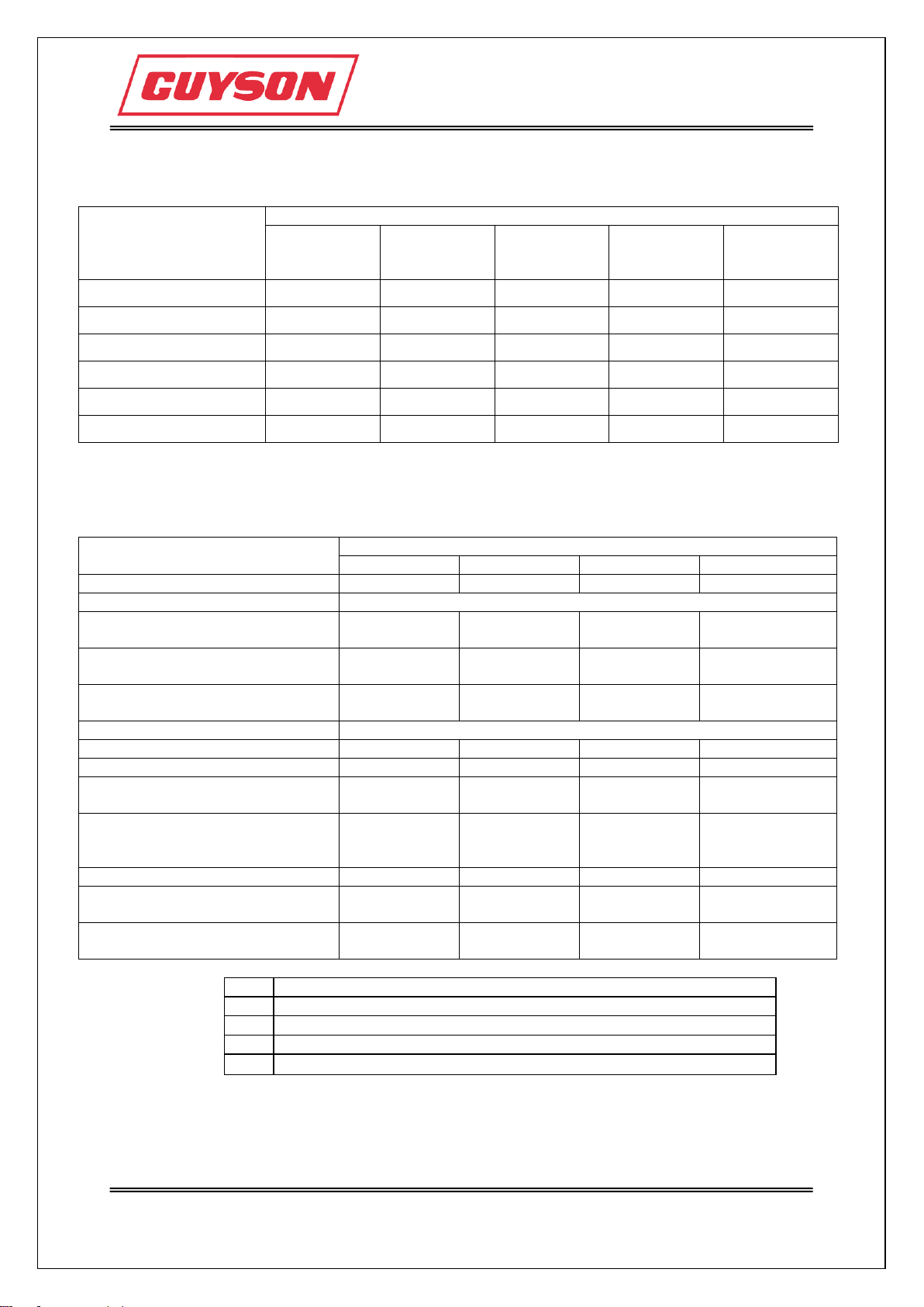
2.4 Air consumption tables .................................................................................................................9
2.4.1 Air flow measured in m³/hr at different pressures measured in bar.......................................9
2.4.2 Air flow measured in CFM at different pressures measured in psi........................................9
3. Installation.........................................................................................................................................10
3.1 Location ......................................................................................................................................10
3.2 Assembly ....................................................................................................................................10
3.2.1 Compressed air connections ...............................................................................................13
3.2.2 Electrical connections ..........................................................................................................15
4. Testing installation ............................................................................................................................16
4.1 Testing installation procedure.....................................................................................................16
4.2 Media levels................................................................................................................................19
4.2.1 Adding media to hopper.......................................................................................................19
4.2.2 Adding media to 75/16 cyclone............................................................................................19
4.2.3 Adding media to CY600 cyclone..........................................................................................20
5. Machine settings ...............................................................................................................................21
5.1 Blast settings...............................................................................................................................21
5.1.1 Blasting pressure .................................................................................................................21
5.1.2 Media pick-up tubes.............................................................................................................22
5.1.3 Stand-off distance ................................................................................................................23
5.1.4 Angle of blasting...................................................................................................................23
5.2 Extraction settings ......................................................................................................................23
5.2.1 Dust collector .......................................................................................................................23
5.2.2 Cyclone ................................................................................................................................25
6. Operation ..........................................................................................................................................27
6.1 Operating procedure...................................................................................................................27
7. Maintenance......................................................................................................................................28
7.1 Daily............................................................................................................................................29
7.1.1 Breather pads.......................................................................................................................30
7.1.2 Viewing and illumination window .........................................................................................31
7.1.3 Hoses...................................................................................................................................32
7.1.4 Pick up tubes and mixer box................................................................................................33
7.1.5 Blast nozzles........................................................................................................................34
7.1.6 Door seals............................................................................................................................37
7.1.7 Overspray.............................................................................................................................37
7.1.8 Empty waste bin...................................................................................................................38
7.1.9 Topping up media ................................................................................................................39
7.1.10 Filter cleaning.....................................................................................................................39
7.1.10.1 Replacing the filter sleeves on a 41............................................................................41
7.1.10.2 Replacing the filter cartridge on a C400......................................................................42
7.1.10.3 Replacing the filter cartridge on a C600......................................................................43
7.1.10.4 Replacing the filter cartridges on a C800....................................................................44
7.1.10.5 Replacing the HEPA14 Filter Cartridge, C600 Dust Collector....................................45
7.1.10.6 Replacing the HEPA14 Filter Cartridge, C800 Dust Collector....................................46
7.1.10.7 Bin Balance Breather Sock.........................................................................................47
7.1.10.8 Autopulse, C400 and C600.........................................................................................48

Operation &
Maintenance
Manual
Issue:
10
A6ML0066 –Euroblast SF Instruction Manual
Date:
05/2019
Page: 3
7.1.11 Compressed air filter..........................................................................................................50
7.1.12 Earthing bonds...................................................................................................................50
7.2 Weekly........................................................................................................................................51
7.2.1 Hopper elbow.......................................................................................................................52
7.2.1.1 Replacing the wear plate ..............................................................................................52
7.2.2 Cyclone ................................................................................................................................53
7.2.2.1 Replacing the wear plate ..............................................................................................53
7.2.3 Sleeves/Gauntlets................................................................................................................53
7.2.5 Turntable rotation.................................................................................................................55
7.3 Monthly .......................................................................................................................................56
7.3.1 Emptying media ...................................................................................................................56
7.4 Quarterly.....................................................................................................................................57
7.4.1 Blast gates ...........................................................................................................................57
8. FAQ’s ................................................................................................................................................58
9. Spares and servicing.........................................................................................................................60
9.1 Spare parts identification............................................................................................................61
10. Appendices .....................................................................................................................................62
10.1 Mechanical drawings and parts lists.........................................................................................63
10.1.1 Air assembly for Euroblast 2 SF & 4 SF ............................................................................63
10.1.2 Air assembly for Euroblast 6 SF, 7 SF, 8 SF, 6 SF SL, 7 SF SL & 8 SF SL .....................65
10.1.3 Air assembly for Euroblast 9 SF, 10 SF, 9 SF SL & 10 SF SL ..........................................67
10.2 Electrical schematics and parts lists.........................................................................................69
10.2.1 Electrical installation of dust collectors and cyclones ........................................................70
10.3 Proprietary manuals..................................................................................................................72

Operation &
Maintenance
Manual
Issue:
10
A6ML0066 –Euroblast SF Instruction Manual
Date:
05/2019
Page: 4
1. Introduction
This manual should be regarded as part of the product and must be retained for the life of the
machine. The manual must be passed to any subsequent owners of the machine.
Any amendments should be attached to the original manual. Machine identification and serial number
can be found on the identification plate fixed to the machine body.
1.1 Safety recommendations
Users of Guyson equipment are advised to make sure they have identified any hazards associated
with their specific blasting processes, including:
Use of compressed air
Fire/explosion risks, e.g. Aluminium dust
Suitable procedures for dealing with fire hazards
Production of carcinogenic or toxic dusts from media or component surface removal
Any other known hazards
Users are responsible for ensuring that they have implemented any current regulatory requirements,
e.g. COSHH, to deal with any potential risks and/or hazards associated with their processes.
ATEX ZONE DESIGNATION
The ATEX Directives 2014/34/EU (product requirements) and 99/92/EC (user requirements) are
implemented by the Equipment and Protective Systems intended for use in potentially explosive
Atmospheres Regulations 1996 (EPS and the Dangerous Substances and Explosive Atmosphere
Regulations 2002 (DSEAR) respectively.
We are able to provide equipment that is suitable for use in a hazardous area, and/or equipment that
is suitable for use when a hazardous area is created within a system, but it is the end users’
responsibility to classify the area in which the equipment is to be used and/or the explosivity of any
internal atmosphere created within the system. This is defined in Section 2, Article 3 to 9 of the
99/92/EC Directive (ATEX 137).
Unless we have been advised otherwise, we have to assume that the equipment will be used in an
area that is not classified as potentially explosive, and uses a process which will not create an
explosive atmosphere within the equipment.
1.2 Electrical specification
Electrical wiring on Guyson equipment conforms to:
BSEN 60204-1:2006
IEC 60204-1:2005

Operation &
Maintenance
Manual
Issue:
10
A6ML0066 –Euroblast SF Instruction Manual
Date:
05/2019
Page: 5
1.3 Blast media
Type
Guyson reference
Material
Application
Abrasive
Saftigrit brown
Brown alumina
Cleaning, removing
corrosion and other
surface deposits,
roughening, preparing
surfaces, etching and
decorating.
Saftigrit white
White alumina
Saftigrit pink
Pink alumina
Saftigrain
Reclaimed alumina
Sinterball
Sintered alumina
Different qualities are
available for all
applications.
Silicon carbide
Silicon carbide
Glass
Honite
Glass bead
Cleaning, peening,
sheen surface cleaning
Glass grit
Glass granules
Mild cutting version of
above.
Metallic
Saftimetal
Angular iron grit
Removing corrosion,
surface preparation for
bonding.
Turbogrit
Carbon steel grit
Turbobead
Carbon steel shot
Cleaning, deburring
and peening.
Flexgrain
Soft iron shot
Cleaning without
dimensional change.
Turbonox
Stainless steel shot
Cleaning, deburring
and finishing.
Plastic
Guyblast
Urea - US type 2
Cleaning without
dimensional change
mould and die
cleaning, light
deburring and
deflashing, paint
removal.
Guystrip
Melamine - US type 3
Flashgrit
Acrylic - US type 5
Flashgrain
Polycarbonate
Deburring and
deflashing
Flashbead
Polystyrene
Very fine deburring and
deflashing
Thermoflash
Polyamide nylon
Deburring and
deflashing
Natural
Loygrain
Corn cob
Removal of corrosion
and carbon
Walnut shell
Walnut shell
Ceramic
Zirblast
Fused zirconia
Cleaning, peening,
deburring and scale
removal
Expendables
Iron silicate
Copper slag
Site blasting, removing
corrosion and paint
prior to recoating

Operation &
Maintenance
Manual
Issue:
10
A6ML0066 –Euroblast SF Instruction Manual
Date:
05/2019
Page: 6
A data sheet is available for each of the media listed in the table, giving more specific details of the
product, applications and mesh sizes. Contact Guyson International Ltd for further information and
advice on which blast media will suit your application. Test and evaluation facilities are available if
required.

Operation &
Maintenance
Manual
Issue:
10
A6ML0066 –Euroblast SF Instruction Manual
Date:
05/2019
Page: 7
2. Data sheets
2.1 Blast cabinets
Euroblast cabinet model number
2
4
6
7
8
9
10
Overall dimensions
Height (mm)
1600
1655
1825
1825
1825
2265
2125
Width (mm)
680
815
1070
1500
1070
1220
1500
Depth (mm)
500
560
760
915
1070
1220
1500
Blast chamber dimensions
Height (mm)
500
715
880
880
880
1325
1145
Width (mm)
660
800
1050
1480
1050
1200
1480
Depth (mm)
480
540
740
900
1050
1200
1480
Turntable diameter (mm)
N/A
400
600
750
750
900
900
Evenly distributed
maximum load (kg)
Floor
200
400
350
650
500
500
750
Turntable
N/A
200
450
450
500
500
500
Average noise levels
at 1 Metre
with dust collector
{dB(A)}
<80
<80
<80
<80
<80
<80
<80
with dust collector
and cyclone {dB(A)}
<80
<80
<80
<80
<80
<80
<80
Floor height (mm)
960
810
845
845
845
805
845
Armhole height (mm)
1070
1040
1075
1075
1075
1045 +
1510
1075
Maximum air pressure
90 psi or 6 bar
Maximum air supply
77.4 m3/hr or 42 CFM
Cabinet lighting
Electric supply
LED link light
Fuse rating
Single phase, 230 V, 50 Hz
7 W
2 A
Operator protection required
Hand and lower arm by gloves or gauntlets (supplied)

Operation &
Maintenance
Manual
Issue:
10
A6ML0066 –Euroblast SF Instruction Manual
Date:
05/2019
Page: 8
2.2 Cyclones
Cyclone & Dust collector combination
HE with
C400 D/C
75/16 with
41D/C
75/16 with
C400 or
C800 D/C
CY600/12
with C800
D/C
CY600/16
with C800
D/C
Inlet diameter (mm)
100
100
100
100
100
Outlet diameter (mm
150
100
150
150
150
Airflow (m³/min)
8.0
12.0
Height (mm)
1915
*
*
2776
3145
Base diameter (mm)
700 x 860
*
*
750
750
Body diameter (mm)
400
400
400
300
400
*Dependant on whether cyclone is free standing or cabinet mounted
2.3 Dust collectors
Dust collector model number
41
C400
C600
C800
Inlet diameter (mm)
100
150
150
150
Extraction outlet
Open exhaust
Maximum inlet static pressure
(mm Wg)
150
165
165
230
Maximum inlet static pressure
(Pa)
1470
1620
1620
2255
Measured airflow (with open
inlet/outlet) (m3/min)
10
11
11
33
Airflow adjustable?
Yes
Number of primary filters
4
1
1
2
Type of primary filter
B
A
A
A
Filtration area
1.8 m2
17.5 ft2
10 m2
97 ft2
10 m2
97 ft2
20 m2
194 ft2
Air flow rating
(with a filter velocity of 1.5
m/min)
162 m3/hr
95 CFM
900 m3/hr
530 CFM
900 m3/hr
530 CFM
1800 m3/hr
1059 CFM
Filter cleaning system
C
D
D
E
Air consumption (litres per
pulse)
N/A
7
7
7
Maximum compressed air
supply pressure
N/A
50 psi
3.5 bar
50 psi
3.5 bar
50 psi
3.5 bar
where:
A
Cartridge Filter - Polyester Element
B
Fabric filter - Polyester needlefelt - Scrim reinforced
C
Manual shaking system
D
Manual Pulse Air Cleaning System
E
Auto Pulse Air Cleaning System

Operation &
Maintenance
Manual
Issue:
10
A6ML0066 –Euroblast SF Instruction Manual
Date:
05/2019
Page: 9
2.4 Air consumption tables
2.4.1 Air flow measured in m³/hr at different pressures measured in bar
Air-jet bore
(mm)
Guyson
gun type
Blast pressure (bar)
2
3
4
5
6
2.0
400
4.8
7.2
9.0
11.4
13.8
2.4
400
6.6
10.2
13.8
17.1
20.4
2.8
400
10.2
15.0
19.2
25.2
29.4
3.3
400
15.6
22.8
28.2
35.4
40.8
3.2
900
11.4
16.5
21.6
27.0
31.8
4.0
900
19.2
27.3
35.4
43.2
51.6
4.8
900
30.6
42.0
53.4
66.0
77.4
2.4.2 Air flow measured in CFM at different pressures measured in psi
Air-jet bore
(mm)
Guyson
gun type
Blast pressure (psi)
30
40
50
60
70
80
2.0
400
3
4
4.5
5.5
6.5
7.5
2.4
400
4
5
7
8
9
11
2.8
400
6
8
10
12
14
16
3.3
400
10
12
15
17
20
22
3.2
900
7
9
11
14
16
17
4.0
900
12
15
18
21
24
27
4.8
900
18
22
27
32
37
42

Operation &
Maintenance
Manual
Issue:
10
A6ML0066 –Euroblast SF Instruction Manual
Date:
05/2019
Page: 10
3. Installation
The system may comprise of the following units:
Blast Cabinet/Cyclone/Dust Collector
Flexible extraction hoses, sealing bands and hose clamps are supplied to connect these together.
Remove packing materials and check inside blast cabinet for loose items.
3.1 Location
The equipment must be located on a clean, dry surface.
Locate the cabinet in the required position and orientation; always allow sufficient room around the
units to fully open doors and to give access for operation and maintenance.
Care should be taken to ensure all parts of the system are level
3.2 Assembly
Hoses with media flowing through them should only have smooth flowing curves in them.
If your system only comprises of a blast cabinet and dust collector then:
Connect the flexible extraction hose from the cabinet outlet to the dust collector
inlet using the sealing bands and hose clamps supplied.

Operation &
Maintenance
Manual
Issue:
10
A6ML0066 –Euroblast SF Instruction Manual
Date:
05/2019
Page: 11
If your system comprises of a blast cabinet, cyclone and dust collector then the cyclone needs to be
connected between the blast cabinet and dust collector:
Connect the flexible extraction hose from the cyclone outlet to the dust collector
inlet using the sealing bands and hose clamps supplied.
Connect the flexible extraction hose from the cabinet outlet to the cyclone inlet
using the sealing bands and hose clamps supplied.

Operation &
Maintenance
Manual
Issue:
10
A6ML0066 –Euroblast SF Instruction Manual
Date:
05/2019
Page: 12
If the cabinet is a side loader version then:
Connect the outer frame to the cabinet
using the fasteners supplied.
Ensure the outer support is level using
the adjustable feet

Operation &
Maintenance
Manual
Issue:
10
A6ML0066 –Euroblast SF Instruction Manual
Date:
05/2019
Page: 13
3.2.1 Compressed air connections
The air supply should be from a manual shut-off valve that will exhaust down-stream air and be clean,
dry and oil-free.
The machine requires a compressed air supply at a maximum of 6.0 bar (90 psi) at the filter inlet and
pipework of adequate diameter to provide the flow rate required (see air consumption tables). The
minimum recommended bore for the compressed air line is 1” and it connects to a 1/2” BSP thread.
Take care that any jointing material (e.g. PTFE tape) does not enter the pipework.
Connect the main compressed air supply to the pneumatic isolator valve.

Operation &
Maintenance
Manual
Issue:
10
A6ML0066 –Euroblast SF Instruction Manual
Date:
05/2019
Page: 14
The C400, C600 and C800 dust collectors will require a compressed air supply. The regulator should
be set to a max of 50 psi.
C400
C800
Connect the air supply from the back
right leg of the blast cabinet to the dust
collector.
C600

Operation &
Maintenance
Manual
Issue:
10
A6ML0066 –Euroblast SF Instruction Manual
Date:
05/2019
Page: 15
3.2.2 Electrical connections
Electrical installations should only be carried out by qualified electricians
Please see “Electrical Installation of Dust Collectors and Cyclones” in the appendix
Power supplies should be
taken to the starter boxes
situated on the side of the dust
collector and cyclone.
The electrical supply to the lighting on the
cabinet is via an IEC lead.

Operation &
Maintenance
Manual
Issue:
10
A6ML0066 –Euroblast SF Instruction Manual
Date:
05/2019
Page: 16
4. Testing installation
4.1 Testing installation procedure
After completing all the connections the cabinet operation should be checked.
Do not add media at this stage
Do not open the air supply at this stage
Switch on main electrical power supply
Switch on cabinet light
Start the dust collector:
oThe direction of the impellor motor should be checked visually against the arrow on
the motor. If rotation is in the wrong direction, then on a 3 phase motor two of the
input phase lines should be changed over. Guyson International should be contacted
for more info if it is a single phase motor.
NOTE: Air will flow from the outlet even if the fan rotation is wrong, but only at a low
level, so rotation must be checked visually.
The best way to do this task is by starting then stopping the dust collector and watch
the fan as it slows down.
On a 41 dust collector the motor is inside. The
front cover must be removed to see the top of
the motor.
On a C400 dust collector the motor is on the
outside and can be easily checked.

Operation &
Maintenance
Manual
Issue:
10
A6ML0066 –Euroblast SF Instruction Manual
Date:
05/2019
Page: 17
The C600 motor can be viewed through the
mesh screening on the top of the unit.
On a C800 dust collector the motor is inside.
There is a viewing hatch on top of the dust
collector that can be opened to see the top of
the motor.
Start the cyclone:
oThe direction of the impellor motor should be checked visually against the arrow on
the motor. If rotation is in the wrong direction, then on a 3 phase motor two of the
input phase lines should be changed over. Guyson International should be contacted
for more info if it is a single phase motor.
NOTE: Air will flow from the outlet even if the fan rotation is wrong, but only at a low
level, so rotation must be checked visually.
The best way to do this task is by starting then stopping the dust collector and watch
the fan as it slows down.
On a 75/16 and CY600 cyclone the motors are on
the outside and can be easily checked.
Turn on the air supply by opening the main air valve

Operation &
Maintenance
Manual
Issue:
10
A6ML0066 –Euroblast SF Instruction Manual
Date:
05/2019
Page: 18
Set pressure regulator to required blast pressure
Check all in-line connections for leaks and possible blockages
Insert both arms through the armhole entries
Depress the foot pedal
Check for steady air blast from blast nozzle and for possible leaks
Release foot pedal and remove arms from entries
Add media to machine

Operation &
Maintenance
Manual
Issue:
10
A6ML0066 –Euroblast SF Instruction Manual
Date:
05/2019
Page: 19
4.2 Media levels
If a cyclone is fitted to the system then media should be added to this. If not then it should be added
to the cabinet hopper. ¼ - ¾ of a 25kg bag of media should suffice.
NOTE: If a HE cyclone is fitted, media should be added to the cabinet hopper.
4.2.1 Adding media to hopper
Turn off the dust collector
Open the cabinet door
Pour media into the hopper
Close the door
Turn the dust collector on
4.2.2 Adding media to 75/16 cyclone
Turn off the dust collector
Turn off the cyclone
Open the upper cyclone door
Pour media into the cyclone
Close the door
Turn the dust collector on
Turn the cyclone on
The upper door should always be used so the media
can pass through the sieve before it gets to the mixer
box.

Operation &
Maintenance
Manual
Issue:
10
A6ML0066 –Euroblast SF Instruction Manual
Date:
05/2019
Page: 20
4.2.3 Adding media to CY600 cyclone
Turn off the dust collector
Turn off the cyclone
Open the filler chute flap
Pour media into the cyclone
Close the filler chute flap
Turn the dust collector on
Turn the cyclone on
This manual suits for next models
6
Table of contents
Other Guyson Shot Blasting Machine manuals