Griven Half Moon Recessed User manual

Half Moon Recessed User’s Manual
Griven S.r.l. - Via Bulgaria, 16
46042 Castel Goffredo
Mantova - Italy
© Copyright Griven 2018 -Griven reserves the right to make
changes to this product and related instructions at any time
without prior notice and such changes shall be effective
immediatly.
Tel. +39.0376.779483
E-mail: [email protected]
Web: www.griven.com
Rev. 1.0
Date:23/08/2022
page 1 of 9
Size / Dimensioni
551180
Half Moon Recessed W Half Moon Recessed RGBW /DW
Code / Codice AL5317
Power consumption
Consumo di energia 2.5W 1.5W MAX
Remote Power supply
Alimentatore Remoto Constant Current: 700mA Constant Current: 150mA
Foward voltage 3.2 V
Electrical class
Classe elettrica III
Weight / Peso 0,4 Kg / 0,88 Lb
Operating temperature
Temperatura di funzionamento -30°C to 40°C / (-22°F to 104°F)
IP rating / Grado IP IP68
IK rating / Grado IK IK09
Ø25mm
1.0in
Ø50mm
2.0in
76mm
2,99in
2mm
0.1in
60mm
2.4in
Ø128mm
5.0in
Ø140mm
5.5in
100mm
3.9in
TWO SIDE
KNOCKOUT HOLE
140mm
5.5in
N° 5 HOLES
Ø 5 mm [ 0,19 in]
WALK
OVER
ALL GLASS
46 mm
1.8”
Ø 39 mm
1.5”
Ø 50 mm
1.96”
46 mm
1.8”
2 mm
0.07”
FRAME
46 mm
1.8”
Ø 39 mm
1.5”
Ø 50 mm
1.96”
46 mm
1.8”
2 mm
0.07”
DRIVE
OVER

Half Moon Recessed Rev. 1.0
page 2 of 9
551130
Important notices - Avvisi importanti
- This product must be installed in accordance with applicable national and local
electrical and construction codes by a person familiar with the construction and
operation of the product and the hazards involved. Failure to comply with the
following installation instructions may result in death or serious injury.
- Do not stare at the operating light source.
- The fi xture might be damaged by excess voltage. The installation of an overvolta-
ge protection device on the electrical system (SPD) is recommended for
reduce the risk of damage.
- The use of an adequate magnetothermic switch along the power supply line is
recommended.
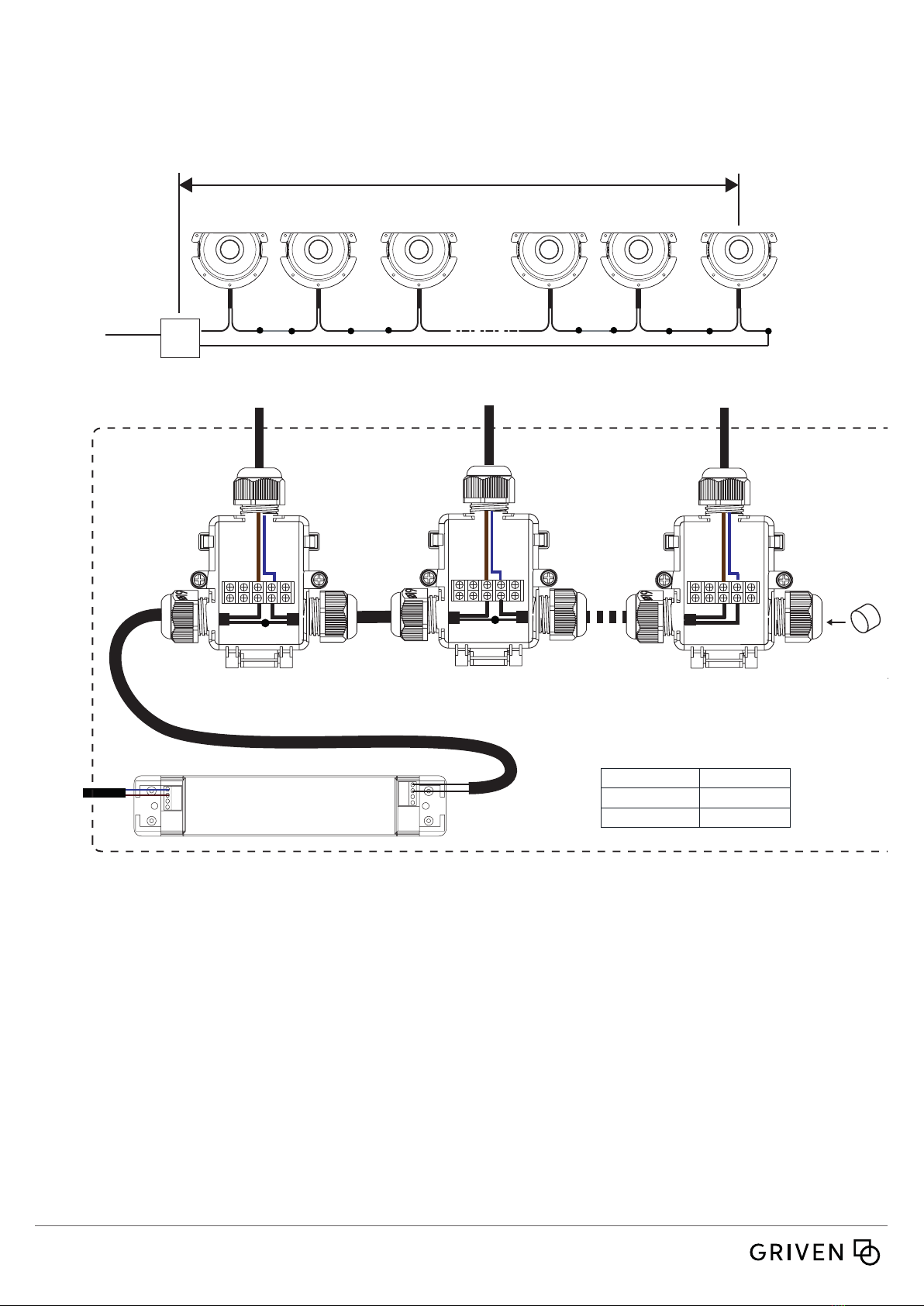
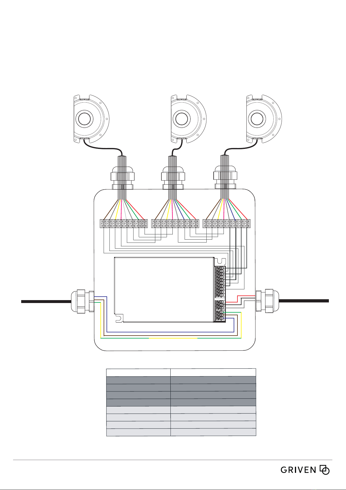
-Connect the fi xtures to each other only when disconnected from mains.
- Never leave cables and connectors unconnected or unprotected for long periods.
- Disconnect power before installing or servicing to avoid electrical shock.
- Disconnect power before any connection operation.
- Check voltage and frequency before powering the fi xture. Do not exceed fi xture
specifi ed voltage.
- Do not handle the unit with wet hands or in wet environments.
- Apply to qualifi ed staff for any maintenance service not described in this instruc-
tions manual.
- Do not exceed the maximum quantity of fi xtures per line in order to avoid power
surges.
- Before powering the unit, ensure to use cables and connectors with proper
section and length, according to its power consumption.
- Fix the projector by using screws, hooks or other adequate supports that can
bear its weight.
- If the external fl exible cable of this appliance is damaged, it must only be repla-
ced by the manufacturer, its assistance service or equivalent qualifi ed personnel in
order to avoid hazards.
- Integrated temperature control, the projector reduces power when Ta >35°C.
- The luminaire should be positioned so that prolonged observation of the luminaire
at a distance of less than 2 meters (6.56 ft) is not expected.
- Questo prodotto deve essere installato secondo le normative locali, da personale
specializzato. La mancata osservanza delle istruzioni di installazione può portare
a situazioni di pericolo all’incolumità della persone.
- Non fi ssare la sorgente luminosa durante il suo funzionamento.
- Apparecchiatura sensibile alle sovratensioni. Si consiglia l’installazione di un
dispositivo di protezione delle sovratensioni (SPD) sull’impianto elettrico per
attenuare l’intensità di questi fenomeni proteggendo gli apparecchi dal rischio che
vengano danneggiati.
- E’ consigliato l’uso di un adeguato interruttore magnetotermico/differenziale sulla
linea di alimentazione.
- Collegare tra loro i proiettori solo quando nessuno di essi è collegato alla rete
elettrica.
- Non lasciare mai per lungo tempo agli agenti atmosferici cavi e connettori non
collegati o non protetti.
- Togliere l’alimentazione prima di effettuare qualsiasi operazione all’interno
dell’apparecchiatura.
- Togliere l’alimentazione prima di effettuare qualsiasi operazione di connessione
tra gli apparecchi.
- Prima di connettere l’apparecchio alla rete elettrica, verifi cate la compatibilità di
tensione e frequenza.
- Non maneggiate il prodotto con mani bagnate o in presenza di acqua.
- Rivolgersi ad un tecnico qualifi cato per qualsiasi operazione di manutenzione
ordinaria non descritta nel presente manuale.
- Non superare il numero massimo specifi cato di apparecchi per linea per evitare
pericolori sovraccarichi di corrente.
- Prima di effettuare le connessioni verifi care la portata dei cavi / connettori e la
lunghezza dei cavi tenendo conto dell’assorbimento del prodotto.
- Fissare il proiettore con viti, ganci o altri supporti in grado di sostenerne il peso.
- Se il cavo fl essibile esterno di questo apparecchio vienne danneggiato, deve
essere sostituito esclusivamente dal produttore, dal suo servizio di assistenza o da
personale qualifi cato equivalente, al fi ne di evitare pericoli.
- Controllo della temperatura integrato, il proiettore reduce la potenza ad una
Ta >35°C
- l’apparecchio di illuminazione dovrebbe essere posizionato in modo che non sia
prevista un’osservazione prolungata dell’apparecchio ad una distanza inferiore a
2 metri.
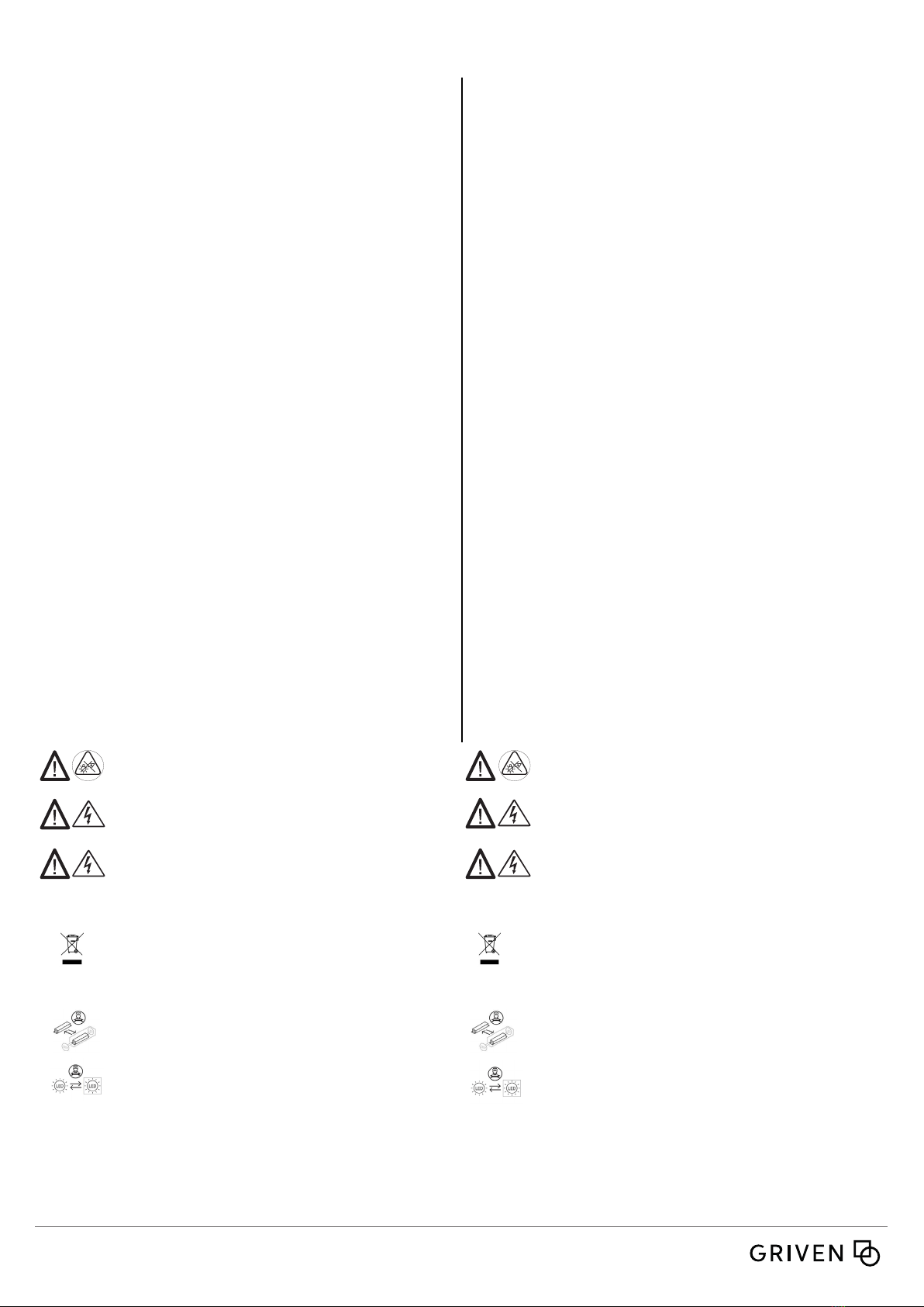
CAUTION: Prolonged staring at the LED source should be
avoided by placing the xture in a proper position.
ATTENZIONE! Fissare la sorgente LED per un periodo prolungato
va evitato posizionando l’apparecchio nella posizione appropriata.
WARNING ! Fixing and connecting operations must
mandatorily be carried out by qualied personnel only !
ATTENZIONE ! Le operazioni di ssaggio e collegamento
devono essere eseguite solo e obbligatoriamente da perso-
nale qualicato!
WARNING ! Make sure that power supply is o before
connecting or disconnecting xtures !
ATTENZIONE ! Assicurarsi che l’alimentazione sia spenta
prima di collegare o scollegare i dispositivi!
Replaceable control gear by a professional Alimentatore sostituibile da un professionista
Replaceable (LED only) light source by a professional Sorgente luminosa (solo LED) sostituibile da un
professionista
La possibilità di riutilizzare alcune parti elettriche del disposi-
tivo è subordinata alla totale responsabilità dell’utilizzatore.
Nell’etichetta è stato riportato il simbolo indicato nel D.lgs n.49
del14Marzo2014cherecepisceladirettiva2012/19/UE,ilquale
indica la necessità di smaltire il prodotto nei riuti dierenzia-
ti, nello specico nei riuti di tipo elettrico ed elettronico. Fare
riferimento al centro di raccolta riuti situato nella Vostra zona.
The possibility of reusing some electrical parts of the devi-
ce is subject to the total responsibility of the user. The la-
bel shows the symbol indicated in Legislative Decree n.49
of 14 March 2014 which transposes Directive 2012/19 / EU,
which indicates the need to dispose of the product in sepa-
rate waste, specically in electrical waste. and electronic.
Refer to the waste collection center located in your area.
This product contains a light source of energy eciency
class:
Questo prodotto contiene una sorgente luminosa di classe
di ecienza energetica:

Half Moon Recessed Rev. 1.0
page 3 of 9
551130
Installation - Installazione
ADDRESS THIS SIDE TO THE WALL
DRAINAGE
MATERIAL SOIL
CONCRETE
SECTION VIEW
SECTION VIEW
SECTION VIEW
SECTION VIEW
SECTION VIEW
TILED CONCRETE
76 mm
2,99 inch
CONCRETE
SECTION VIEW
PAVING
HOLE
40 mm
SECTION VIEW
FIXTURE CABLE
SUPPLY CABLE
2 END TO END CONNECTOR
1 HEAT SHRINK TUBE
ADDRESS THIS SIDE TO THE WALL
DRAINAGE
MATERIAL SOIL
CONCRETE
SECTION VIEW
SECTION VIEW
SECTION VIEW
SECTION VIEW
SECTION VIEW
TILED CONCRETE
76 mm
2,99 inch
CONCRETE
SECTION VIEW
PAVING
HOLE
40 mm
SECTION VIEW
FIXTURE CABLE
SUPPLY CABLE
2 END TO END CONNECTOR
1 HEAT SHRINK TUBE
ADDRESS THIS SIDE TO THE WALL
DRAINAGE
MATERIAL SOIL
CONCRETE
SECTION VIEW
SECTION VIEW
SECTION VIEW
SECTION VIEW
SECTION VIEW
TILED CONCRETE
76 mm
2,99 inch
CONCRETE
SECTION VIEW
PAVING
HOLE
40 mm
SECTION VIEW
FIXTURE CABLE
SUPPLY CABLE
2 END TO END CONNECTOR
1 HEAT SHRINK TUBE
DRAINAGE PIPE
SOLID SOIL in concrete - Prearrange an adequate support for the formwork as well as a drainage system through a pipe that allows the
water to ow without creating stagnations.
TERRENO SOLIDO in cemento - Predisporre un adeguato supporto alla cassaforma ed un drenaggio attraverso un tubo che permetta all’
acqua di dreanare senza creare ristagni.
SOFT SOIL - Arrange an adequate water drainage system with pebbles.
TERRENO MORBIDO - Predisporre un adeguato drenaggio con ciotoli per il drenaggio dell’acqua.
Open the formwork on one side for the passage of the corrugated pipe. If necessary, also open it on the other side.
Rimuovere dalla cassaforma il primo tassello per il passaggio del tubo corrugato. Se necessario rimuovere anche il secondo tassello.
DRAINAGE PIPE
INSTALLAZIONE NON CORRETTA
INCORRECT INSTALLATION

Half Moon Recessed Rev. 1.0
page 4 of 9
551130
ADDRESS THIS SIDE TO THE WALL
DRAINAGE
MATERIAL SOIL
CONCRETE
SECTION VIEW
SECTION VIEW
SECTION VIEW
SECTION VIEW
SECTION VIEW
TILED CONCRETE
76 mm
2,99 inch
CONCRETE
SECTION VIEW
PAVING
HOLE
40 mm
SECTION VIEW
FIXTURE CABLE
SUPPLY CABLE
2 END TO END CONNECTOR
1 HEAT SHRINK TUBE
ADDRESS THIS SIDE TO THE WALL
DRAINAGE
MATERIAL SOIL
CONCRETE
SECTION VIEW
SECTION VIEW
SECTION VIEW
SECTION VIEW
SECTION VIEW
TILED CONCRETE
76 mm
2,99 inch
CONCRETE
SECTION VIEW
PAVING
HOLE
40 mm
SECTION VIEW
FIXTURE CABLE
SUPPLY CABLE
2 END TO END CONNECTOR
1 HEAT SHRINK TUBE
Insert the pipe into the formwork and then x it to the ground through the specic xing holes.
ATTENTION: Point the at side of the formwork towards the wall as shown in the image below.
Posizionare il tubo corrugato nell’apposita apertura ricavata nella cassaforma e successimente ssare la cassaforma al terreno utilizzando
gli appositi fori di ssaggio. ATTENZIONE Orientare la faccia piana della cassaforma parallelamente al muro come indicato nell’immagine.
Fill with cement up to the level of the cap and clean o any material in excess that may prevent the removal of the cap
Riempire con cemento no al livello del tappo e rimuovere l’eventuale materiale in eccesso che possa impedire la rimozione del tappo.
ADDRESS THIS SIDE TO THE WALL
DRAINAGE
MATERIAL SOIL
CONCRETE
SECTION VIEW
SECTION VIEW
SECTION VIEW
SECTION VIEW
SECTION VIEW
TILED CONCRETE
76 mm
2,99 inch
CONCRETE
SECTION VIEW
PAVING
HOLE
40 mm
SECTION VIEW
FIXTURE CABLE
SUPPLY CABLE
2 END TO END CONNECTOR
1 HEAT SHRINK TUBE
ATTENZIONE: versare il cemento no al livello del tappo.
ATTENTION: pour cement up to the level of the cap.
ADDRESS THIS SIDE TO THE WALL
DRAINAGE
MATERIAL SOIL
CONCRETE
SECTION VIEW
SECTION VIEW
SECTION VIEW
SECTION VIEW
SECTION VIEW
TILED CONCRETE
76 mm
2,99 inch
CONCRETE
SECTION VIEW
PAVING
HOLE
40 mm
SECTION VIEW
FIXTURE CABLE
SUPPLY CABLE
2 END TO END CONNECTOR
1 HEAT SHRINK TUBE
ATTENTION: To facilitate the removal of the cap, its recomanded to use a release agent for formworks.
ATTENZIONE: Per facilitare l’estrazione del tappo si consiglia di utilizzare un agente distaccante per cassaforme.
ADDRESS THIS SIDE TO THE WALL
DRAINAGE
MATERIAL SOIL
CONCRETE
SECTION VIEW
SECTION VIEW
SECTION VIEW
SECTION VIEW
SECTION VIEW
TILED CONCRETE
76 mm
2,99 inch
CONCRETE
SECTION VIEW
PAVING
HOLE
40 mm
SECTION VIEW
FIXTURE CABLE
SUPPLY CABLE
2 END TO END CONNECTOR
1 HEAT SHRINK TUBE
Ø25mm
1.0in
Ø50mm
2.0in
76mm
2,99in
2mm
0.1in
60mm
2.4in
Ø128mm
5.0in
Ø140mm
5.5in
100mm
3.9in
TWO SIDE
KNOCKOUT HOLE
140mm
5.5in
N° 5 HOLES
Ø 5 mm [ 0,19 in]

Half Moon Recessed Rev. 1.0
page 5 of 9
551130
ADDRESS THIS SIDE TO THE WALL
DRAINAGE
MATERIAL SOIL
CONCRETE
SECTION VIEW
SECTION VIEW
SECTION VIEW
SECTION VIEW
SECTION VIEW
TILED CONCRETE
76 mm
2,99 inch
CONCRETE
SECTION VIEW
PAVING
HOLE
40 mm
SECTION VIEW
FIXTURE CABLE
SUPPLY CABLE
2 END TO END CONNECTOR
1 HEAT SHRINK TUBE
ADDRESS THIS SIDE TO THE WALL
DRAINAGE
MATERIAL SOIL
CONCRETE
SECTION VIEW
SECTION VIEW
SECTION VIEW
SECTION VIEW
SECTION VIEW
TILED CONCRETE
76 mm
2,99 inch
CONCRETE
SECTION VIEW
PAVING
HOLE
40 mm
SECTION VIEW
FIXTURE CABLE
SUPPLY CABLE
2 END TO END CONNECTOR
1 HEAT SHRINK TUBE
Before installing the xture, remove the cap from
the formwork by using pliers.
Prima di iniziare l’installazione dell’apparecchio
rimuovere il tappo della cassaforma.
Facilitare l’operazione aiutandosi con una pinza
per imprimere maggiore forza.
Connect the xture to the power cable. Put the heat shrink tube tted with glue “1” on the power cable. Connect to the mains through the
connectors “2”, pressing them with the appropriate tool “3”. Heat the tube using the heater “ 4” until it completely shrinks. This connection
will feature an IP67 protection degree.
3
4
Connettere il proiettore al cavo di alimentazione. Inserire la guaina termorestringente con collante “1” sul cavo di alimentazione.
Eettuare il collegamento alla rete tramite i connettori testa - testa “2”, premendoli con l’apposito attrezzo “3”.
Riscaldare il tubo utilizzando un riscaldatore per tubi termoretraibili “4” no a completo restringimento.
La connessione così ottenuta ha un grado di protezione IP67.

Half Moon Recessed Rev. 1.0
page 6 of 9
551130
ADDRESS THIS SIDE TO THE WALL
DRAINAGE
MATERIAL SOIL
CONCRETE
SECTION VIEW
SECTION VIEW
SECTION VIEW
SECTION VIEW
SECTION VIEW
TILED CONCRETE
76 mm
2,99 inch
CONCRETE
SECTION VIEW
PAVING
HOLE
40 mm
SECTION VIEW
FIXTURE CABLE
SUPPLY CABLE
2 END TO END CONNECTOR
1 HEAT SHRINK TUBE
ADDRESS THIS SIDE TO THE WALL
DRAINAGE
MATERIAL SOIL
CONCRETE
SECTION VIEW
SECTION VIEW
SECTION VIEW
SECTION VIEW
SECTION VIEW
TILED CONCRETE
76 mm
2,99 inch
CONCRETE
SECTION VIEW
PAVING
HOLE
40 mm
SECTION VIEW
FIXTURE CABLE
SUPPLY CABLE
2 END TO END CONNECTOR
1 HEAT SHRINK TUBE
ADDRESS THIS SIDE TO THE WALL
DRAINAGE
MATERIAL SOIL
CONCRETE
SECTION VIEW
SECTION VIEW
SECTION VIEW
SECTION VIEW
SECTION VIEW
TILED CONCRETE
76 mm
2,99 inch
CONCRETE
SECTION VIEW
PAVING
HOLE
40 mm
SECTION VIEW
FIXTURE CABLE
SUPPLY CABLE
2 END TO END CONNECTOR
1 HEAT SHRINK TUBE
When connected, roll up the cable inside the
formwork and put the xture into the formwork
itself.
Dopo aver eettuato le connessioni arrotolare il
cavo all’interno della cassaforma e posizionare
l’apparecchio all’interno della cassaforma.

Half Moon Recessed Rev. 1.0
page 7 of 9
551130
AL4324/700 POWER SUPPLY UNIT
Costant Current 900 mA
120-277 Vac
50- 60 Hz
A
CABLE/CAVI
Brown/Marrone
Blue/Blu
USE/UTILIZZO
+
-
+ -
-
Vac
+ - + - + - + - + -
LINE END CAP
INCLUDED IN AL5296
TAPPO DI FINE LINEA
INCLUSO IN AL5296
MINIMUM 1FIXTURE MAXIMUM 10 FIXTURES
50 m
AL5296
3 WAY JUNCTION BOX
AL5296
3 WAY JUNCTION BOX
AL5296
3 WAY JUNCTION BOX
LED -
LED +
L
N
Half Moon Recessed W
Conguration examples / Esempi di congurazioni

Half Moon Recessed Rev. 1.0
page 8 of 9
551130
LED OUTPUT 1 +
LED OUTPUT 1 -
LED OUTPUT 2 -
LED OUTPUT 2 +
LED OUTPUT 3 +
LED OUTPUT 3 -
LED OUTPUT 4 -
LED OUTPUT 4 +
RED+
RED-
GREEN +
GREEN -
BLUE -
WHITE +
WHITE -
RED+
RED-
GREEN +
GREEN -
BLUE +
BLUE -
WHITE +
WHITE -
RED+
RED-
GREEN +
BLUE +
BLUE -
WHITE -
ROSSO / RED
CABLE/CAVI USE/UTILIZZO
VERDE / GREEN
GIALLO / YELLOW
GRIGIO / GREY
ROSA / PINK
BLU / BLUE
MARRONE / BROWN
BIANCO / WHITE
RED LED + / LED ROSSO +
RED LED - / LED ROSSO -
GREEN LED - / LED VERDE -
GREEN LED + / LED VERDE +
BLUE LED + / LED BLU+
BLUE LED - / LED BLU -
WHITE LED - / LED BIANCO -
WHITE LED + / LED BIANCO +
LED CODE NTC +
LED CODE NTC -
DMX IN +
DMX IN -
GROUND
DMX SHIELD
L
N
120-250 Vac
50- 60 Hz
DMX
WHITE +
GREEN -
BLUE +
MAXIMUM 10 FIXTURES
Distance between PSU and last fixture: 100m
Half Moon Recessed RGBW

Half Moon Recessed Rev. 1.0
page 9 of 9
551130
Note: Allowed operation only between sunset and sunrise
Nota: Accensione dell’apparecchio ammessa soltanto tra gli orari di tramonto e alba
This manual suits for next models
4
Table of contents
Other Griven Landscape Lighting manuals
Popular Landscape Lighting manuals by other brands

AMP Lighting
AMP Lighting Sol Box Brass ASDL-2014-B-BZ Installation & maintenance guide

AMP Lighting
AMP Lighting APL-3016-4-B-BZ Installation & maintenance guide

Portfolio
Portfolio SLS10BR quick start guide

AMP Lighting
AMP Lighting SleekPro MR11 Downlight Installation & maintenance guide

Pontec
Pontec PondoSolar Lily LED Set 3 operating instructions

AMP Lighting
AMP Lighting AlpinePro Path Light Installation & maintenance guide