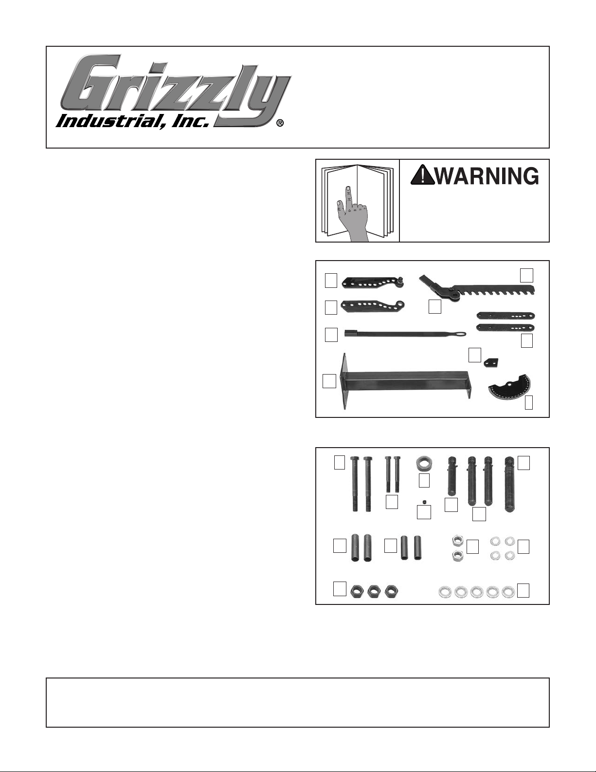
Grizzly T30860 User manual

Figure 1. Main components inventory.
A
BC
D
EF
G
H
I
Figure 2. Packaged components inventory.
J
K
L
MNO
P
Q R S T
UV
To reduce your risk of
serious injury, read this
entire manual BEFORE
using machine.
For questions or help with this product contact Tech Support at (570) 546-9663 or techsupport@grizzly.com
MODEL T30860
MANDREL TUBE
BENDER
INSTRUCTIONS
COPYRIGHT © DECEMBER, 2019 BY GRIZZLY INDUSTRIAL, INC.
NO PORTION OF THIS MANUAL MAY BE REPRODUCED IN ANY SHAPE
OR FORM WITHOUT THE WRITTEN APPROVAL OF GRIZZLY INDUSTRIAL, INC.
#KS20842 PRINTED IN CHINA
Introduction
The T30860 Mandrel Tube Bender provides a
stable, durable steel platform for tube bending. It
includes a floor-mounted stand, bend angle indi-
cator, and removable 41" handle.
Round Tube Capacity ................................. 1⁄2"–2"
Square Tube Capacity .................................. 1"–2"
Maximum Bending Angle .............................. 180°
Weight ........................................................98 lbs.
Specifications
Main Components (Figure 1) Qty
A. Lower Frame Link ........................................ 1
B. Upper Frame Link ........................................ 1
C. Swing Lever w/Ratchet Pin.......................... 1
D. Ratchet ........................................................ 1
E. Handle ......................................................... 1
F. Drive Links ................................................... 2
G. Stand ........................................................... 1
H. Frame Base ................................................. 1
I. Bend Angle Indicator ................................... 1
Packaged Components (Figure 2) Qty
J. Hex Bolts M20-2.5 x 175 ............................. 2
K. Hex Bolts M14-2 x 110 ................................. 2
L. Collar ........................................................... 1
M. Set Screw M8-1.25 x 8 ................................ 1
N. U-Strap Pin .................................................. 1
O. Drive Pins .................................................... 2
P. Frame Pin .................................................... 1
Q. Frame Spacers ............................................ 2
R. Drive Link Spacers ...................................... 2
S. Hex Nuts M14-2 ........................................... 2
T. Flat Washers 14mm .................................... 4
U. Hex Nuts M20-2.5 ....................................... 3
V. Flat Washers 20mm .................................... 5
Inventory
V1.12.19

Upper
Frame Link
#5
Lower
Frame Link
Stand
Flat Washer
20mm
M20-2.5 x 175
Hex Bolt
Flat Washer
20mm
M20-2.5
Hex Nut
Flat Washer
20mm
M20-2.5
Hex Nut
Drive Pin Frame Pin
Collar
Frame
Spacer
Frame Base
Ratchet
Swing Lever
w/Ratchet Pin
Bend Angle
Indicator
Figure 4. Frame assembly setup.
Machine Base
Concrete
Lag Screw
Lag Shield Anchor
Flat Washer
Drilled Hole
Figure 3. Proper method for anchoring a
machine to a concrete floor.
This machine and its
components are very
heavy. Get lifting help or
use power lifting equip-
ment such as a forklift to
move heavy items.
Eye injury hazard! Always
wear safety glasses when
using this machine.
-2- Model T30860 (Mfd. Since 12/19)
The machine must be fully assembled before it
can be operated. Before beginning the assembly
process, refer to Needed for Setup and gather
all listed items. To ensure the assembly process
goes smoothly, first clean any parts that are cov-
ered or coated in rust preventative.
Assembly
Frame Assembly Setup
1. Place frame base (see Figure 4) on stand
and verify holes are aligned.
2. Place lower frame link on top of frame base
as shown in Figure 4 and verify both are
aligned.
3. Verify swing lever and ratchet are right side
up, and swing lever is able to rotate almost a
full 180° (see Figure 4).
4. Insert frame spacer into swing lever and
collar, then position frame spacers between
upper and lower frame links (see Figure 4).
Needed for Setup
Recommend Tools Qty
Additional Person for Lifting ............................... 1
Safety Glasses (for each person) ....................... 1
Hex Wrench 4mm ............................................... 1
Open-End Wrench or Socket 20mm .................. 2
Open-End Wrench or Socket 14mm .................. 2
Cleaner/Degreaser ..............................As Needed
Disposable Shop Rags ........................As Needed
Anchoring
This machine MUST be anchored to the floor
before operating. Anchoring machinery to the
floor prevents tipping or shifting that may occur
during operation.
Lag shield anchors with lag screws (Figure 3) are
a popular way to anchor machinery to a concrete
floor, because the anchors sit flush with the floor
surface. However, anytime local codes apply, you
MUST follow the anchoring methodology speci-
fied by the code.

Frame
Pin
Drive
Pin
M14-2 x 110
Hex Bolt
14mm
Flat Washer
14mm
Flat Washer
M14-2
Hex Nut
Drive
Link
Drive
Link Drive Link
Spacer
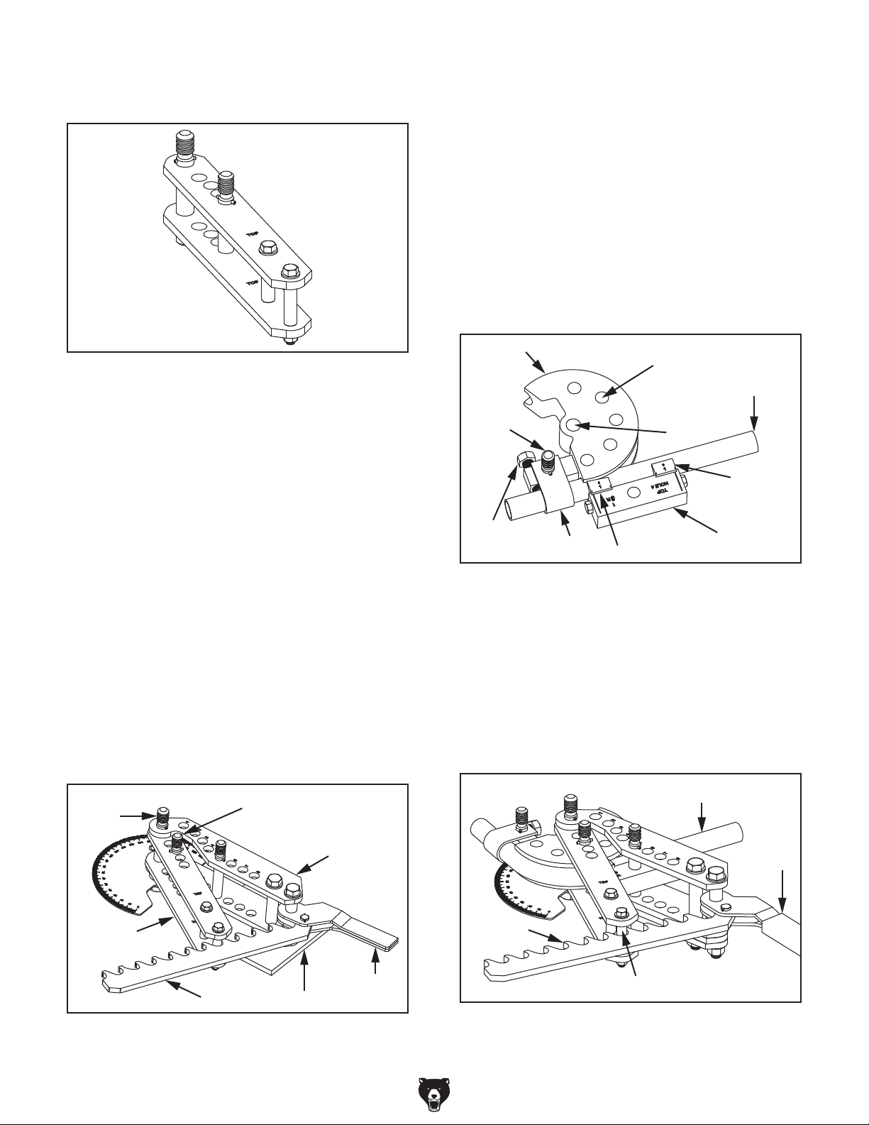
Figure 6. Drive link assembly setup.
Figure 5. Completed frame assembly.
Model T30860 (Mfd. Since 12/19) -3-
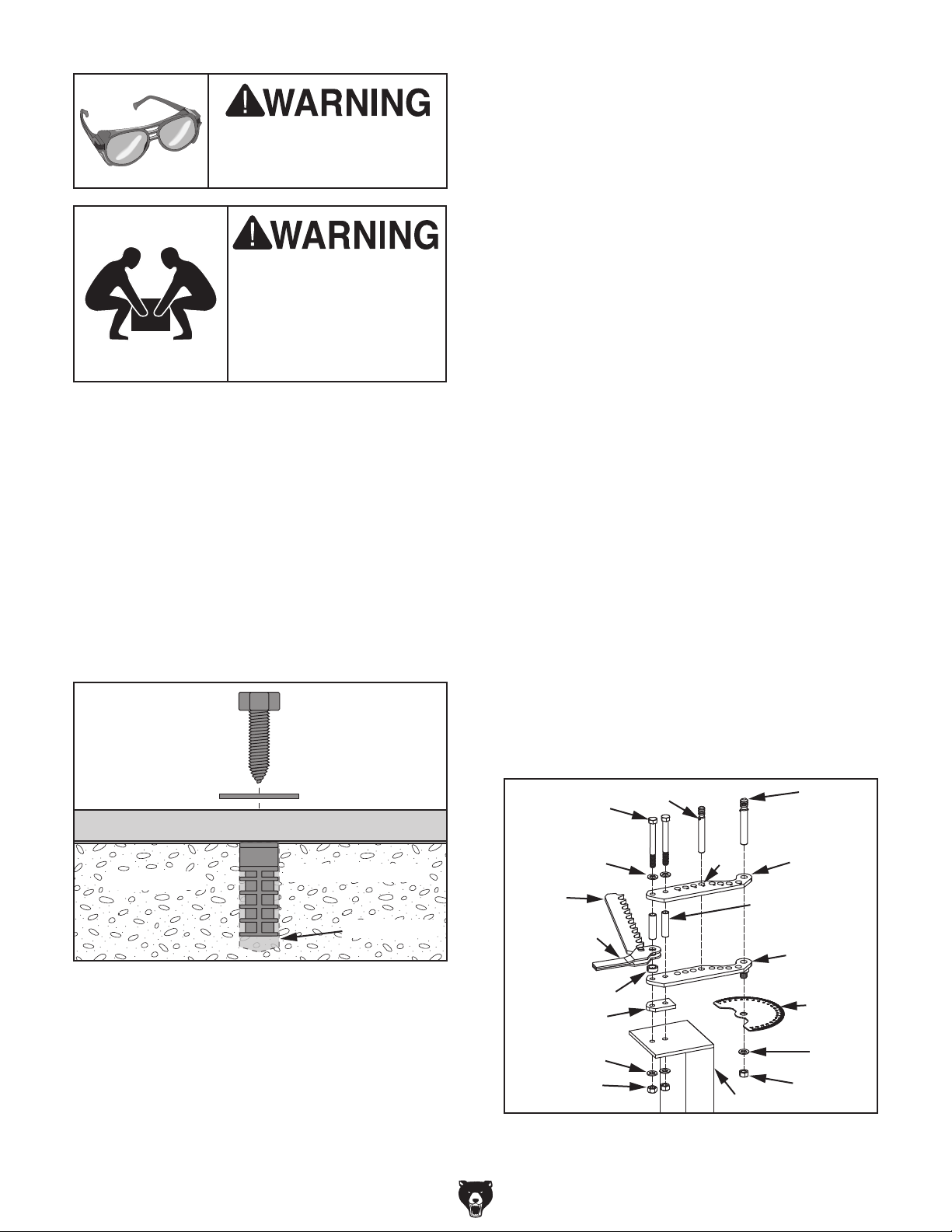
5. Insert M20-2.5 x 175 hex bolts with 20mm
flat washers through upper frame link, frame
spacers, swing lever, collar, lower frame
link, frame base, and stand (see Figure 4).
Secure with 20mm flat washers and M20-2.5
hex nuts (only hand tighten for now).
6. Insert frame pin through upper and lower
frame links (see Figure 4).
7. Insert drive pin into #5 hole as shown in
Figure 4.
8. Fully tighten both hex nuts installed in Step
5. Verify drive pin and frame pin are able to
slide through their respective holes.
9. Raise swing lever to middle of frame spacer
and lock into position by tightening set screw
on collar with 4mm hex wrench.
10. Install bend angle indicator, 20mm flat wash-
er, and M20-2.5 hex nut onto lower frame link
(see Figure 4) and hand tighten.
Note: This nut should never be tightened with
a wrench. This allows the bend angle indica-
tor to be adjusted while bending.
11. Verify frame is assembled as shown in
Figure 5.
Drive Link Assembly Setup
1. Place both drive links (see Figure 6)on their
side with "TOP" stamp facing same direction.
Note: Drive link "TOP" stamp must face
same direction on both drive links since three
of four drive holes are offset to the right.
2. Insert M14-2 x 110 hex bolts with 14mm flat
washers into upper drive link holes shown in
Figure 6.
3. Install drive link spacers (see Figure 6)over
hex bolts and insert threaded end of hex bolts
through lower drive link holes.
4. Secure hex bolts with 14mm flat washers and
M14-2 hex nuts, and hand tighten.
5. Insert frame pin and drive pin through drive
link holes shown in Figure 6.
Note: The frame pin is shared between
assemblies for alignment purposes only dur-
ing setup.
6. Fully tighten both hex nuts installed in Step
4. Verify drive pin and frame pin are able to
slide through their respective holes.

Figure 7. Completed drive link assembly.
Frame
Pin Drive Pin
Frame
Assembly
Swing
Lever
Ratchet Stand
Drive
Assembly
Figure 8. Completed bender assembly.
Forming
Die
Drive
Holes (5)
Frame
Hole
Round
Tubing
Straight
Insert
Angled Insert
Followbar
U-Strap
Pin
U-Strap
Bolt U-Strap
Figure 9. Die set with drive holes.
Round Tubing
Handle
Ratchet
Outer Drive Link Spacer
Figure 10. Engaging outer drive link spacer.
-4- Model T30860 (Mfd. Since 12/19)
7. Verify drive link is assembled as shown in
Figure 7.
Bender Assembly Setup
1. Remove frame pin and drive pin from drive
link assembly (see Figure 8).
2. Insert frame pin hole portion of drive link
assembly between frame pin holes of frame
assembly (see Figure 8). Verify alignment of
all four frame pin holes.
3. Insert frame pin through frame assembly and
drive link assembly (see Figure 8).
4. Insert drive pin into drive link assembly (see
Figure 8).
Note: Drive pin location is determined by the
die set being installed.
5. Verify bender is assembled as shown in
Figure 8 before installing die sets.
Die Sets With Drive Holes
1. Verify all pins are completely seated and die
set is installed according to manufacturer's
instructions (see Figure 9).
2. Place tubing into die set and tighten U-strap
bolt (see Figure 9).
3. Install handle onto swing lever and rotate
swing lever counterclockwise until it stops.
4. Engage ratchet onto outer drive link spacer,
as shown in Figure 10.
5. Lightly pull handle clockwise to preload tub-
ing. DO NOT pull hard enough to bend tubing.
Bending Operations
The T30860 is capable of bending round tubing
between 1⁄2"–2" in diameter, and square tubing
between 1"–2" in diameter. The machine supports
die sets with or without drive holes.

Pointer Lock Bolt
Bend Angle Indicator
Die Block
Round Tubing
Pointer
Figure 11. Die set pointer location.
Handle
Swing Lever
Ratchet
Drive Link
Spacer
Figure 12. Removing tube from assembly.
Forming
Die
Frame
Hole
Round
Tubing
Straight
Insert
Angled Insert
Followbar
Drive
Pin
U-Strap
U-Strap
Bolt
Figure 13. Die set without drive holes.
Model T30860 (Mfd. Since 12/19) -5-
Die Sets Without Drive Holes
1. Verify all pins are completely seated and die
set is installed according to manufacturer's
instructions (see Figure 13).
15. Rotate swing lever and ratchet counterclock-
wise as shown in Figure 12.
16. Remove handle from swing lever and insert
diagonally through drive link assembly spac-
ers (see Figure 12).
17. Pull handle counterclockwise until followbar
releases tubing.
18. Carefully remove tubing from assembly.
6. Rotate bend angle indicator until die set
pointer is at 0° (see Figure 11).
7. Pull handle clockwise with enough force
to bend tubing until swing lever stops (see
Figure 10 on Page 4).
8. Slowly rotate handle counterclockwise until
ratchet disengages.
Note: If ratchet disengages too quickly the
tubing could move out of position.
9. Re-engage ratchet at next closest tooth and
pull handle clockwise with enough force to
bend tubing until swing lever stops.
10. Repeat Steps 6–8 until last ratchet tooth is
engaged.
11. Rotate handle counterclockwise until swing
lever stops.
12. Remove drive pin from drive link assembly
(see Figure 8 on Page 4).
13. Rotate drive link assembly counterclockwise,
then insert drive pin into next drive hole in
forming die. Verify drive pin is fully seated
before continuing.
Note: Take care to maintain tube position
when making adjustments.
14. Repeat Steps 6–12 until desired bend angle
is reached.
Table of contents
Other Grizzly Construction Equipment manuals