Grizzly T33952 User manual

COPYRIGHT © NOVEMBER, 2023 BY GRIZZLY INDUSTRIAL, INC.
WARNING: NO PORTION OF THIS MANUAL MAY BE REPRODUCED IN ANY SHAPE
OR FORM WITHOUT THE WRITTEN APPROVAL OF GRIZZLY INDUSTRIAL, INC.
#JM22871 PRINTED IN CHINA V1.11.23
***Keep for Future Reference***
MODEL T33952/T33953/T33954
ACOUSTIC GUITAR KIT
OWNER'S MANUAL
(For models manufactured since 09/23)

Some dust created by power sanding, sawing, grinding, drilling, and
other construction activities contains chemicals known to the State
of California to cause cancer, birth defects or other reproductive
harm. Some examples of these chemicals are:
• Lead from lead-based paints.
• Crystalline silica from bricks, cement and other masonry products.
• Arsenic and chromium from chemically-treated lumber.
Your risk from these exposures varies, depending on how often you
do this type of work. To reduce your exposure to these chemicals:
Work in a well ventilated area, and work with approved safety equip-
ment, such as those dust masks that are specially designed to filter
out microscopic particles.

INTRODUCTION............................................................................................................................... 2
Contact Info.................................................................................................................................2
Description ..................................................................................................................................2
Manual Accuracy.........................................................................................................................2
Identification ................................................................................................................................3
Glossary Of Terms ......................................................................................................................4
SECTION 1: SAFETY....................................................................................................................... 5
SECTION 2: SETUP ......................................................................................................................... 6
Unpacking ...................................................................................................................................6
Planning & Preparation ...............................................................................................................6
Needed for Setup ........................................................................................................................6
Inventory......................................................................................................................................7
SECTION 3: SANDING .................................................................................................................... 8
Body ............................................................................................................................................8
Neck ............................................................................................................................................8
Bridge ..........................................................................................................................................8
Fitting Neck to Body....................................................................................................................9
SECTION 4: ASSEMBLY................................................................................................................ 10
Attaching ..................................................................................................................................10
Neck to Body.............................................................................................................................10
Installing Truss Rod...................................................................................................................11
Attaching Fretboard...................................................................................................................12
Determining Bridge Location.....................................................................................................13
Attaching Nut.............................................................................................................................15
Preparing to Finish ....................................................................................................................15
Painting/Finishing ......................................................................................................................16
Attaching Bridge........................................................................................................................16
Fitting Bridge Pins .....................................................................................................................17
Attaching Sound Hole Decal .....................................................................................................18
Installing Tuning Machines........................................................................................................19
Installing Strings........................................................................................................................20
Setting String Height .................................................................................................................20
Guitar Setup ..............................................................................................................................22
SECTION 5: ACCESSORIES ......................................................................................................... 23
SECTION 6: PARTS ....................................................................................................................... 24
Main...........................................................................................................................................24
WARRANTY & RETURNS.............................................................................................................. 25
Table of Contents

-2- Model T33952/53/54 (Mfd. Since 09/23)
Contact Info
INTRODUCTION
Manual Accuracy
We are proud to provide a high-quality owner's
manual with your new instrument!
We make every effort to be exact with the instruc-
tions, specifications, drawings, and photographs
in this manual. Sometime we make mistakes, and
our policy of continuous improvement also means
that sometimes the instrument you receive is
slightly different than shown in the manual.
If you find this to be the case, and the difference
between the manual and instrument leaves you
in doubt, check our website (grizzly.com) for an
updated version. We post current manuals and
manual updates for free on our website.
Alternatively, you can call our Technical Support
for help. Before calling, gather all material and
instructions that came with your instrument for
easy reference. This will make providing you
proper technical support much easier. It also will
help us determine if updated documentation is
available for your instrument.
We stand behind our instruments! If you have
questions or need help, contact us using the infor-
mation below. Before contacting, make sure you
gather all the information regarding your instru-
ment. This will aid us in helping you faster.
Grizzly Technical Support
1815 W. Battleeld
Springeld, MO 65807
Phone: (570) 546-9663
Email: techsupport@grizzly.com
We want your feedback on this manual. What did
you like about it? Where could it be improved?
Please take a few minutes to give us feedback.
Grizzly Documentation Manager
P.O. Box 2069
Bellingham, WA 98227-2069
Email: manuals@grizzly.com
NOTICE
WE STRONGLY RECOMMEND that you read
books, review industry trade magazines, or
get formal training before beginning any
projects. Regardless of the contents in
this Manual, Grizzly Industrial will not be
held liable for accidents caused by lack
of training.
T33952
T33953
T33954
The Grizzly acoustic guitar kits are available in
three veneer options:
—T33952 Quilted Maple Veneer
—T33953 Fiddleback Maple Veneer
—T33954 Solid Koa
Description

Model T33952/53/54 (Mfd. Since 09/23) -3-
Identification
Become familiar with the names and locations of the features shown below to better understand the
instructions in this manual.
There is potential danger when operating
woodworking machinery. Accidents are fre-
quently caused by lack of familiarity or fail-
ure to pay attention. Use any machines with
respect and caution to decrease the risk of
operator injury. If normal safety precautions
are overlooked or ignored, serious personal
injury may occur.
No list of safety guidelines can be com-
plete. Every shop environment is different.
Always consider safety first, as it applies
to your individual working conditions. Use
tools and any machinery with caution and
respect. Failure to do so could result in seri-
ous personal injury, damage to equipment,
or poor work results.
Bridge
Saddle Body Strings
Fret
Board Neck Tuning
Machines
Headstock
Nut
Frets
Fret Inlay/
Markers
Sound
Hole
12th Fret
Sound
Board

-4- Model T33952/53/54 (Mfd. Since 09/23)
The following is a list of common definitions, terms and phrases used throughout this manual as they relate
to this guitar and music in general. Become familiar with these terms for assembling, adjusting, or operating
this instrument.
Acoustic: An instrument that makes sound with
no amplification, utilizing its own construction
and soundhole to project tone and volume.
Action: Setup of strings in relation to instrument
body and neck. Most commonly this relates to
height of strings above fretboard.
Back: Rear face of instrument.
Body: Instrument housing composed of three
main parts—top, sides and back—and holds
bridge on top, connecting to neck of instrument.
Bridge: Wooden piece glued on top of instrument
body and holds saddle. There are four main
types of bridges: slotted, tie bar, through body,
and pin.
Fretboard: Area of neck over which strings run
and into which frets are mounted. Fretboard is
where your fretting hand holds notes by press-
ing down on strings between frets.
Finish: The manufacture or decoration of an
instrument by giving it an attractive surface
appearance.
Fret: Thin strips of metal set into neck of an instru-
ment to allow changing notes.
Fret Markers: Dots inlaid in fretboard of instru-
ment to help finger placement and locating
notes.
Headstock: Flat piece of wood at top of neck that
holds tuning pegs and usually displays instru-
ment brand logo.
Inlay: Material inlaid into surface parts of
instrument.
Intonation: Ability of an instrument to play and
hold correct note at any point on neck. This usu-
ally refers to quality of an instrument’s construc-
tion, and ability for each fret, when depressed,
to sound correct note for its position.
Joint: Where neck meets body of instrument.
Neck: Wood that holds fretboard, and runs
between body of instrument and headstock.
Nut: A strip of material located at top end of
fretboard over which strings are held in slots
prior to tuning pegs.
Tuning Machine: Tuning pegs that work using
a gearing system to turn string post altering
instrument tone.
Tuning Peg: Tuning device that is turned to
tighten or loosen string.
Saddle: Section of instrument over which strings
are secured.
Scale Length: Dimension of string length mea-
sured between nut and saddle. Length needs
to be accurate in relation to placement of frets
to ensure accuracy in notes being played. Top
of 12th fret always denotes exact halfway point
of string.
Sound Board: Flat piece of wood that holds
bridge and sound hole.
Sound Hole: Hole in sound board of instrument
that projects sound.
Glossary Of Terms

Model T33952/53/54 (Mfd. Since 09/23) -5-
SECTION 1: SAFETY
Always wear safety glasses or goggles when operating equipment. Everyday glasses or reading glass-
es are not safety glasses. Be certain the safety glasses you wear meet the appropriate standards of
the American National Standards Institute (ANSI).
Because there are various ways to cut and join wood, you can make substitutions for the methods
stated in this plan. We try to suggest the easiest methods possible. However, only you know your skills
with each piece of machinery. Never compromise your safety by using a cutting method with which you
are not comfortable. Instead, find an alternative approach that will yield the same result.
These instructions assume that you are intimately familiar with the safe operation and use of woodwork-
ing machinery and woodworking tools, and understand the techniques used to reproduce this project.
If you do not qualify for both of these criteria, STOP building this project for your own safety. Read and
understand the owner’s manual for the machinery you intend to use, take a woodworking class or visit
your local library for more information. Woodworking machinery and tools are inherently dangerous,
because they use sharp edges that can and will cause serious personal injury including amputation
and death. Do not underestimate the ability of these tools and machinery to cause injury. Never oper-
ate any tool without all guards in place and always wear approved safety glasses. For your own safety,
please heed this warning.

-6- Model T33952/53/54 (Mfd. Since 09/23)
SECTION 2: SETUP
Needed for SetupUnpacking
This instrument was carefully packaged for safe
transport. When unpacking, separate all enclosed
items from packaging materials and inspect them
for shipping damage. If items are damaged,
please call us immediately at (570) 546-9663.
IMPORTANT: Save all packaging materials until
your are completely satisfied with the instrument
and have resolved any issues between Grizzly or
the shipping agent. You must have the original
packaging to file a freight claim. It is also extreme-
ly helpful if you need to return your instrument.
The majority of the wooden components in this kit
are fully machined from the factory and are ready
for assembly. A small amount of sanding and fin-
ishing is required to complete your guitar.
Description Qty
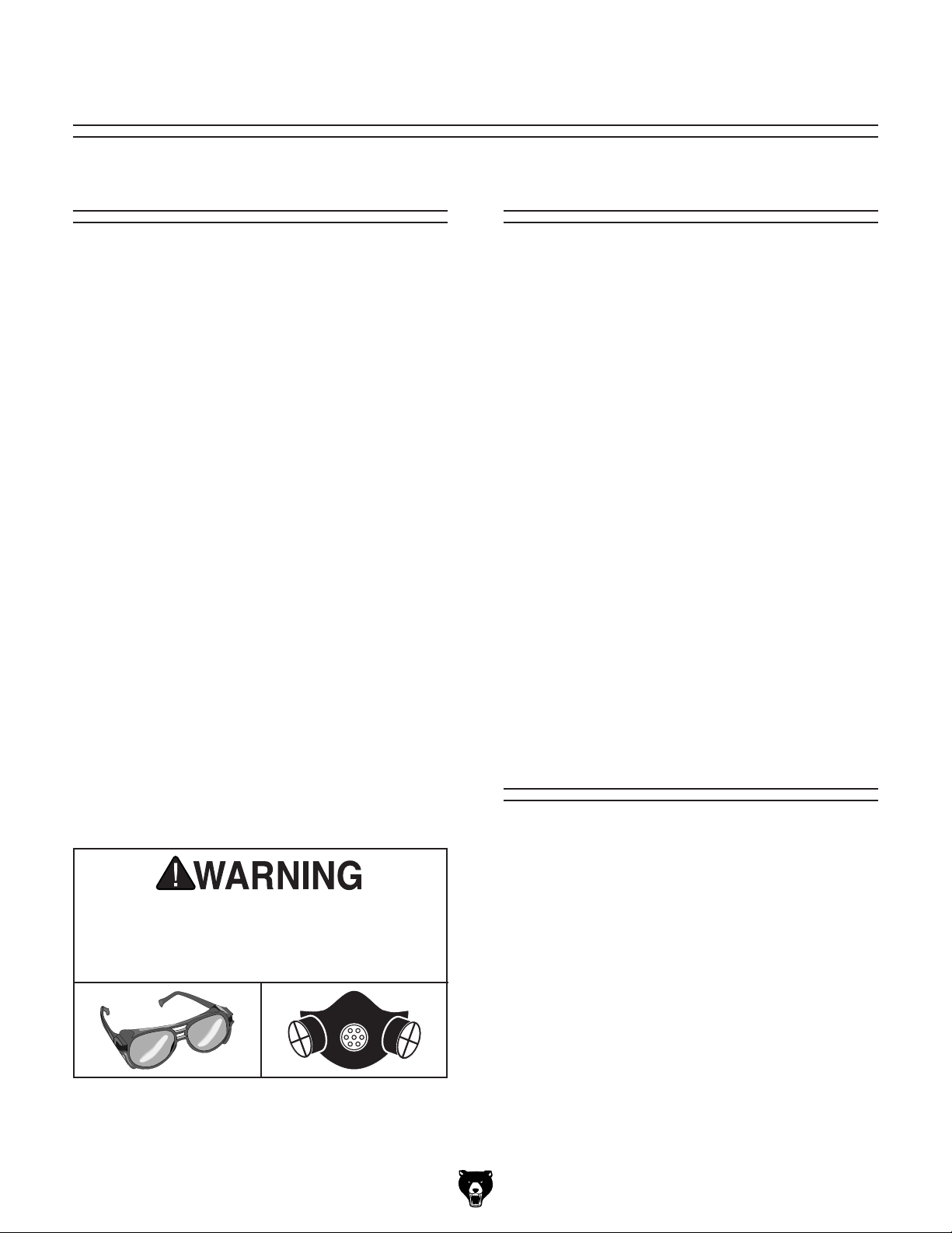
• Safety Glasses (per person)....................... 1
• NIOSH-Approved Respirator (per person)... 1
• Ratchet or Frame Clamp ............................ 1
• Hobby Knife or Chisel ................................ 1
• T-Handle Reamer (1⁄8" to 5⁄8") ..................... 1
• Drill Press or Cordless Drill w/Depth Stop... 1
• Forstner Bit 5⁄32".......................................... 1
• Sanding Block ............................................ 1
• Band Clamp................................................ 1
• Fine Tooth Saw (Coping, Fret, or Curved)..... 1
• Bridge Clamp (4" Minimum) ....................... 1
• Mini-Clamps (1" Minimum) ......... As Needed
• Straightedge (18" Minimum) ....................... 1
• Small File (Fine) ......................................... 1
• Rubber Bands ............................ As Needed
• 2" x 2" x 18" Wood Stock ........................... 1
• Thread or Thin String ................ As Needed
• Pencil.......................................................... 1
• Phillips Head Screwdriver #0 ....................... 1
• Wire Cutters ............................................... 1
• Precision Ruler ........................................... 1
• Disposable Nitrile Gloves ........... As Needed
• Wood Glue ................................. As Needed
• Super Glue ................................. As Needed
• Finishing Supplies ...................... As Needed
• Wood Filler/Putty ........................ As Needed
• Tack Cloth................................... As Needed
• Lint-Free Rags............................ As Needed
• Sandpaper #180, #240, #320 .... As Needed
• Sandpaper Wet/Dry #800, #1000,
#1200.......................................... As Needed
• Masking or Painter's Tape.......... As Needed
• C-Clamps (3" Minimum) ............. As Needed
• Masking paper............................ As Needed
• Tuning Fork (Optional)................................ 1
• Palm Sander (Optional).............................. 1
• Binding Tape (Optional).............. As Needed
Wear safety glasses during
the entire setup process!
Planning &
Preparation
Total time building this instrument will vary on
many factors. Variables such as glue manufactur-
ers instructions and curing time, temperature and
humidity at the time of building, and your schedule
are just a few of the factors that can affect the
length of time spent on this project.
Perhaps the biggest determinant of time spent
completing this instrument is the type of finish
and the finishing process used. Finishing this
instrument can be as simple as applying a single
coat of stain or lacquer that can be done rela-
tively quickly, up to a multi-coated finish that takes
weeks to harden.
Careful planning and budgeting ample time will
make this project easier and ensure you end up
pleased with your results. Good luck building your
instrument, and Grizzly hopes it turns out looking,
and sounding great.

Model T33952/53/54 (Mfd. Since 09/23) -7-
Inventory
The following is a list of items shipped with your
instrument. Before beginning assembly, lay these
items out and inventory them.
If any non-proprietary parts are missing (e.g.
strings or tuning machine screws), we will gladly
replace them; or for the sake of expediency,
replacements can be obtained at your local music
shop.
Body and Neck (Figure 1)Qty
A. Body ........................................................... 1
B. Neck ........................................................... 1
NOTICE
If you cannot find an item on this list, care-
fully check around/inside the machine and
packaging materials. Often, these items get
lost in packaging materials while unpack-
ing or they are pre-installed at the factory.
AB
Guitar Components (Figure 2)Qty
C. Fretboard .................................................... 1
D. Truss Rod ................................................... 1
E. Bridge ......................................................... 1
F. Nut.............................................................. 1
G. Saddle ........................................................ 1
H. Bridge Pins ................................................. 6
I. Dowels........................................................ 3
J. Strings ........................................................ 6
K. Tuning Machine Seats................................ 6
L. Tuning Machine Washers........................... 6
M. Tuning Machine Screws ............................. 6
N. Tuning Machines ........................................ 6
O. Soundhole Decal ........................................ 1
Bridge Template (Figure 3)Qty
P. Bridge template (2 Pieces) ......................... 1
Figure 1. Body and neck.
C
D
E F G H I
J K L M
NO
Figure 2. Guitar components.
P
Figure 3. Bridge template.

-8- Model T33952/53/54 (Mfd. Since 09/23)
SECTION 3: SANDING
Body
To reduce risk of eye injury from airborne
particles or lung injury from breathing dust,
always wear safety glasses and a respirator
when sanding.
The guitar body was assembled and rough sand-
ed at the factory. However, no finish has been
applied. The joint where the neck meets the body
and the sound hole should NOT be sanded. For
the best appearance, be careful not to round the
edges of the guitar body.
1. Sand body with #180-grit aluminum-oxide
sandpaper until there is a consistent scratch
pattern on entire surface.
Note: When hand sanding, always sand in
same direction as wood grain.
2. Repeat Step 1 with #240 grit sandpaper.
3. Repeat Step 1 with #320 grit sandpaper.
4. Wipe body with a damp, lint-free cloth. Wiping
workpiece with a damp cloth before final
sanding helps to "raise" wood grain; thus,
allowing "raised" grain to be sanded smooth.
5. Once body is dry, repeat Step 4.
6. Wipe body with a tack cloth to remove all
remaining sanding dust.
To sand body:
Like the guitar body, most of the guitar neck has
been machined and rough sanded at the factory,
however, the neck headstock can be customized
to reflect personal taste. Additional cutting, inlay,
or design work can give a guitar that personalized
custom look that makes it unique.
Note: If you do choose to customize the neck
area, take your time with this sub-section and
consider testing ideas on scrap wood before per-
forming the work on the actual headstock.
Neck
To sand neck:
1. Perform any custom cutting, inlay, or design
work to neck headstock.
2. Using sanding technique described in body
section, sand entire neck.
Note: DO NOT sand fret board mounting sur-
face. This will affect playability of guitar and
could lead to irreparable damage.
Bridge
The bridge has been sanded and finished at the
factory. Sanding and finishing the bridge is not
necessary.

Model T33952/53/54 (Mfd. Since 09/23) -9-
2. Lay body face down on flat, level surface.
3. Start by gently sanding neck where it mates
with body (see Figure 6).
Attaching the neck to the guitar body is the most
crucial part of the assembly process. Attaching
the neck incorrectly could result in difficult bridge
and string adjustments. Additionally, it can exert
stress on the instrument that could lead to irrepa-
rable damage.
Test fit the neck to the body using the provided
dowels (see Figure 4).
— If neck is flush to body, no sanding is
necessary. Proceed to Assembly on
Page 10.
— If neck is not flush to body, neck will
need to be shaped by sanding before
it can be attached. Follow instructions
below.
Figure 4. Test fitting neck to body.
Guitar
Body
Guitar
Neck
Dowel
(1 of 3)
1. Attach sandpaper with masking or painter's
tape at location shown in Figure 5.
To sand neck:
4. Sand until neck profile matches guitar body
profile.
5. Wipe guitar body with a damp, lint-free cloth
and let dry.
6. Wipe guitar body with a tack cloth to remove
all remaining sanding dust (see Figure 7).
Figure 6. Sanding neck.
Figure 7. Neck and body flush.
7. Test fit neck to body.
— If neck is flush to body, sanding is com-
plete. Proceed to Assembly on Page
10.
— If neck is not flush to body, repeat
Steps 4–7 until a flush mount is
achieved.
Fitting Neck to Body
Figure 5. Body masked for neck sanding.
Masking
Tape
Sandpaper

-10- Model T33952/53/54 (Mfd. Since 09/23)
SECTION 4: ASSEMBLY
Attaching
Neck to Body
As noted earlier, attaching the neck to the guitar
body is the most crucial part of the assembly.
This guitar kit comes with dowels to make sure
alignment and bonding are secure and easy.
Figure 9. Dry fitting neck and body.
Guitar
Body
Guitar
Neck
Figure 10. Aligning neck to body.
ALWAYS follow the adhesive manufactur-
er's instructions for your safety and best
results.
To attach guitar neck to body:
1. Insert (3) wooden dowels into holes at top of
body (see Figure 8).
Figure 8. Dowel hole positions.
Dowel Hole
Location
(1 of 3)
Truss
Rod
Groove
Guitar
Body
2. Fit dowels into dowel holes in guitar neck,
and press neck into body, gently but firmly
(see Figure 9).
3. Before neck can be glued to body, two critical
points must be verified (see Figure 8):
— Truss rod grooves in neck and body
must align perfectly.
— Neck surface and body surface must
be perfectly flat.
Note: Use a straightedge to verify this
critical point. Once neck is glued to body,
little can be done to correct alignment.
4. Using a straightedge, check to see if neck is
flush with body of guitar (see Figure 10).
Dowel
(1 of 3)
Straightedge
Guitar
Body
Neck
Guitar Body and
Neck are Not Flush
Guitar Body and
Neck are Not Flush
Guitar Body and
Neck are Flush
Sanding
Needed
Flat
Adjustment
Needed

Model T33952/53/54 (Mfd. Since 09/23) -11-
— If neck is not flush with body, use sand-
ing block or file to flatten neck until it is
flush with surface of body. Mask body
to avoid damaging veneer.
— If neck is flush, proceed to Step 5.
5. Disassemble neck, body, and wood dowels,
then re-assemble with wood glue.
6. Verify that truss rod grooves are aligned and
neck is flush with body.
7. Once desired neck position is achieved, use
band clamp or binding tape to secure neck to
body (see Figure 11).
Figure 11. Neck secured to guitar body with band
clamp.
8. Use damp cloth to wipe away excess glue
from neck/body joint.
9. Let glue dry for at least 24 hours.
Installing Truss Rod
To install truss rod:
1. Test fit truss rod in truss rod
groove (see Figure 12).
— If top of truss rod is higher than face
of body, truss rod groove in neck will
need to be deepened. Use Sandpaper
or chisel to deepen groove, then
proceed to Step 2.
—If top of truss rod is even with body
and neck, proceed to Step 2.
Note: Make sure that masked side of truss
rod is facing down and that hex recess locat-
ed on end of truss rod faces toward sound
hole (see Figure 12).
2. Place epoxy glue on bottom side of truss rod
and position in truss rod groove.
3. Use damp cloth to wipe away excess glue
from truss rod groove area.
4. Let dry for a minimum of six hours before pro-
ceeding to Attaching Fretboard on Page 12.
Figure 12. Truss rod positioned in groove.
Truss Rod
Truss Rod
Groove
Sound Hole
Adjustment
Screw
To guard against neck warping or breakage this
guitar kit comes with a truss rod to stabilize and
strengthen the neck against the tremendous
force that can be generated by the tension on the
strings.
Note: Masking tape is pre-installed on the side of
the truss rod that faces down.

-12- Model T33952/53/54 (Mfd. Since 09/23)
Attaching Fretboard
With the major components sanded completed
and the neck and truss rod installed, it is time for
the fretboard to be attached to the neck and body.
To attach fretboard:
1. Apply a thin layer of glue to back of fretboard
and position it on neck.
2. Make sure fretboard is centered across width
of neck and that 14th fret is positioned over
neck-to-body joint (see Figure 13).
14th Fret
Headstock
Top of Fretboard
Nut Position
Guitar
Body
Fretboard
Neck-to-Body
Joint
Figure 13. Fretboard correctly centered on neck.
4. Let glue dry a minimum of 24 hours, then
proceed to Step 5.
5. Use #320 grit sandpaper or a fine file to sand
edge of neck flush with edge of fretboard. Do
this gently and slowly to avoid sanding
fretboard.
Figure 14. Fretboard secured to neck.
3. Secure fretboard in place with C-clamps or
rubber bands and wood stock, as shown in
Figure 14.Use wedges if necessary to
ensure a tight fit. Wipe off any glue overspill
with a damp, lint-free rag.

Model T33952/53/54 (Mfd. Since 09/23) -13-
The bridge is glued directly to the top of the body
at a distance that is consistent with the scale
length of the instrument. This instrument's scale
length is calculated by measuring the distance
from the bottom edge of the nut, where it butts
against the end of the fretboard, to the center of
the 12th fret, and then doubling that number.
It is important to leave an area of the sound board
unfinished that is slightly smaller than the footprint
of the bridge. This will increase the strength of the
glue joint that attaches the bridge to the sound
board. The reduced size of this area allows the
finish of the guitar to be consistent around the
bridge.
A template has been provided for placement
of the bridge. In the event the template is mis-
placed or damaged, contact Grizzly for a replace-
ment. However, it is possible to correctly place
the bridge without the template. Instructions for
attaching the bridge with or without the template
are included.
Determining Bridge
Location
5. Use a pencil to lightly mark bottom of bridge
on masking tape.
6. Gently use a hobby knife to cut tape at
marked location for bridge, then remove
excess tape.
Tip: Angle knife inward as you cut.
Figure 15. Using template for bridge placement.
Bridge
Location
Bridge
Template
Headstock
Top of Fretboard
3. Place template (see Figure 15) back in posi-
tion and use a pencil to lightly trace top and
sides lines for bridge.
4. Remove template (see Figure 15) and place
bridge in relation to marks made on tape.
1. Place template at top of fretboard
(see Figure 15), making sure fretboard and
sound hole are clearly visible and properly
aligned.
2. Remove template and place a layer of mask-
ing or painter's tape on instrument where
bridge will be located.
Note: Make sure taped area is larger than
bridge footprint.
Locating Bridge With Template

-14- Model T33952/53/54 (Mfd. Since 09/23)
Locating Bridge Without Template
1. Measure from top of fretboard to center of
12th fret. Measurement should be 325mm
(12.79") (see Figure 16).
2. Double measurement to 650mm (25.59") to
determine scale length and placement of
bridge and saddle.
Note: Your measurement might vary depend-
ing on final placement of your fretboard.
3. Position bridge so front will be 317.6mm
(12.5") from center of 12th fret (see Figure 16).
Note: This shorter measurement will com-
pensate for front of bridge in relation to sad-
dle position, and give you proper scale
length.
Figure 16. Example of determining scale length
and bridge positioning.
12th Fret
14th Fret
Scale Length for this Acoustic Guitar
650mm (25.59")
Saddle
Bridge
Space for
Nut
Top of Fretboard
325mm
(12.79")
317.6mm
(12.50")
Front
of Bridge
4. To correctly center bridge, attach (2) pieces
of thread to 1st and 6th nut slots, then tape
opposite ends to corresponding holes in
bridge (see Figure 17).
5. Center bridge so there is an equal amount of
space between fretboard edges and threads
(see Figure 17).
6. Place a layer of masking tape or painter's
tape on top of guitar body where bridge will
be mounted.
7. Place bridge back in position and use a pencil
to lightly mark footprint of bridge on masking
tape.
8. Use a hobby knife to gently cut tape at
marked location for bridge, then remove
excess tape.
Tip: Angle knife inward as you cut.
Figure 17. Centering bridge.
Equal
Distance
Tape

Model T33952/53/54 (Mfd. Since 09/23) -15-
Preparing to Finish
To prepare for applying the finish, cover the
fretboard, nut, and bridge footprint with masking
paper and secure it with masking tape, then fill
the sound hole with paper (see Figures 19–20).
To attach nut:
1. Test fit nut on top of fretboard.
Note: Curved part of nut should face head-
stock.
2. Apply a small amount of glue to top of
fretboard and neck. Press nut into position
and to secure (see Figure 18).
Attaching Nut
The nut is located at the top of the fretboard and
holds the strings in place. The nut can be held in
place with string tension, or it can be spot glued
in place for more security.
If you prefer to glue, we recommend using wood
glue so that future adjustments can be made. For
a more permanent bond, super glue can be used,
but future adjustments will be more difficult.
Nut Positioned
w/Curved Side
Facing Headstock
Glue Point
Glue Point
Figure 18. Attaching fretboard to neck.
ALWAYS follow the adhesive manufactur-
er's instructions for your safety and best
results.
3. Let glue dry a minimum of 24 hours, then
proceed to Preparing to Finish.
Carefully press all masking tape edges securely
to guitar pieces. Finish can seep under these
edges, especially near corners, uneven edges,
and where frets meet fretboard.
Note: Failure to properly mask these areas could
result in irreparable damage to guitar.
Figure 19. Sound hole filled with paper and bridge
footprint masked.
Figure 20. Example of fretboard and nut covered
with masking paper.
Bridge Footprint
Masked
Sound Hole
Filled with Paper

-16- Model T33952/53/54 (Mfd. Since 09/23)
Painting/Finishing
Finishing supplies are not supplied with the guitar
kit.
There are many resources (books, videos, web-
sites) that discuss guitar finishing. Grizzly recom-
mends consulting these sources before finishing
your instrument.
Listed below are a few general tips that can be
helpful in finishing your instrument.
Painting/Finishing Tips:
• Always work in a well ventilated area when
using finishing materials.
• Wear an ANSI-approved respirator mask and
safety glasses when using finishing materials!
• Fabricate hooks from metal hangers to sus-
pend guitar components during finishing
process.
• Several thinner coats usually produce a nicer
finish than one heavy coat.
Note: Always follow finish manufacturer’s
instructions.
• Dust particles suspended in air will settle on
wet finishes, resulting in less than satisfacto-
ry results. To avoid this problem:
1. Have guitar components positioned for
finish application upon entering room.
2. Leave room where finishing will take place
completely undisturbed for 24 hours prior
to applying finish.
3. Avoid making unnecessary movements
upon entering finish room.
4. Apply finish to desired guitar parts and
immediately leave finish room.
5. DO NOT return to room until specified dry-
ing time has elapsed.
Attaching Bridge
Remove the tape from the masked areas in
preparation for attaching the bridge. Refer to
Pages 13–14 for details on determining bridge
location.
We recommend using wood glue so that future
adjustments can be made. For a more permanent
bond, super glue can be used, but future adjust-
ments will be more difficult.
1. Remove masking tape from bridge location.
2. Apply a thin, even layer of wood glue or super
glue to bottom of bridge.
3. Position bridge on pre-determined bridge
position and gently press bridge down.
4. Clamp bridge down with a bridge clamp or
large depth C-clamp (see Figure 21).
Note: DO NOT overtighten clamp.
Figure 21. Bridge clamped in position.
5. Check to make sure bridge is still in correct
position and adjust if necessary.
6. Let dry for a minimum of six hours.
7. Remove clamp and place saddle in position.
Note: Saddle does not need to be glued in.
String tension will keep saddle in place.
Attaching Bridge With Clamp

Model T33952/53/54 (Mfd. Since 09/23) -17-
If a bridge clamp is not available, it is possible to
successfully mount the bridge with rubber bands
and wood blocks.
1. Follow Steps 1–3in Attaching Bridge with
Clamp on Page 16.
2. Carefully position wood blocks over bridge
and under back of guitar, then secure with
rubber bands (see Figure 22).
3. Make sure to check bridge and verify that it is
still in correct position and adjust if necessary.
4. Let dry for a minimum of six hours.
5. Remove rubber bands, blocks, and clamps,
and place saddle in position.
Note: Saddle does not need to be glued in.
String tension will keep saddle in place.
Figure 22. Bridge secured with wood blocks.
Attaching Bridge With Wood Blocks Fitting Bridge Pins
1. Carefully drill (6) holes in bridge using 5⁄32"
Forstner bit at marked locations
(see Figure 23).
Note: Be careful to keep drill straight, and
drill only until you break through the sound
chamber. Do not drill through bottom of guitar.
Now that the bridge is securely attached, it is time
to prepare the bridge for bridge pin fitting.
To protect the finish on the instrument, you should
mask off the top of the guitar around the bridge
before proceeding with these instructions.
Unless otherwise indicated, we strongly recom-
mend using a drill press for the majority of drilling
to obtain the most precise results. However, an
electric/cordless drill fitted with a depth stop or a
drill stand can be used if you do not have a drill
press.
To fit bridge pins:
Figure 23. Bridge pin locations.
Bridge Pin Hole
(1 of 6)
Sound Board
2. Remove debris and sawdust from top and
make sure holes are free of debris.
3. Test fit bridge pin.
Note: Bridge pin should not fit in hole at this
time.

-18- Model T33952/53/54 (Mfd. Since 09/23)
The sound hole decal decorates the guitar and is
easy to attach.
To attach sound hole decal:
1. Submerge decal sheet in water until decal
slides around easily with finger pressure. This
usually only takes a few minutes.
2. Remove decal sheet (with decal) from water,
letting excess water run off.
3. Gently slide decal off decal sheet into position
around sound hole, as shown in Figure 25.
5. Test fit bridge pin in reamed hole.
— If bridge pin does go into hole and fits
snugly, fitting is complete. Proceed to
next hole.
— If bridge pin does not go into hole and
fit snugly, repeat Step 3.
Note: As you get closer to fitting bridge pin, it
may be advisable to only rotate reamer 1⁄2
turn. This will avoid removing too much mate-
rial and having bridge pins that fit too loosely.
T-Handle
Reamer
Bridge
Bridge Pin
Hole Guitar
Body
Guitar
Neck
Attaching Sound
Hole Decal
4. Place T-handle reamer in (1) bridge pin hole,
and gently twist reamer clockwise, making
one complete revolution (see Figure 24).
Note: It is important not to take too much
material out of hole. Bridge pins should be
snug fitting.
Figure 24. Reaming bridge pin hole.
Figure 25. Sliding decal onto body.
This manual suits for next models
2
Table of contents
Other Grizzly Musical Instrument manuals

Grizzly
Grizzly H3099 User manual

Grizzly
Grizzly H7582 Technical manual

Grizzly
Grizzly H3123 User manual

Grizzly
Grizzly H7582 User manual

Grizzly
Grizzly H5966 User manual

Grizzly
Grizzly H8068 User manual

Grizzly
Grizzly T33957 User manual

Grizzly
Grizzly H7580 User manual

Grizzly
Grizzly H7580 User manual

Grizzly
Grizzly T33955 User manual