Grizzly T33955 User manual

COPYRIGHT © DECEMBER, 2023 BY GRIZZLY INDUSTRIAL, INC.
WARNING: NO PORTION OF THIS MANUAL MAY BE REPRODUCED IN ANY SHAPE
OR FORM WITHOUT THE WRITTEN APPROVAL OF GRIZZLY INDUSTRIAL, INC.
#JM22924 PRINTED IN CHINA V1.12.23
***Keep for Future Reference***
MODEL T33955/T33956
ELECTRIC GUITAR KIT
OWNER'S MANUAL
(For models manufactured since 09/23)

Some dust created by power sanding, sawing, grinding, drilling, and
other construction activities contains chemicals known to the State
of California to cause cancer, birth defects or other reproductive
harm. Some examples of these chemicals are:
• Lead from lead-based paints.
• Crystalline silica from bricks, cement and other masonry products.
• Arsenic and chromium from chemically-treated lumber.
Your risk from these exposures varies, depending on how often you
do this type of work. To reduce your exposure to these chemicals:
Work in a well ventilated area, and work with approved safety equip-
ment, such as those dust masks that are specially designed to filter
out microscopic particles.

INTRODUCTION............................................................................................................................... 2
Contact Info.................................................................................................................................2
Description ..................................................................................................................................2
Manual Accuracy.........................................................................................................................2
Identification ................................................................................................................................3
SECTION 1: SAFETY....................................................................................................................... 4
SECTION 2: SETUP ......................................................................................................................... 5
Unpacking ...................................................................................................................................5
Planning & Preparation ...............................................................................................................5
Needed for Setup ........................................................................................................................5
Inventory......................................................................................................................................6
SECTION 3: SANDING .................................................................................................................... 7
Body ............................................................................................................................................7
Neck ............................................................................................................................................7
Preparing to Finish ......................................................................................................................7
Painting/Finishing ........................................................................................................................8
SECTION 4: ASSEMBLY.................................................................................................................. 9
Routing Wires..............................................................................................................................9
Installing Neck...........................................................................................................................10
Installing Tremolo Bridge...........................................................................................................11
Installing Output Jack................................................................................................................12
Installing Strap Buttons .............................................................................................................13
Installing Back Plate..................................................................................................................13
Installing Tuning Machines........................................................................................................14
Installing Nut .............................................................................................................................15
Installing Strings........................................................................................................................16
Installing Pick Guard .................................................................................................................17
Installing String Retainers .........................................................................................................17
SECTION 5: FINAL ADJUSTMENTS............................................................................................. 18
General......................................................................................................................................18
Adjusting Neck ..........................................................................................................................18
Adjusting String Height..............................................................................................................19
Adjusting Pickup Height ............................................................................................................20
Tuning........................................................................................................................................20
Changing Intonation ..................................................................................................................21
Adjusting Tremolo Springs ........................................................................................................21
SECTION 6: ACCESSORIES ......................................................................................................... 22
SECTION 7: WIRING...................................................................................................................... 23
Wiring Safety Instructions .........................................................................................................23
Wiring Diagram .........................................................................................................................24
Electrical Components ..............................................................................................................25
SECTION 8: PARTS ....................................................................................................................... 26
Main...........................................................................................................................................26
WARRANTY & RETURNS.............................................................................................................. 29
Table of Contents

-2- Model T33955 T33956 (Mfd. Since 09/23)
Contact Info
INTRODUCTION
We stand behind our instruments! If you have
questions or need help, contact us using the infor-
mation below. Before contacting, make sure you
gather all the information regarding your instru-
ment. This will aid us in helping you faster.
Grizzly Technical Support
1815 W. Battleeld
Springeld, MO 65807
Phone: (570) 546-9663
Email: techsupport@grizzly.com
We want your feedback on this manual. What did
you like about it? Where could it be improved?
Please take a few minutes to give us feedback.
Address your concerns or recommendations to:
Grizzly Documentation Manager
P.O. Box 2069
Bellingham, WA 98227-2069
Email: manuals@grizzly.com
Description
The Grizzly electric guitar kits are made of solid
mahogany and are available with two veneer
options:
—T33955 Quilted Maple
—T33956 Fiddleback Maple
T33955
T33956
Manual Accuracy
NOTICE
WE STRONGLY RECOMMEND that you read
books, review industry trade magazines, or
get formal training before beginning any
projects. Regardless of the contents in
this Manual, Grizzly Industrial will not be
held liable for accidents caused by lack
of training.
We are proud to provide a high-quality owner's
manual with your new instrument!
We make every effort to be exact with the instruc-
tions, specifications, drawings, and photographs
in this manual. Sometime we make mistakes, and
our policy of continuous improvement also means
that sometimes the instrument you receive is
slightly different than shown in the manual.
If you find this to be the case, and the difference
between the manual and instrument leaves you
in doubt, check our website (grizzly.com) for an
updated version. We post current manuals and
manual updates for free on our website.
Alternatively, you can call our Technical Support
for help. Before calling, gather all material and
instructions that came with your instrument for
easy reference. This will make providing you
proper technical support much easier. It also will
help us determine if updated documentation is
available for your instrument.

-3-
Model T33955 T33956 (Mfd. Since 09/23)
There is potential danger when operating
woodworking machinery. Accidents are fre-
quently caused by lack of familiarity or fail-
ure to pay attention. Use any machines with
respect and caution to decrease the risk of
operator injury. If normal safety precautions
are overlooked or ignored, serious personal
injury may occur.
No list of safety guidelines can be com-
plete. Every shop environment is different.
Always consider safety first, as it applies
to your individual working conditions. Use
tools and any machinery with caution and
respect. Failure to do so could result in seri-
ous personal injury, damage to equipment,
or poor work results.
Identification
Become familiar with the names and locations of the features shown below to better understand the
instructions in this manual.
Volume
Knob
Tone
Knobs
1⁄4" Output
Jack
Pickups
Tremolo
Bridge
Body
Tremolo
Bar
Strap Pin
Dual
Humbucker-
Style
Pickups
Pickup Switch
Fretboard
Headstock
Neck
String Guides
Tuning Machine
Nut
Fret
Fret Inlay/Markers
Strings

-4- Model T33955 T33956 (Mfd. Since 09/23)
SECTION 1: SAFETY
Always wear safety glasses or goggles when operating equipment. Everyday glasses or reading glass-
es are not safety glasses. Be certain the safety glasses you wear meet the appropriate standards of
the American National Standards Institute (ANSI).
Because there are various ways to cut and join wood, you can make substitutions for the methods
stated in this plan. We try to suggest the easiest methods possible. However, only you know your skills
with each piece of machinery. Never compromise your safety by using a cutting method with which you
are not comfortable. Instead, find an alternative approach that will yield the same result.
These instructions assume that you are intimately familiar with the safe operation and use of woodwork-
ing machinery and woodworking tools, and understand the techniques used to reproduce this project.
If you do not qualify for both of these criteria, STOP building this project for your own safety. Read and
understand the owner’s manual for the machinery you intend to use, take a woodworking class or visit
your local library for more information. Woodworking machinery and tools are inherently dangerous,
because they use sharp edges that can and will cause serious personal injury including amputation
and death. Do not underestimate the ability of these tools and machinery to cause injury. Never oper-
ate any tool without all guards in place and always wear approved safety glasses. For your own safety,
please heed this warning.

-5-
Model T33955 T33956 (Mfd. Since 09/23)
SECTION 2: SETUP
The following items are needed, but not included,
for the setup/assembly of this instrument.
Description Qty
• Safety Glasses ........................................... 1
• NIOSH-Approved Respirator ...................... 1
• Sanding Block ............................................ 1
• Drill Press or Cordless Drill w/Depth Stop... 1
• Drill Bit Set.................................................. 1
•
Phillips Screwdriver Set
............................... 1
• Pencil.......................................................... 1
• Sanding Block ............................................ 1
• Hobby Knife or Razor Blade ...................... 1
• Wood File Set............................................. 1
•
Soldering Iron and Solder
............................ 1
• T-Handle Reamer (1⁄8" to 5⁄8") ..................... 1
• Non-Marring Mallet..................................... 1
• Wire Cutters ............................................... 1
• Needle Nose Pliers .................................... 1
• Feeler Gauge Set ....................................... 1
•
18" Metal Straightedge (
1
⁄
32
" Resolution)
...... 1
• Wood Glue ................................. As Needed
• Super Glue ................................. As Needed
• C-Clamps ................................... As Needed
• Disposable Gloves ..................... As Needed
• Sandpaper #180, #240, #320,
• #800, #1000 ............................... As Needed
•
Tack Cloth or Soft Cloth
............... As Needed
• Masking Tape or Painter's Tape. As Needed
• Finishing Supplies ...................... As Needed
• Tack Cloth................................... As Needed
• Lint-Free Rags............................ As Needed
• Wooden Blocks .......................... As Needed
• Wooden Shims ........................... As Needed
• Wood File Set (Optional) ............................ 1
Needed for SetupUnpacking
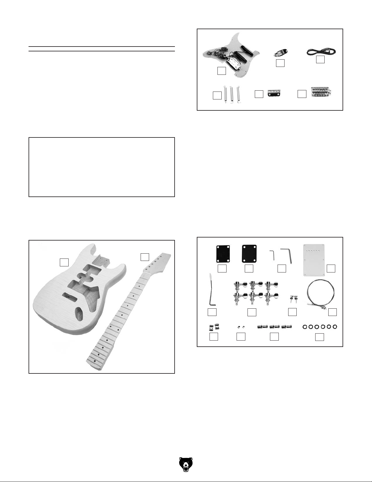
This instrument was carefully packaged for safe
transport. When unpacking, separate all enclosed
items from packaging materials and inspect them
for shipping damage. If items are damaged,
please call us immediately at (570) 546-9663.
IMPORTANT: Save all packaging materials until
your are completely satisfied with the instrument
and have resolved any issues between Grizzly or
the shipping agent. You must have the original
packaging to file a freight claim. It is also extreme-
ly helpful if you need to return your instrument.
Planning &
Preparation
Total time building this instrument will vary on
many factors. Variables such as glue manufactur-
er's instructions and curing time, temperature and
humidity at the time of building, and your schedule
are just a few of the factors that can affect the
length of time spent on this project.
Perhaps the biggest determinant of time spent
completing this instrument will be the type of fin-
ish and the finishing process used. Finishing this
instrument can be as simple as applying a single
coat of stain or lacquer that can be done rela-
tively quickly, up to a multi-coated finish that takes
weeks to harden.
Careful planning and budgeting ample time will
make this project easier and ensure you end up
pleased with your results. Good luck building your
instrument, and Grizzly hopes it turns out looking,
and sounding great.
Wear safety glasses during
the entire setup process!

-6- Model T33955 T33956 (Mfd. Since 09/23)
Inventory
The following is a list of items shipped with your
instrument. Before beginning assembly, lay these
items out and inventory them.
If any non-proprietary parts are missing (e.g.
strings, or tuning machine screws), we will gladly
replace them; or for the sake of expediency,
replacements can be obtained at your local music
shop.
Body and Neck (Figure 1) Qty
A. Body ........................................................... 1
B. Neck ........................................................... 1
Figure 1. Body and neck.
AB
Figure 2. Electrical components.
H
C
DE
FG
Guitar Components (Figure 3) Qty
I. Neck Plate .................................................. 1
J. Neck Plate Gasket...................................... 1
K. Hex Wrenches 1.5, 4mm ......................1 Ea.
L. Back Plate .................................................. 1
M. Tremolo Bar................................................ 1
N. Tuning Machines ........................................ 6
O. Strap Buttons.............................................. 2
P. String Set.................................................... 1
Q. String Retainers.......................................... 2
R. Bushings 4 x 5 x 3mm................................ 2
S. Tuning Machine Seats................................ 6
T. Tuning Machine Washers........................... 6
Figure 3. Guitar components.
T
I J K L
NOP
QS
M
R
NOTICE
If you cannot find an item on this list, care-
fully check around/inside the machine and
packaging materials. Often, these items get
lost in packaging materials while unpack-
ing or they are pre-installed at the factory.
Hardware (Not Shown):
U. Phillips Head Screws M2 x 14.................... 6
V. Phillips Head Screws M2.5 x 14................. 2
W. Phillips Head Screws M3 x 12.................. 27
X. Phillips Head Screws M3.5 x 25................. 2
Y. Phillips Head Screws M3.5 x 30 ................ 6
Z. Phillips Head Screws M4 x 50.................... 2
AA. Phillips Head Screws M5 x 45 ................... 4
Electrical Components (Figure 2)Qty
C. Pick Guard.................................................. 1
D. Output Jack ................................................ 1
E. Guitar Cable ............................................... 1
F. Tremolo Springs ......................................... 3
G. Spring Hanger ............................................ 1
H. Tremolo Bridge ........................................... 1

-7-
Model T33955 T33956 (Mfd. Since 09/23)
Body
SECTION 3: SANDING
Damage to your eyes and lungs could result
from dust created by sanding without proper
protective gear. Always wear safety glass-
es and a NIOSH-approved respirator when
sanding.
1. Sand body with #180-grit aluminum-oxide
sandpaper until there is a consistent scratch
pattern on entire surface.
Note: When hand sanding, always sand in
same direction as wood grain.
2. Repeat Step 1 with #240-grit sandpaper.
3. Repeat Step 1 with #320-grit sandpaper.
4. Wipe body with a damp, lint-free cloth. Wiping
workpiece with a damp cloth before final
sanding helps "raise" wood grain; thus allow-
ing "raised" grain to be sanded smooth.
5. Resand entire body with #320 sandpaper to
sand to "raised" grain smooth.
6. Wipe body with a tack cloth to remove all
remaining sanding dust.
To sand body:
The guitar body was assembled and rough sand-
ed at the factory; however, no finish has been
applied. The joint cavity where the neck meets the
body and the electronic component holes should
NOT be sanded.
Like the guitar body, most of the guitar neck has
been machined and rough sanded at the factory;
however, the neck headstock can be customized
to reflect personal taste. Additional cutting, inlay,
or design work can give a guitar that personalized,
custom look that makes it unique.
Note: If you do choose to customize the neck area
take your time with this sub-section and consider
testing ideas on scrap wood before performing the
work on the actual headstock.
Neck
To sand neck:
1. Perform any custom cutting, inlay, or design
work to headstock.
2. Using sanding technique described in previ-
ous sub-section, sand entire guitar neck.
Note: DO NOT sand fretboard. Sanding
fretboard will affect playability of guitar and
could lead to irreparable damage.
Preparing to Finish
In preparation for applying the finish, cover the
fretboard, neck pocket, and guitar body cavities
with masking tape or painter's tape.
Carefully press all masking tape edges securely
to the guitar pieces. Finish can seep under
these edges, especially near corners and uneven
edges, and where frets meet the fretboard.
Note: Failure to properly mask these areas can
result in irreparable damage to the guitar.

-8- Model T33955 T33956 (Mfd. Since 09/23)
Painting/Finishing
Finishing supplies are not supplied with the guitar
kit.
There are many resources (books, videos, web-
sites) that discuss guitar finishing. Grizzly recom-
mends consulting these sources before finishing
your instrument.
Listed below are a few general tips that can be
helpful in finishing your instrument.
Painting/Finishing Tips:
• Always work in a well ventilated area when
using finishing materials.
• Wear an ANSI-approved respirator mask and
safety glasses when using finishing materials!
• Fabricate hooks from metal hangers to sus-
pend guitar components during finishing
process.
• Several thinner coats usually produce a nicer
finish than one heavy coat.
Note: Always follow finish manufacturer’s
instructions.
• Dust particles suspended in air will settle on
wet finishes, resulting in less than satisfacto-
ry results. To avoid this problem:
1. Have guitar components positioned for fin-
ish application upon entering room.
2. Leave room where finishing will take place
completely undisturbed for 24 hours prior
to applying finish.
3. Avoid making unnecessary movements
upon entering finish room.
4. Apply finish to desired guitar parts and
immediately leave finish room.
5. DO NOT return to room until specified dry-
ing time has elapsed.

-9-
Model T33955 T33956 (Mfd. Since 09/23)
SECTION 4: ASSEMBLY
Routing Wires 4. Place pick guard on guitar body as shown in
Figure 5,and temporarily secure with mask-
ing tape. Attached pickups should fit into
routed channels.
5. DO NOT install screws at this time! Final
adjustments will be made after installing
strings.
Figure 5. Pick guard placed on body.
Apply Masking Tape
to These Areas
Before proceeding with the assembly, three wires
must be routed from the volume control poten-
tiometer on the back of the pick guard to their
proper places on the guitar body.
To route wires:
1. Lay pick guard face down on guitar body.
2. Push (1) black ground wire through hole
that leads to rear cavity in back of guitar, as
shown in Figure 4. This wire will be soldered
to spring hanger in later step.
3. Push (1) black wire and (1) yellow wire
through hole leading to output jack cavity
shown in Figure 4.These will be soldered to
output jack in later step.
Figure 4. Wires correctly routed.
Output Jack
Cavity
To Rear
Cavity

-10- Model T33955 T33956 (Mfd. Since 09/23)
Installing Neck
Unless otherwise indicated, we strongly recom-
mend using a drill press for the majority of drilling
to obtain the most precise results. However, an
electric/cordless drill fitted with a depth stop or a
drill stand can be used if you do not have a drill
press.
We recommend using a hollow punch to carve
out holes in the finish before drilling. Also, a router
pad placed under the guitar can help reduce
scratches on the finish.
To mount neck:
1. Insert neck into neck pocket (see Figure 6),
and check to make sure neck and body are
flush.
— If there is a gap between neck and body,
lightly sand high points on neck until it fits
in pocket.
2. Using a C-clamp, press neck and body
together.
3. Set guitar facedown on top of several 2x4's
(cut to 6" or 12") for support.
Figure 7. Making a pilot hole in neck.
4. Insert a 5⁄32" drill bit by hand into each pre-
drilled neck hole (see Figure 7). While press-
ing down slightly, twist drill bit to make pilot
holes in neck.
Neck Mounting
Hole (1 of 4)
Figure 6. Example of mounting neck.
Neck
Pocket
5. Place neck plate and neck plate gasket on
top of body so a mounting hole extends
beyond body and neck (see Figure 8).
6. Insert (1) M5 x 45 Phillips head screw through
plate and gasket (see Figure 8).
7. Gently mark screw tip depth on neck with a
pencil (see Figure 8).
Note: You may want to cover screw tip
marking location with masking tape to avoid
scratching finish.
Figure 8. Depth of screw tip marked on neck.

-11-
Model T33955 T33956 (Mfd. Since 09/23)
8. Set neck face down on drill press table, lower
bit to touch mark made in Step 4, then adjust
drill press to stop at this mark.
9. Lower 5⁄32"drill bit over center of pilot holes
and drill holes to correct depth.
10. Place neck plate on body.
Note: DO NOT glue neck to body.
11. Align mounting holes in neck, body, neck plate,
and neck plate gasket.
12. Secure neck with (4) M5 x 45 Phillips head
screws (see Figure 9).
Note: Shims may need to be placed between
neck and neck pocket to ensure proper
height of fretboard upon installation if neck
and fretboard are not even.
Installing
Tremolo Bridge
To attach tremolo bridge:
1. Place tremolo bridge in cut-out shown in
Figure 10.
Figure 10. Example of tremolo bridge placement.
Tremolo
Bridge
Tremolo Arm
Location
2. Test fit tremolo bridge and use a pencil to
mark location of mounting holes.
3. Use
1⁄16" drill bit to pre-drill marked holes.
4. Secure tremolo bridge to guitar body with (6)
M3.5 x 30 Phillips head screws.
5. Turn guitar body over and place spring hang-
er in cavity, as shown in Figure 11.
Figure 11. Spring hanger placement.
Spring
Hanger
Ground
Wire
Ground Wire
Solder Point
Figure 9. Mounting neck to body.
x 4
The tremolo bridge is used to change the pitch of
the strings on the guitar.

-12- Model T33955 T33956 (Mfd. Since 09/23)
6. Secure spring hanger to guitar body with (2)
M4 x 50 Phillips head screws, as shown in
Figure 12. Tighten screws until spring hanger
is 1" from wall of cavity.
7. Clean a spot on top of spring hanger to
remove grease and dirt, then solder black
ground wire from Step 2 on Page 9 to spring
hanger, as shown in Figure 12.
8. Stretch three springs from spring hanger to
tremolo bridge, as shown in Figure 12.
Installing
Output Jack
— If springs are too loose and will not grasp
spring hanger, tighten screws to move
hanger closer to body.
9. Turn guitar face up and ensure that tremelo
bridge is sitting flat on face of guitar. Loosen
or tighten screws until tremelo sits perfectly
flat.
10. Screw tremolo arm into tremolo arm socket,
as shown in Figure 14.
To attach output jack:
1. Solder (1) black wire and (1) yellow wire from
Step 3 on Page 9 to tabs on output jack, as
shown in Figure 13.
2. Insert output jack assembly into cavity on
guitar body and secure with masking tape.
3. Use a 3⁄32" drill bit to drill two 3⁄8" deep holes
through holes in output jack.
4. Secure output jack to guitar body with (2) M
3
x 12 Phillips head
screws (see Figure 14).
The output jack transfers the signal from the
guitar to the instrument cable and amplifier to
produce sound.
Figure 12. Springs and spring hanger installed,
and ground wire soldered to hanger.
1"
Ground
Wire Solder
Point
x 2
Spring
(1 of 3)
Figure 13. Wires soldered to output jack tabs.
Solder
Points
Figure 14. Output jack and tremolo arm
installed.
x 2
Tremolo
Arm
Socket
Tremolo
Arm

-13-
Model T33955 T33956 (Mfd. Since 09/23)
Installing
Strap Buttons
The strap buttons are positioned on the guitar, as
shown in Figure 15.
To install strap buttons:
1. Use a 3/32" drill bit to drill 1/2" deep holes at
locations shown in Figure 15.
2. Use (2) Phillips head screws provided with
strap buttons to secure each button to guitar
body (see Figure 15).
Installing Back Plate
To simplify installing and removing the strings, the
slots in the back plate must align with the string
holes in the bottom of the tremolo bridge.
To install back plate:
1. Turn guitar face down, position back plate
over cavity in back of guitar body, as shown
in Figure 16.
Note: Make sure slots in back plate are cen-
tered over tremolo string holes.
2. Secure position of back plate to guitar body
with masking tape.
3. Use a 3⁄32" drill bit to drill 5⁄16" deep holes
straight through six holes in back plate.
4. Remove protective plastic film from back
plate.
5. Secure back plate to guitar body with (6) M3
x 12 Phillips head screws, and remove mask-
ing tape (see Figure 16).
Figure 16. Correct position of back plate.
x 6
Figure 15. Strap button placement.
x 2
Strap Button
(1 of 2)

-14- Model T33955 T33956 (Mfd. Since 09/23)
Installing
Tuning Machines
The supplied tuning machines are easily installed.
Each tuning machine consists of the parts shown
in Figure 17.
3. Secure tuning machines to headstock with
screws, as shown in Figure 18.
Note: Use a straightedge to make sure tun-
ers are aligned. Adjust if necessary.
To install tuning machines:
1. Using a non-marring mallet, tap each of (6)
machine seats and washers into pre-drilled
holes on front of headstock.
2. From back of headstock, slide posts through
headstock and secure in seats (see Figure
17).
Note: Position tuning machine buttons away
from headstock.
Tuning Machine Seat
Tuning Machine
Washer
Tuning Machine Post
Tuning
Machine
Screw
Headstock
Tuning Machine
Button
Figure 17. Tuning machine components.
Figure 18. Tuning machines installed and
aligned on headstock.
x 6
Ensure
Tuners are
Aligned

-15-
Model T33955 T33956 (Mfd. Since 09/23)
To install nut:
1. Use a hobby knife or razor blade to scrape
any finish out of nut slot (see Figure 19). DO
NOT remove any wood from nut slot.
Note: Curved part of nut should face head-
stock.
3. Remove nut, spread a thin layer of glue in
nut slot, and install nut in slot, ensuring it is
centered from side to side.
4. Clamp nut in place.
5. Wipe away excess glue with a damp cloth,
and allow glue to dry for 24 hours.
Figure 19. Nut installed.
Large
Grooves
Nut
Installing Nut
The nut is located at the top of the fretboard and
holds the strings in place. The nut can be held in
place with string tension, or it can be spot glued
in place for more security.
If you prefer to glue, we recommend using wood
glue so that future adjustments can be made. For
a more permanent bond, super glue can be used,
but future adjustments will be more difficult.
ALWAYS follow the adhesive manufactur-
er's instructions for your safety and best
results.
2. Test fit nut in slot, ensuring large grooves
face toward top of neck, as shown in Figure
19.
— If nut fits snugly in slot, proceed to Step 3.
— If nut does not fit in slot, sand one side on
a piece of sandpaper until it fits snugly in
slot.

-16- Model T33955 T33956 (Mfd. Since 09/23)
Installing Strings
The correct position of the guitar strings is shown
in Figure 20. The thin High "E" string is the "1st"
string, and the thick Low "E" string is the "6th."
To install strings:
1. Slide 1st string through corresponding hole in
tremolo bridge (see Figure 21).
2. Guide string through tremolo bridge, across
saddle (see Figure 21), over nut, and through
hole in corresponding tuning machine
(see Figure 22).
Figure 20. Correct string locations.
D
E
E
A
D
G
B
6
1
5
4
3
2
Figure 22. String installed in tuning machines.
3. Allow only enough slack in string for 2–3 rota-
tions around tuning machine post.
Note: If too much slack is allowed, then string
could wind off tuning machine post after
many successive rotations. If not enough
slack is allowed, then string may not hold
winding tension.
4. Bend string at a right angle across edge of
tuning machine post.
5. Rotate tuning machine until string just begins
to hold winding tension (see Figure 23), and
so string is on right side of tuning machine
post.
Note: DO NOT tighten strings beyond initial
tensioning at this time. Final tensioning will
be completed during string tuning process.
6. Use wire cutters to cut off excess string.
7. Repeat above process for remaining strings.
Tuning
Machine
Post
To
Neck
Figure 23. String wrapped around tuning
machine post.
Figure 21. Example of 1st string installed.
1st String
Saddle
2nd 1st
3rd4th5th6th

-17-
Model T33955 T33956 (Mfd. Since 09/23)
Installing Pick Guard Installing
String Retainers
The string retainers mount between the 1st and
2nd strings, and between the 3rd and 4th strings
(see Figure 25). String retainers are designed to
hold the strings down against the nut to enable
correct tuning.
To install string retainers:
1. Place 1st string retainer on top of 1st and 2nd
strings near second tuner and loosen strings
several turns.
2. Using a 1⁄16" drill bit positioned through string
retainer, drill a 1⁄4" deep hole into headstock.
Note: Drilling hole deeper than 1⁄2" could
result in drilling through bottom of headstock.
3. Slide screw provided with retainer through
retainer and bushing, then fasten it to head-
stock (see Figure 25).
4. Place 2nd string retainer on top of 3rd
and 4th strings, loosen strings, and repeat
Steps 2–3.
To install pick guard:
1. Use a 3⁄32" drill bit to drill 5⁄16" deep holes
through eleven holes in pick guard (see
Figure 24).
2. Remove protective plastic film from pick
guard.
3. Secure pick guard to guitar body with (19) M3
x 12 Phillips head screws (see Figure 24).
Figure 24. Pick guard installed on body.
4. Remove masking tape.
x 12
Now that the electronics components have been
installed, the pick guard can be permanently
installed.
Figure 25. String retainer locations.
x 2
2nd Retainer
1st Retainer

-18- Model T33955 T33956 (Mfd. Since 09/23)
SECTION 5: FINAL ADJUSTMENTS
— If neck is bowed less than 0.012", no
adjustment is necessary. Proceed to
Adjusting String Height on Page 19.
— If neck is bowed more than 0.012", pro-
ceed to Step 4.
4. Loosen strings so there is no tension on
neck.
5. Locate truss rod nut at bottom of headstock
(see Figure 26) and turn counterclockwise to
release tension on neck. Now tighten nut until
it just begins to grab.
— To flatten a down bow, turn truss rod nut
a 1⁄4turn clockwise. To correct an up bow,
turn nut a 1⁄4turn counterclockwise.
6. Tighten strings to playing tension, and check
neck with straightedge.
— If neck is correctly adjusted, go to
Adjusting String Height on Page 19.
— If neck is still out of adjustment, repeat
Steps 4–5.
Figure 26. Location of truss rod nut.
Truss
Rod
Nut
Guitar setup is an art that requires skill, patience,
and experience. If you have the patience, you can
acquire the skill and experience. If you don't have
the patience, you may want to have your guitar set
up by a qualified guitar technician.
This section presents an overview of setup prac-
tices. We highly recommended that you research
more in-depth methods. Books on setting up
electric guitars can be ordered through Grizzly
Industrial, luthier supply catalogs, or may be avail-
able through your local library.
General
The guitar neck was adjusted perfectly straight
before it was packaged. However, the moisture
content of wood acclimates to the humidity of the
surrounding environment, and this can result in
wood movement that affects alignment. The neck
may require adjustment several times a year,
particularly in regions where the seasonal climate
changes are more drastic.
Adjusting Neck
Tools Needed
Hex Wrench 4mm.............................................. 1
Straightedge ...................................................... 1
Feeler Gauge..................................................... 1
To adjust neck:
1. DISCONNECT GUITAR FROM AMP!
2. Tighten strings to playing tension.
3. Place a straightedge on fretboard, stretch-
ing from 1st fret to 17th. Measure any gaps
between straightedge and frets with feeler
gauge.
This manual suits for next models
1
Table of contents
Other Grizzly Musical Instrument manuals

Grizzly
Grizzly H8068 User manual

Grizzly
Grizzly H3123 User manual

Grizzly
Grizzly H3099 User manual

Grizzly
Grizzly H7582 User manual

Grizzly
Grizzly H7580 User manual

Grizzly
Grizzly H7582 Technical manual

Grizzly
Grizzly H8067 User manual

Grizzly
Grizzly H5966 User manual

Grizzly
Grizzly T23750 User manual

Grizzly
Grizzly H8066 User manual