4
E
Campo de aplicación
Es posible el funcionamiento con:
• Acumuladores a presión
• Calentadores instantáneos con control térmico/hidráulico
No es posible el funcionamiento con acumuladores
sin presión (calentadores de agua sin presión).
Aplicación para:
• Instalación de bañera/Instalación de ducha/Instalación central
Todos los termostatos se ajustan en fábrica a una presión
de trabajo de 3 bares en ambas acometidas.
Cuando se utiliza este modelo como termostato central,
se pueden instalar mezcladores en los puntos de consumo.
En este caso, la batería termostática suministra agua caliente
a la que se puede mezclar agua fría.
Solamente es necesaria una llave de paso adicional cuando
se conecten otras tomas de agua mediante salidas libres.
Datos técnicos
• Presión de trabajo
- Presión mínima de trabajo sin
resistencias postacopladas 0,5 bares
- Presión mínima de trabajo con
resistencias postacopladas 1 bar
- Recomendado 1 - 5 bares
• Presión de utilización máx. 10 bares
• Presión de verificación 16 bares
Si la presión en reposo es superior a 5 bares,
hay que instalar un reductor de presión.
¡Deberán evitarse diferencias de presión importantes
entre las acometidas del agua fría y del agua caliente!
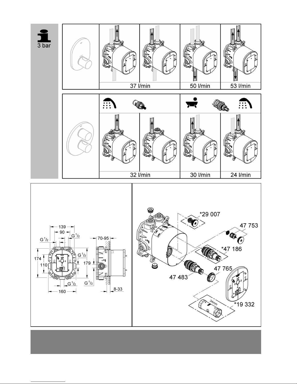
• Caudal para una presión de trabajo de 3 bares
(en caso de utilización simultánea
de todas las salidas) aprox. 53 l/min
Puntos a tener en cuenta durante la instalación
del desagüe
• Caudal mínimo 5 l/min
• Temperatura:
Entrada del agua caliente máx. 80 °C
Recomendada para ahorrar energía 60 °C
• Cierre de seguridad 38 °C
• Temperatura del agua caliente en la acometida mín. 2 °C
superior a la temperatura del agua mezclada
Atención en caso de peligro de helada
Al vaciar la instalación de la casa los termostatos deberán
vaciarse aparte, pues en las acometidas del agua fría y del agua
caliente hay válvulas antirretorno. Deberán desenroscarse todos
los componentes de los termostatos junto con las válvulas
antirretorno.
Nota:
En caso de una combinación de baterías empotrables y juegos
para llenado y rebose de bañeras, tenga en cuenta lo siguiente:
• Según la normativa EN1717 es necesario disponer de un
dispositivo de seguridad autorizado. Para ello se puede utilizar
un accesorio especial (véase Piezas de recambio en la página
desplegable I, núm. de pedido: 29 007).
• El dispositivo de seguridad debe montarse sobre el borde de la
bañera.
Instalación
Montaje,véase la página desplegable II, fig. [1].
Respetar el croquis de la página desplegable I.
Diferentes posibilidades de montaje, véanse los orificios
de fijación previstos en la fig. [1].
Al instalar un sistema GROHE Custom Shower, hay que tender
una línea de alineamiento a la altura de la marca (véase el
detalle (B1)) para otras cajas de instalación.
Hacer los agujeros para los termostatos así como las rozas
para las tuberías.
Montar el termostato con ayuda de la plantilla de montaje,
véanse las figs. [2] y [3].
• La superficie de pared acabada debe encontrarse
en la zona (A) de la plantilla de montaje.
• La acometida del agua caliente debe estar a la izquierda;
la acometida del agua fría debe estar a la derecha.
Alinear el termostato,véase la fig. [1].
Colocar un nivel de burbuja en los tetones (B) del patrón
de montaje.
Conectar las tuberías,véanse las figs. [2] y [3].
• En caso del montaje como batería de bañera, deberá
enroscarse herméticamente uno de los tapones adjuntos (C)
en la salida que queda libre (abajo), véase la fig. [2].
• En caso del montaje como batería de ducha, deberán
enroscarse herméticamente los tapones adjuntos (C) en las
salidas que quedan libres (arriba y abajo), véase la fig. [2].
• En caso del montaje como batería central, deberán enroscarse
herméticamente los tapones adjuntos (C) en las salidas que
quedan libres (arriba), véase la fig. [3].
La salida inferior siempre requiere de una llave
de paso adicional.
No es posible realizar una conexión por soldadura,
pues ésta podría dañar las válvulas antirretorno.
¡Abrir las llaves de paso del agua fría y del agua
caliente y comprobar la estanqueidad de las conexiones
de la grifería!
Rapido T en combinación con juego para llenado y rebose
de bañeras, véanse las figs. [4] a [6].
Durante la instalación, cerrar las tuberías de agua hacia el juego
para llenado y rebose de bañeras mediante el tapón (F) adjunto:
1. Extraer la tapa (D), véase la fig. [4].
2. Desenroscar el tapón roscado (E).
3. Colocar el tapón (F) en la salida del juego para llenado
y rebose de bañeras, véase la fig. [5].
4. Enroscar el tapón roscado (E), véase la fig. [6].
5. Montar la tapa (D).
Nota:
Durante el montaje de las instalaciones de acabado
deberá quitarse el tapón (F).
¡Purgar a fondo el sistema de tuberías antes y después de la
instalación (tener en cuenta EN 806), véanse las figs. [7] y [8].
1. Extraer la tapa (D), véase la fig. [7].
2. Cerrar las llaves de paso del agua fría y del agua caliente.
3. Desenroscar el tapón roscado (G).
4. Extraer la válvula antirretorno (H) y el tamiz (I).
5. Enroscar los tapones de purga (J) en el asiento libre
de la válvula antirretorno, véase la fig. [8].
6. Abrir las llaves de paso del agua fría y del agua caliente
y purgar a fondo las tuberías.
7. Cerrar las llaves de paso del agua fría y del agua caliente
y quitar los tapones de purga (J).
8. Colocar el tamiz (I) y la válvula antirretorno (H),
véase la fig.[7].
9. Enroscar el tapón roscado (G).
10. Abrir las llaves de paso del agua fría y del agua caliente.
Montar el material de base para el impermeabilizante,
véanse las figs. [9] y [10].
1. Aplicar el impermeabilizante o el adhesivo, véase la fig. [9].
2. Separar la parte central (K1) del material de base (K)
por las almas (K2).
3. Desplazar el material de base (K) sobre la plantilla de montaje.
4. Aplicar nuevamente el impermeabilizante o el adhesivo,
véase la fig. [10].
Enlucir por completo la pared y alicatarla, véase la fig. [11].
No acortar la plantilla de montaje antes de proceder
a la instalación de acabado.
Piezas de recambio,véase la página desplegable I
(* = accesorios especiales).