2
GB
Installation
- Plaster and tile the wall, excluding the area occupied by the
mounting template. Seal any apertures in the wall so that they
are watertight to spray water.
x
Tiles laid in mortar should be pointed so that the joint is
tapered towards the outside.
x
Seal prefabricated walls with a permanently plastic compound.
- Remove the mounting template, see fold-out page I fig. [1].
- Install sleeve (C).
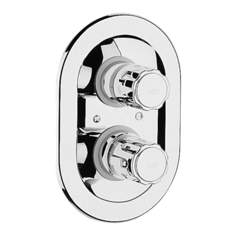
Installing the escutcheon with flow control knob,
see figs. [2], [3] and [4].
- Fit holder (E) with marking (E1) facing upwards and secure with
bush (G) with 19mm socket wrench, instal sleeve (F),
see fig. [2].
- Grease the seals (H) for the escutcheon mounting bracket (J)
with the special grease supplied and installescutcheon mounting
bracket (J) with mounting assembly (K), see fig. [3].
- Fit the escutcheon (L).
If the thermostat has been installed at too great a depth, this
can be adjusted by 27.5mm with an extension set (see fold-out
page II, ref. No. 47 654).
- Fit splined adapter (M), see fig. [4].
- Turn splined adapter (M) to the right (water discharge from the
bath spout) until it reaches the end stop.
Remove splined adapter (M) and fit again so that one of the
marks (M1) point upwards.
- Turn splined adapter (M) 180
q
to the left (2nd mark (M1) is at the
top, water stops flowing).
- Fit flow control knob (O) so that the button (O1) point upwards.
- Install snap insert (P) with screw (R).
- Fit knob (S).
In this process, take care to ensure that the shut-off function is
effective, after closing, in both the bath spout and shower outlet
positions.
Shut-off knob (O) operation.
Shut-off knob in central position = closed
Shut-off knob clockwise = discharge from spout
Shut-off knob anti-clockwise = discharge from shower
[Press button (O1)]
Adjustment
Installation of the thermostat knob and temperature
adjustment, see figs. [5] and [6].
x
Before the mixer is put into service if the mixed water
temperature measured at the point of discharge varies from the
specified temperature set on the thermostat.
x
After any maintenance operation on the thermoelement.
1. Open the shutt-off valve and check the temperature of the water
with a thermometer, see fig. [5].
2. Turn the adjusting nut (A) clockwise or anticlockwise until the
water temperature reaches 38
q
C.
3. Install temperature control handle (T) in such a way that the 38°
mark point upwards, see fig. [6].
4. Fit snap insert (U) and install with screw (V).
5. Fit knob (W).
Reversed union (hot on right - cold on left).
Replace thermoelement (X), see replacement parts fold-out page II,
ref. No. 47 658 (3/4”).
The stop ring (D) is not used by using the concealed mixer
housing 34 103.
Temperature limitation
The safety stop limits the temperature range to 38
q
C.
If a higher temperature is desired, the 38
q
C limit can be overridden
by pressing the button (T1).
Prevention of frost damage
When the domestic water system is drained, thermostat mixers
must be drained separately, since non-return valves are installed in
the hot and cold water connections.
The complete thermostat assemblies and non-return valves must
be unscrewed and removed.
Maintenance
For maintenance, see fold-out page II and III, figs. [7], [8] and [9].
Inspect and clean all parts, replace if necessary and grease with
special valve grease (ref. No. 18 012).
Shut off cold and hot water supplies.
I. Thermoelement, see fold-out page III, fig. [7].
1. Pull off knob (W).
2. Unscrew screw (V) and pull off snap insert (U).
3. Pull off temperature control handle (T).
4. Remove clip (B1).
5. Pull off stop ring (B).
6. Remove adjusting nut (A) with overload unit (A1).
7. Pull off sleeve (C).
8. With a 22mm open-ended spanner, unscrew and remove
thermoelement (X).
Reassemble in reverse order.
The overload unit (A1) (left-hand thread) must be screwedas far as
possible in the adjusting nut (A).
Observe the correct installation position of the stop ring (B).
Readjustment is necessary after every maintenance operation on
the thermoelement (see Adjustment).
II. Non-return valve, see fold-out page II and III.
1. Pull off knobs (S) and (W).
2. Unscrew screws (R) and (V), pull off snap inserts (P) and (U).
3. Pull off temperature control handle (T) and shut-off knob (O).
4. Detach escutcheon (L) see fig. [8].
5. Unscrew screws (K) and remove escutcheon mounting
bracket (J).
6. Unscrew and remove non-return valve (Y) with 8mm socket
spanner.
7. Remove non-return valve (Y1) and filter (Y2).
III. Aquadimmer, see fold-out page II and III.
1. Proceed as for maintenance of non-return valve, points 1 - 5.
2. Remove splined adapter (M).
3. Unscrew and remove bush (G) with 19mm socket wrench, pull
off sleeve (F) and holder (E).
4. Unscrew and remove aquadimmer (Z) with a 19mm key.
Reassemble in reverse order.
Observe the correct installation position!
In this connection, take care to ensure that the semicircular locating
flange (Z1) projecting from the aquadimmer unit coincides with the
recess of the housing, see fig. [9].
If necessary fix washer (Z2) with a little grease, see fold-out
page II.
Replacement parts, see fold-out page II (* = special accessories).
Care
For directions on the care of this fitting refer to the accompanying
Care Instructions.
