GroPoint 2625-N-T Series User manual

GroPoint™ Profile Multi Segment
Soil Moisture & Temperature
Profiling Probe
Models 2625-N-T-x, 2625-N-x, 2625-M-T-x, 2625-M-x
OPERATION MANUAL
March 2023
V1.1.3

2 | P a g e
Need Help? Email support@gropoint.com or visit www.gropoint.com/support
RIOT Technology Corp. | #220–10114 McDonald Park Rd | North Saanich V8L5X8, BC Canada | +1.250.412.6642
www.riotwireless.com | www.gropoint.com
All Rights Reserved ©2020, RIOT Technology Corp.
Table of Contents
Overview ........................................................................................................................... 4
Technology (TDT) .............................................................................................................. 4
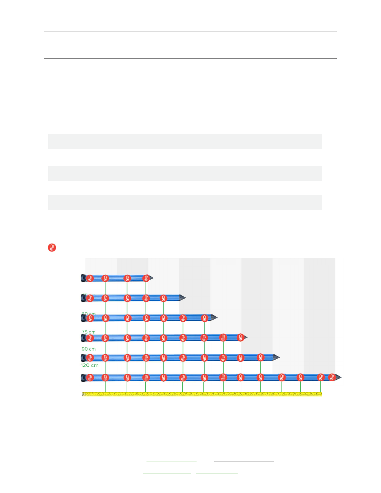
GroPoint™ Profile Model Variations ...................................................................................... 5
Probe Technology .............................................................................................................. 6
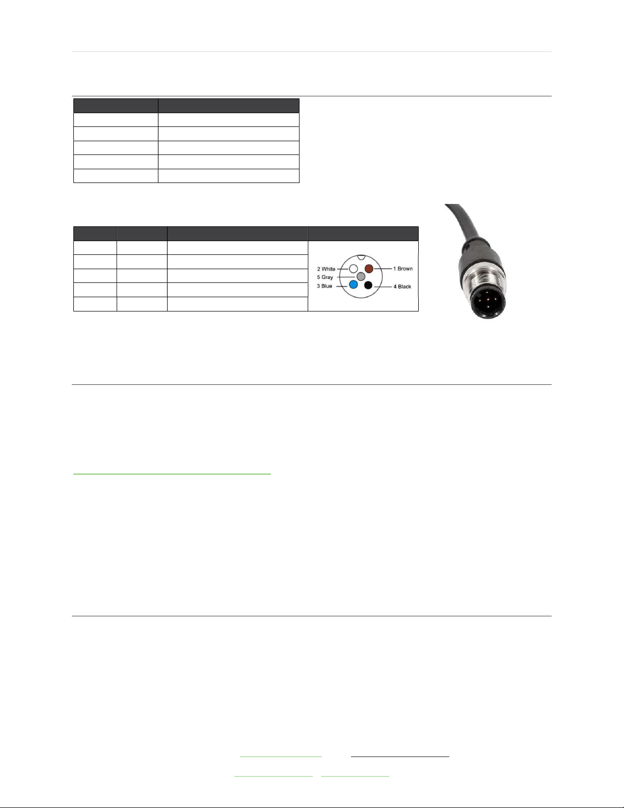
Wiring Connections ............................................................................................................ 7
Reading Methods ............................................................................................................... 7
Sensor Start Up Time / Measurement Time .......................................................................... 7
Important Things to Note ................................................................................................ 7
Basic SDI-12 Command List ................................................................................................ 8
How it Works ................................................................................................................. 8
Basic SDI-12 Command List ............................................................................................. 8
Understanding the Basic Commands .................................................................................... 8
Query Address Command: ?! ........................................................................................... 8
Acknowledge Active Command: a!.................................................................................... 9
Send Identification String Command: aI! .......................................................................... 9
Change Address Command: aAb! ..................................................................................... 9
Start Measurement Command: aM! or aM1! or aM2! .........................................................10
Start Concurrent Measurement Command: aC! .................................................................10
Send Data Command: aD0! or aD! ..................................................................................10
Extended SDI-12 Command List .........................................................................................11
Overview ......................................................................................................................11
Extended SDI-12 Command List ......................................................................................12
Extended Command Descriptions .......................................................................................13
Sensor Board Power Control: aXSc! .................................................................................13
Read/Write Operating Mode Setting: aXMn! .....................................................................13
Read/Write Coefficient/Scale Factor Setting: aXCn! ...........................................................13
Additional Product Information ...........................................................................................18
Specifications ................................................................................................................18
Ratings .........................................................................................................................18
Appendix A: Probe Installation / Extraction ..........................................................................19
Summary ......................................................................................................................19
Sensor Installation Guidelines .........................................................................................20

3 | P a g e
Need Help? Email support@gropoint.com or visit www.gropoint.com/support
RIOT Technology Corp. | #220–10114 McDonald Park Rd | North Saanich V8L5X8, BC Canada | +1.250.412.6642
www.riotwireless.com | www.gropoint.com
All Rights Reserved ©2020, RIOT Technology Corp.
Slide Hammer and Pilot Rod Installation Method ...............................................................21
Auger Installation Method...............................................................................................22
Excavation Installation Method ........................................................................................22
Removing the Sensor from the Soil .................................................................................22
Appendix B: Soil Specific Calibration Process .......................................................................23
Introduction ..................................................................................................................23
Overview ......................................................................................................................23
Equipment Required.......................................................................................................24
Procedure .....................................................................................................................25
Entering Coefficients into the Probe .................................................................................29
Appendix C: Determining Volumetric Moisture Content (Weight Method – In Laboratory) ........31
Procedure Overview .......................................................................................................31
Equipment Required.......................................................................................................31
Soil Sampling Ring Requirements ....................................................................................31
Sampling Ring calculation ...............................................................................................31
Sampling Method ...........................................................................................................31
Example Calculation .......................................................................................................34
Appendix D: Modbus Programming Manual .........................................................................35
Modbus Command Functions ..........................................................................................35
Data Values ...................................................................................................................37
GPLP Modbus Register Lists ............................................................................................37
Detailed Description of Holding Registers ......................................................................40
Coil Registers ................................................................................................................42
Discrete Inputs ..............................................................................................................42
Appendix E: Accessories ....................................................................................................43
Certificate of Compliance EU/Declaration of Conformity ........................................................44
About GroPoint™
...................................................................................................................45

4 | P a g e
Need Help? Email support@gropoint.com or visit www.gropoint.com/support
RIOT Technology Corp. | #220–10114 McDonald Park Rd | North Saanich V8L5X8, BC Canada | +1.250.412.6642
www.riotwireless.com | www.gropoint.com
All Rights Reserved ©2020, RIOT Technology Corp.
Overview
The highly accurate GroPoint™ Lite Multi-Segment Soil Moisture and Temperature Profiling
Probe (GPLP) provides cost effective soil moisture measurement over several depths using a
single probe, eliminating the need for multiple sensors placed at different depths and cumber-
some installations. GPLP can be deployed in irrigation sensitive zones, to enable full control of
precision irrigation needs, providing an understanding of water movement through the soil. Pro-
filing moisture measurement is ideal in a multitude of agricultural applications including vine-
yards, row crops, and orchards as well as silviculture and research to better manage irrigation
practices, increase plant/crop quality and yield, and reduce fertilizer run-off.
The sleek light weight design installs quickly with minimal soil disruption using a pilot rod and
slide hammer tool. Designed for vertical installation, the sensor takes measurements over multi-
ple soil layers, with each measurement zone providing the average volumetric soil moisture con-
tent over a 15 cm (6 inch) zone. The probe is attached to a 3-meter (9.8’) cable. Soil tempera-
ture measurements are also available.
Technology (TDT)
GroPoint™ sensors and probes use Time Domain Transmissometry (TDT) and patented tech-
nology as the basis for its measurement. The patented technology employs a unique antenna
design that enables extremely accurate and repeatable measurements while maintaining a
highly cost-efficient electronics and mechanical design. TDT measures the time taken for an
electromagnetic wave to propagate (travel) along a given length of a transmission line in the
soil. Moisture in the soil changes the soil’s dielectric properties, so that the electromagnetic
wave travels at different rates in wet soil compared to dry soil. This allows for the accurate de-
termination of the soil moisture content.
GroPoint™ TDT⁵ profiling probes detect water as much as 5 centimetres (2 inches) from the
surface of the probe fins although, like all dielectric based sensors, moisture closest to the sur-
face of the probe has more influence on the readings than moisture further away, so that soil
closely surrounding the sensor will have a greater influence on the soil moisture reading than
the soil further away.

5 | P a g e
Need Help? Email support@gropoint.com or visit www.gropoint.com/support
RIOT Technology Corp. | #220–10114 McDonald Park Rd | North Saanich V8L5X8, BC Canada | +1.250.412.6642
www.riotwireless.com | www.gropoint.com
All Rights Reserved ©2020, RIOT Technology Corp.
GroPoint™ Profile Model Variations
The GroPoint™ Profile sensor can be ordered with and without temperature sensors. The in-
formation in this manual covers material for sensors with temperature sensors. If you have or-
dered sensors without temperature sensors, the commands applicable to the temperature sen-
sor readings will be inactive. Model numbers of sensors are as follows:
Cable Connection: Either flying lead or M12 Connector, Interface: SDI-12, modbus or RS485 + SDI-12
Length & Number of Segments Part No. With Temperature Part No. Without
Temperature
2 Segment (30 cm)
2625-N-T-2
2625-N-2
3 Segment (45 cm)
2625-N-T-3
2625-N-3
4 Segment (60 cm)
2625-N-T-4
2625-N-4
5 Segment (75 cm)
2625-N-T-5
2625-N-5
6 Segment (90 cm)
2625-N-T-6
2625-N-6
8 Segment ( 120 cm)
2625-N-T-8
2625-N-8
= temperature sensor placement
2
30 cm
3
45 cm
4
60 cm
5
75 cm
6
90 cm
8
120 cm
Segment 3 Segment 1 Segment 8
Segment 7
Segment 6
Segment 5
Segment 4 Segment 2

6 | P a g e
Need Help? Email support@gropoint.com or visit www.gropoint.com/support
RIOT Technology Corp. | #220–10114 McDonald Park Rd | North Saanich V8L5X8, BC Canada | +1.250.412.6642
www.riotwireless.com | www.gropoint.com
All Rights Reserved ©2020, RIOT Technology Corp.
Probe Technology
The drawing below shows the probe dimensions of the 2-8 segment probes, Temperature sen-
sor locations provided in table below:

7 | P a g e
Need Help? Email support@gropoint.com or visit www.gropoint.com/support
RIOT Technology Corp. | #220–10114 McDonald Park Rd | North Saanich V8L5X8, BC Canada | +1.250.412.6642
www.riotwireless.com | www.gropoint.com
All Rights Reserved ©2020, RIOT Technology Corp.
Wiring Connections
Wire Colour Function
Brown + Power (6.5V-18VDC)
White
MODBUS/RS485 D
-
Blue
MODBUS/RS485 D+
Black SDI-12 I/O
Gray Ground
*Standard cable wire colours. Other cable options available (may have different colours)
Optional M12 5-Pin Male A-Code Connector
Pin #
Colour
Function Pin Locations
1
Brown
+ Power (6.5V
-
18VDC)
2
White
MODBUS/RS485 D
-
3 Blue MODBUS/RS485 D+
4 Black SDI-12 I/O
5 Gray Ground
*Available as field installable option, with screw terminal wire
termination.
Reading Methods
The GPLP Lite multi-segment soil moisture profiling probes use the SDI-12 Protocol for serial
communications. The sensors conform to V1.3 of the SDI-12 protocol. Serial communication
settings are 1200 baud, 7 data bits, even parity, 1 stop bit. SDI-12 commands must begin with
a minimum 12.5 ms break signal, followed by an 8.3 ms mark space, then the command char-
acters. Note: for a complete description of the SDI-12 communications protocol, please refer to
http://www.sdi-12.org/specification.php
GroPoint™ Profile probes may be read with any compatible SDI-12, Modbus or RS485 logger,
communications interface, or reader unit. (RIOT offer accessories for reading SDI-12 sensors:
the GroPoint™ GP-DU SDI-12 Display Unit (Part# 2628) is a handheld display unit for
taking field readings; the GroPoint™ GP-USB Connect - SDI-12 Sensor (Part# 6300) is a
USB to Sensor interface that connects sensors directly to application software on a USB
equipped computer. GroPoint™ accessories are listed in appendix E of this manual.
Sensor Start Up Time / Measurement Time
Important Things to Note
The time from application of power to the SDI-12 power bus until the sensor is ready to receive
a command is approximately 350 ms. The reported measurement time in response to the M!
measure command (where “a” is sensor address) is 002 seconds. Actual measurement time is
approximately 100ms per segment, so the three-segment probe measurement will typically be
less than one second from the end of the aM! command response (a0021<CR><LF>) until the
measurement finished service request (a<CR><LF>). Power current consumption is at an

8 | P a g e
Need Help? Email support@gropoint.com or visit www.gropoint.com/support
RIOT Technology Corp. | #220–10114 McDonald Park Rd | North Saanich V8L5X8, BC Canada | +1.250.412.6642
www.riotwireless.com | www.gropoint.com
All Rights Reserved ©2020, RIOT Technology Corp.
active level (about 15-20 mA) only during measurement time, otherwise current is usually less
than 0.5 mA.
Basic SDI-12 Command List
How it Works
Following is a list of the supported commands for the sensor. In the descriptions below, SDI-12
command/response sequences are show in Courier font, with a box surrounding the text. The
command from the SDI-12 Logger/Recorder is shown in bold text. The response from the sen-
sor is shown in normal text. As is normal, SDI-12 commands are always terminated with the ‘!’
character. Responses from the sensor always include the sensor’s address as the first character
and are always terminated with the <CR><LF> (carriage return-line feed) sequence.
Basic SDI-12 Command List
The GroPoint™ Lite Profiling Probes respond to the following basic SDI-12 commands. In all
cases,
a
= sensor address. Default sensor address is ‘0’.
Command Meaning Response
?!
Address Query Device address (default address is ‘0’)
a
!
Acknowledge
Device address (default
address is ‘0’)
a
I! Send Identification Identification string
a
A
b
!
Change Address
Change device address to ‘b’
a
M!
aM1!, aM2!
Start Moisture Measurement
Start Temp. Measurement
Measure time and count (e.g. “a0023”)
a
C!
aC1!, aC2!
Start Concurrent Measurement Measure time and count (e.g. “a00023”)
a
D0!
aD1!*
Send Data Measurement values
* Necessary for GPLP-8 only, for segment 7 and 8 measurement values
All other commands received by the sensor will be acknowledged with the device address only.
Understanding the Basic Commands
Query Address Command: ?!
Use this command to query a sensor for its address. This will allow a user to determine the ad-
dress of a sensor if it is unknown. Please understand that if more than one sensor is connected
to the SDI-12 communication bus, they will all respond to this command, causing a bus conten-
tion, and usually a garbled response.

9 | P a g e
Need Help? Email support@gropoint.com or visit www.gropoint.com/support
RIOT Technology Corp. | #220–10114 McDonald Park Rd | North Saanich V8L5X8, BC Canada | +1.250.412.6642
www.riotwireless.com | www.gropoint.com
All Rights Reserved ©2020, RIOT Technology Corp.
For example, for a sensor with address ‘0’ (default address), the command/response sequence
is as follows:
?!0<CR><LF>
Acknowledge Active Command: a!
Use this command to ensure that a sensor is responding to a data recorder or other SDI-12 de-
vice. The command consists of the sensor’s address and the ‘!’ command termination character.
When this command is received by the sensor with matching address, it responds with its ad-
dress, followed by the <CR><LF> sequence.
For example, for a sensor with address ‘0’ (the default address), the command/response se-
quence is as follows:
0!0<CR><LF>
Send Identification String Command: aI!
Use this command to query the sensor for its SDI-12 compatibility level, vendor, model number,
and firmware version number. The command consists of the sensor’s address, the ‘I’ character,
and the ‘!’ command termination character.
For example, the response, for a sensor with address ‘0’ (the default address), is as follows:
0I!013RIOTTECHGPLPTN027SN300123<CR><LF>
This ID string identifies the supported SDI-12 compatibility level as 1.3, sensor vendor as
‘RIOTTECH’ (RIOT Technology Corp.), the sensor model as GPLPTN (GroPoint™ Lite Profiling
with soil temperature), the firmware version as ‘027’ (V2.7 firmware), and the sensor’s serial
number as 300123.
Change Address Command: aAb!
Use this command to change a sensor with address ‘a’ to new address ‘b’. The factory default
address for all sensors is the ‘0’ character. If there will be more than one sensor on the SDI-12
communication bus, they must all have a unique address. ASCII '0' through ASCII '9' are the
standard addresses. Should there be a need for more than 10 sensors, you can also use an ad-
dress in the range ASCII 'A' through ASCII 'Z' and ASCII 'a' through ASCII 'z'. The sensor re-
sponds with the new address, and the <CR><LF> sequence.
For example, the following command/response sequence changes a sensor with address ‘0’ to
address ‘5’:

10 | P a g e
Need Help? Email support@gropoint.com or visit www.gropoint.com/support
RIOT Technology Corp. | #220–10114 McDonald Park Rd | North Saanich V8L5X8, BC Canada | +1.250.412.6642
www.riotwireless.com | www.gropoint.com
All Rights Reserved ©2020, RIOT Technology Corp.
0A5!5<CR><LF>
Start Measurement Command: aM! or aM1! or aM2!
Use this command to start a sensor measurement. Use M! to start the soil moisture measure-
ments. Use M1! and M2! (6 or 8 segment probes only) to start the temperature measure-
ments. See specification sheet provided with sensor for more details. The sensor responds with
its address, and a string of numbers (e.g. ‘0024’) which represents the expected time in sec-
onds until the measurements will be ready (‘002’ seconds) and the number of measurements
that it will make (‘4’ measurements). The data recorder is then expected to wait (no other com-
mands may be sent) and monitor the SDI-12 communication bus up to the expected time, or
until the sensor responds with its address as a service request. The send data (D0!) command
can then be issued to get the measurements.
For example, sensors with address 0 and 1 respond as follows:
0M!00024<CR><LF> (sensor 0 will be ready in 002 seconds with 4 measurements)
0<CR><LF> (sensor 0 sends this when the measurement is complete)
1M!10024<CR><LF> (sensor 1 will be ready in 002 seconds with 4 measurements)
1<CR><LF> (sensor 1 sends this when the measurement is complete)
The actual measurement may take less than the expected time of 002 seconds. The service re-
quest will be sent by the sensors as soon as the measurement is complete, and data is ready.
Start Concurrent Measurement Command: aC!
Use this command to start a concurrent sensor measurement. The sensor responds with its ad-
dress, and ‘00204’ which represents the expected time in seconds until the measurements will
be ready (‘002’ seconds) and the number of measurements that it will make (‘04’ measure-
ments). The sensor begins the measurement process but does not send a service request on
completion. With a concurrent measurement command, the data recorder may send additional
commands to other devices while the sensor is busy taking measurements. Only after the ex-
pected measurement time has expired may the data recorder use the send data (aD0!) com-
mand to get the measurement data.
For example, sensors with address 0 and 1 respond as follows:
0C0!000204<CR><LF> (sensor 0 will be ready in 002 seconds with 04 measurements)
1C!100204<CR><LF> (sensor 1 will be ready in 002 seconds with 04 measurements)
Send Data Command: aD0! and aD1!
Use this command to instruct the sensor to return the measurement results. The sensor re-
sponds with its address, and the moisture values for each segment from top to bottom. Each
moisture value has the format ‘+mm.m’ which represents the volumetric moisture content in

11 | P a g e
Need Help? Email support@gropoint.com or visit www.gropoint.com/support
RIOT Technology Corp. | #220–10114 McDonald Park Rd | North Saanich V8L5X8, BC Canada | +1.250.412.6642
www.riotwireless.com | www.gropoint.com
All Rights Reserved ©2020, RIOT Technology Corp.
percent. The Send Data command “aD1!” is only necessary for eight-segment sensors, to return
the segment 7 and 8 measurement values.
For example, a GPLP-N-T-4 sensor (4 segments) with address 0 might respond as follows if the
measure command used was M!:
0D0!0+15.2+22.7+27.5+26.0<CR><LF>
If the previous Measure command was M1! (or M2! for 5, 6 and 8 segment probes), then the
sensor will return temperature readings in response to the D0! command. Refer to the table be-
low for temperature sensor locations. Temperature units are always in degrees Celsius (°C ).
For example, a GPLP-N-T-4 sensor with address 0 may respond as follows:
0D0!0+21.0+19.5+18.5+18.0+18.3+18.1+18.6<CR><LF>
aMi! Command Responses for Temperature Sensors:
Order Number
# Temp Cmd(s)
Response(s)
Sensor
Locations (from top)
GPLP-N-T-2 4 M1! a0024 3.5, 10, 20, 30
GPLP-N-T-3 6 M1! a0026 3.5, 10, 20, 30, 40, 45
GPLP-N-T-4 7 M1! a0027 3.5, 10, 20, 30, 40, 50, 60
GPLP-N-T-5 (2/3) 9 (7/2) M1!
M2!
a0027
a0022
3.5, 10, 20, 30, 40, 50, 60
70, 75
GPLP-N-T-6 (2/2/2) 10 (7/3) M1!
M2!
a0027
a0023
3.5, 10, 20, 30, 40, 50, 60
70, 80, 90
GPLP-M-T-6 (3/3) 11 (7/4) M1!
M2!
a0027
a0024
3.5, 10, 20, 30, 40, 50, 55
65, 75, 85, 90
GPLP-N-T-8 (2/2/2/2) 13 (7/6) M1!
M2!
a0027
a0026
3.5, 10, 20, 30, 40, 50, 60
70, 80, 90, 100, 110, 120
GPLP-M-T-8 (3/3/2) 14 (7/7) M1!
M2!
a0027
a0027
3.5, 10, 20, 30, 40,
50, 55
65, 75, 85, 95, 100, 110, 120
All measurement values for a given measurement command are returned on a single aD0! com-
mand response, except for eight-segment sensors. These require aD1! to return the soil mois-
ture values for segments 7 and 8.
Extended SDI-12 Command List
Overview
The extended SDI-12 commands are used to adjust the sensor settings and moisture calcula-
tion equation. Caution must be exercised when using the extended commands, as certain com-
binations of commands could render the sensor partially or completely inoperable or corrupt the
sensor’s base calibration.
Many of these commands require internal processing that delays the response from the sensor,
so strictly speaking they do not conform to certain timing requirement aspects of the SDI-12
protocol. This may require some timing adjustments in the communicating equipment, for ex-
ample extending the wait time when waiting for a response from the sensor after a command is

12 | P a g e
Need Help? Email support@gropoint.com or visit www.gropoint.com/support
RIOT Technology Corp. | #220–10114 McDonald Park Rd | North Saanich V8L5X8, BC Canada | +1.250.412.6642
www.riotwireless.com | www.gropoint.com
All Rights Reserved ©2020, RIOT Technology Corp.
sent. Most commands that write a new setting or coefficient value fall into this category. See
the specific commands for further information.
Special Notes Regarding Profiling Probes of 4 or More Segments
GPLP Lite Profiling probes with more than three segments have special requirements for com-
municating. Internally, these probes consist of several circuit boards daisy chained together: A
four-segment probe has two daisy chained 2-segment boards. A six-segment probe has two
daisy chained 3-segment boards. The first board ordinarily handles all normal communications,
particularly handling of all basic SDI-12 commands.
When necessary, there is a specific mechanism and requirements for sending commands di-
rectly to attached daisy chained boards and some special cautions must also be employed. In
particular:
Power to daisy chained boards is normally off and must be specifically turned on first
with the aXSA! command. A start up delay of at least 150 ms must occur after this
command before sending any further commands to the daisy chained board.
All measurement commands automatically turn off power to daisy chained boards to en-
sure the sensor returns to low power state, so if additional commands are to be sent af-
ter a measurement the aXSA! command must be resent to turn power back on.
Commands to a daisy chained board are embedded in the following special extended command
format:
aXn
command
!
where n is the position in the daisy chain. “1” is for the first attached board (segments 3 and 4
in a 4-segment probe), 2 is for the second attached board (usually only with 8-segment probes)
etc. The
command
can be any valid SDI- 12 command, including extended commands. Each
board in the chain includes its address in the response. For example, to get the ID string for the
first attached board (when the main sensor has address 0) send the command 0X1I! The re-
sponse will be something like “0013RIOTTECHGPLPT 027SN……”
Note that all subordinate/attached boards in a probe have a default address of 0, and this ad-
dress must NEVER be changed!
If you send the address change (aX0Ab!) command to an inter-
nally daisy chained board, this will render that board and all subsequent boards unresponsive
and inoperative.
Extended SDI-12 Command List
Command Meaning Response
aXSc! aA ON<CR><LF> for c=A
aOFF<CR><LF> for c=0
Enable power to daisy chained
board (GPLP-4, 5, 6 or 8)
aXM! aMode: n<CR><LF> read the current mode setting
aXMn! aMode: n<CR><LF> write the new mode setting to
n

13 | P a g e
Need Help? Email support@gropoint.com or visit www.gropoint.com/support
RIOT Technology Corp. | #220–10114 McDonald Park Rd | North Saanich V8L5X8, BC Canada | +1.250.412.6642
www.riotwireless.com | www.gropoint.com
All Rights Reserved ©2020, RIOT Technology Corp.
aXCn! aCoeff(n): cccccccc<CR><LF> read the coefficient n setting
aXCncccccccc!
aCoeff(n): cccccccc<CR><LF>
write the new coefficient n
value
Extended Command Descriptions
Sensor Board Power Control: aXSc!
This command is necessary when sending commands to daisy chained boards in probes of 4 or
more segments. Replace c with the character ‘0’ or ‘A’. Use c = ‘A’ to turn power on, use c = ‘0’
to turn power off. Note: Power is automatically turned off after any measurement command.
aXSc!
aA ON<CR><LF> or c=A
aOFF<CR><LF> for c=0
write the new power setting
Read/Write Operating Mode Setting: aXMn!
This command is used to adjust the operating mode of the sensor. The mode setting is non-
volatile, and only needs to be set once. Currently there are only two supported operating
modes, “0” and “1”:
Mode 0: Default Operating Mode, no special actions taken.
Mode 1: Enable application of third order polynomial to the measurement value.
Mode 1 allows the measured moisture value m to be recalculated by application of a third order
polynomial equation to the original measured value
m
. The new reported value
m’
is given by
the expression:
m' = A * m3 + B * m2 + C * m + D
The coefficient A, B, C and D are viewed and modified using the aXCn! Command (see below).
The default settings for these coefficients are 0, 0, 1, and 0 respectively so that m’ = m.
aXM! aMode: n<CR><LF> read the current mode setting
aXMn!
aMode: n<CR><LF>
write the new mode setting to n
In probes of 4 or more segments this command must also be issued to the daisy chained board
to change its operating mode. For example, for a sensor with address ‘0’ first issue 0XSA! to
enable power to the daisy chained board, then send the command 0X1XMn! where n is ‘0’ or
‘1’, as desired.
Read/Write Coefficient/Scale Factor Setting: aXCn!
This command is used to read or write the third order calibration coefficients used for calculat-
ing the moisture reading. All coefficients are non-volatile, and only need to be set once. Valid
values for n are the digits “0” to “9”, and the letters “A” to “C”. The value “cccccccc” is the

14 | P a g e
Need Help? Email support@gropoint.com or visit www.gropoint.com/support
RIOT Technology Corp. | #220–10114 McDonald Park Rd | North Saanich V8L5X8, BC Canada | +1.250.412.6642
www.riotwireless.com | www.gropoint.com
All Rights Reserved ©2020, RIOT Technology Corp.
coefficient setting, it must be exactly eight characters long. For explicit accuracy, these parame-
ters must be entered as the IEEE-754 hexadecimal representation of the decimal coefficient.
aXCn! aCoeff(n): cccccccc<CR><LF> read the coefficient n setting
aXCncccccccc! aCoeff(n): cccccccc<CR><LF> write the new coefficient n
value
For example, the number 0 is represented as “00000000”, 1.0000000 is represented as
“3F800000”, etc. RIOT provides on request a calibration program call GP Reader that makes the
necessary conversions from decimal values to IEEE-754 32-bit values and simplifies their entry.
Also, search "IEEE 754 calculator" for on-line conversion tools that can be used to generate the
hexadecimal values given a decimal number.
Coefficients are defined as follows, and are described in further detail below:
C(0): segment 1 scaling factor
C(1): coefficient A in 3rd order polynomial, segment 1
C(2): coefficient B in 3rd order polynomial, segment 1
C(3): coefficient C in 3rd order polynomial, segment 1
C(4): coefficient D in 3rd order polynomial, segment 1
C(5): segment 2 scaling factor
C(6): coefficient A in 3rd order polynomial, segment 2
C(7): coefficient B in 3rd order polynomial, segment 2
C(8): coefficient C in 3rd order polynomial, segment 2
C(9): coefficient D in 3rd order polynomial, segment 2
Third Order Polynomial Coefficients
The measured moisture values can be modified by application of a third order polynomial func-
tion to correct for different soil types, soil compaction levels, non-linearity in the sensor output,
etc. It is activated by setting the mode parameter to “1” using the SDI-12 extended command
aXM1! The polynomial equation is shown below. Coefficients are adjusted with the SDI-12 ex-
tended command aXCi. There is a set of polynomial coefficients for each segment. Refer to the
following tables for correlation between ‘i’ and the associated coefficient:
n = A*m3 + B*m2 + C*m + D
Default settings for the A to D coefficients are 0, 0, 1, 0 respectively, which is equivalent to the
original moisture reading of m. The coefficients are entered and expressed as IEEE-754 32-bit
hexadecimal values, e.g. 1.0 = 0x3F800000. Refer to the table of commands on the following
pages for the appropriate commands for all sensor types.

15 | P a g e
Need Help? Email support@gropoint.com or visit www.gropoint.com/support
RIOT Technology Corp. | #220–10114 McDonald Park Rd | North Saanich V8L5X8, BC Canada | +1.250.412.6642
www.riotwireless.com | www.gropoint.com
All Rights Reserved ©2020, RIOT Technology Corp.
Scaling Factor
The sensor electronics measures the moisture sensing circuitry with a 10-bit ADC. This raw ADC
value is scaled using an adjustable coefficient.
The default value of this coefficient is 100.0/1024 = 0.09765625 = 0x3DC80000. This gives a
nominal output range of 0% to 100%, although typically values over 50% are quite nonlinear.
This value should not be changed. Changing the scaling factor will likely require recalibration of
the sensor, so it is advised to leave this factor unchanged and instead modify the third order
polynomial coefficients (see above).
Coefficient 0 is the scaling factor for segment 1, coefficient 5 is the scaling factor for segment 2,
etc.
Command Table: Read / Modify Third Order Polynomial Coefficient
GPLP-3 Coefficient Commands
Seg #
Coeff.
#
Read
Write
Default
(decimal)
Default
(hex)
1 scale 0 aXC0! aXC0cccccccc! 0.09765625
3DC80000
1 A 1 aXC1! aXC1cccccccc!
0
00000000
1 B 2 aXC2! aXC2cccccccc!
0
00000000
1 C 3 aXC3! aXC3cccccccc!
1
3F800000
1 D 4 aXC4! aXC4cccccccc!
0
00000000
2 scale 5 aXC5! aXC5cccccccc! 0.09765625
3DC80000
2 A 6 aXC6! aXC6cccccccc!
0
00000000
2 B 7 aXC7! aXC7cccccccc!
0
00000000
2 C 8 aXC8! aXC8cccccccc!
1
3F800000
2 D 9 aXC9! aXC9cccccccc!
0
00000000
3 scale A aXCA! aXCAcccccccc! 0.09765625
3DC80000
3 A B aXCB! aXCBcccccccc!
0
00000000
3 B C aXCC! aXCCcccccccc!
0
00000000
3 C D aXCD! aXCDcccccccc!
1
3F800000
3 D E aXCE! aXCEcccccccc!
0
00000000
GPLP-4 Coefficient Commands
Seg # Coeff. # Read Write Default
(decimal)
Default
(hex)
1 scale 0 aXC0! aXC0cccccccc! 0.09765625
3DC80000
1 A 1 aXC1! aXC1cccccccc!
0
00000000
1 B 2 aXC2! aXC2cccccccc!
0
00000000
1 C 3 aXC3! aXC3cccccccc!
1
3F800000

16 | P a g e
Need Help? Email support@gropoint.com or visit www.gropoint.com/support
RIOT Technology Corp. | #220–10114 McDonald Park Rd | North Saanich V8L5X8, BC Canada | +1.250.412.6642
www.riotwireless.com | www.gropoint.com
All Rights Reserved ©2020, RIOT Technology Corp.
1 D 4 aXC4! aXC4cccccccc!
0
00000000
2 scale 5 aXC5! aXC5cccccccc! 0.09765625
3DC80000
2 A 6 aXC6! aXC6cccccccc!
0
00000000
2 B 7 aXC7! aXC7cccccccc!
0
00000000
2 C 8 aXC8! aXC8cccccccc!
1
3F800000
2 D 9 aXC9! aXC9cccccccc!
0
00000000
3* scale 0 aX1XC0! aX1XC0cccccccc!
0.09765625
3DC80000
3* A 1 aX1XC1! aX1XC1cccccccc!
0
00000000
3* B 2 aX1XC2! aX1XC2cccccccc!
0
00000000
3* C 3 aX1XC3! aX1XC3cccccccc!
1
3F800000
3* D 4 aX1XC4! aX1XC4cccccccc!
0
00000000
4* scale 5 aX1XC5! aX1XC5cccccccc!
0.09765625
3DC80000
4* A 6 aX1XC6! aX1XC6cccccccc!
0
00000000
4* B 7 aX1XC7! aX1XC7cccccccc!
0
00000000
4* C 8 aX1XC8! aX1XC8cccccccc!
1
3F800000
4* D 9 aX1XC9! aX1XC9cccccccc!
0
00000000
*Command must be preceded by aXSA! to enable power to second board
GPLP-5 Coefficient Commands
Seg #
Coeff.
#
Read
Write
Default
(decimal)
Default
(hex)
1 scale 0 aXC0! aXC0cccccccc! 0.09765625
3DC80000
1 A 1 aXC1! aXC1cccccccc!
0
00000000
1 B 2 aXC2! aXC2cccccccc!
0
00000000
1 C 3 aXC3! aXC3cccccccc!
1
3F800000
1 D 4 aXC4! aXC4cccccccc!
0
00000000
2 scale 5 aXC5! aXC5cccccccc! 0.09765625
3DC80000
2 A 6 aXC6! aXC6cccccccc!
0
00000000
2 B 7 aXC7! aXC7cccccccc!
0
00000000
2 C 8 aXC8! aXC8cccccccc!
1
3F800000
2 D 9 aXC9! aXC9cccccccc!
0
00000000
3* scale 0 aX1XC0! aX1XC0cccccccc! 0.09765625
3DC80000
3* A 1 aX1XC1! aX1XC1cccccccc!
0
00000000
3* B 2 aX1XC2! aX1XC2cccccccc!
0
00000000
3* C 3 aX1XC3! aX1XC3cccccccc!
1
3F800000
3* D 4 aX1XC4! aX1XC4cccccccc!
0
00000000
4* scale 5 aX1XC5! aX1XC5cccccccc! 0.09765625
3DC80000

17 | P a g e
Need Help? Email support@gropoint.com or visit www.gropoint.com/support
RIOT Technology Corp. | #220–10114 McDonald Park Rd | North Saanich V8L5X8, BC Canada | +1.250.412.6642
www.riotwireless.com | www.gropoint.com
All Rights Reserved ©2020, RIOT Technology Corp.
4* A 6 aX1XC6! aX1XC6cccccccc!
0
00000000
4* B 7 aX1XC7! aX1XC7cccccccc!
0
00000000
4* C 8 aX1XC8! aX1XC8cccccccc!
1
3F800000
4* D 9 aX1XC9! aX1XC9cccccccc!
0
00000000
5* scale A aX1XCA! aX1XCAcccccccc! 0.09765625
3DC80000
5* A B aX1XCB! aX1XCBcccccccc!
0
00000000
5* B C aX1XCC! aX1XCCcccccccc!
0
00000000
5
*
C
D
aX1XC
D
!
aX1XC
D
cccccccc!
1
3F800000
5
*
D
E
aX1XC
E
!
aX1XC
E
cccccccc!
0
00000000
*Command must be preceded by aXSA! to enable power to second board
GPLP-6 Coefficient Commands
Seg #
Coeff.
#
Read
Write
Default
(decimal)
Default
(hex)
1 scale 0 aXC0! aXC0cccccccc! 0.09765625
3DC80000
1 A 1 aXC1! aXC1cccccccc!
0
00000000
1 B 2 aXC2! aXC2cccccccc!
0
00000000
1 C 3 aXC3! aXC3cccccccc!
1
3F800000
1 D 4 aXC4! aXC4cccccccc!
0
00000000
2 scale 5 aXC5! aXC5cccccccc! 0.09765625
3DC80000
2 A 6 aXC6! aXC6cccccccc!
0
00000000
2 B 7 aXC7! aXC7cccccccc!
0
00000000
2 C 8 aXC8! aXC8cccccccc!
1
3F800000
2 D 9 aXC9! aXC9cccccccc!
0
00000000
3 scale A aXCA! aXCAcccccccc! 0.09765625
3DC80000
3 A B aXCB! aXCBcccccccc!
0
00000000
3 B C aXCC! aXCCcccccccc!
0
00000000
3 C D aXCD! aXCDcccccccc!
1
3F800000
3 D E aXCE! aXCEcccccccc!
0
00000000
4
*
scale
0
aX1XC0!
aX1XC0cccccccc!
0.09765625
3DC80000
4
*
A
1
aX1XC1!
aX1XC1cccccccc!
0
00000000
4* B 2 aX1XC2! aX1XC2cccccccc!
0
00000000
4* C 3 aX1XC3! aX1XC3cccccccc!
1
3F800000
4* D 4 aX1XC4! aX1XC4cccccccc!
0
00000000
5* scale 5 aX1XC5! aX1XC5cccccccc! 0.09765625
3DC80000
5*
A
6
aX1XC6!
aX1XC6cccccccc!
0
00000000
5*
B
7
aX1XC7!
aX1XC7cccccccc!
0
00000000

18 | P a g e
Need Help? Email support@gropoint.com or visit www.gropoint.com/support
RIOT Technology Corp. | #220–10114 McDonald Park Rd | North Saanich V8L5X8, BC Canada | +1.250.412.6642
www.riotwireless.com | www.gropoint.com
All Rights Reserved ©2020, RIOT Technology Corp.
5* C 8 aX1XC8! aX1XC8cccccccc!
1
3F800000
5*
D
9
aX1XC9!
aX1XC9cccccccc!
0
00000000
6*
scale
A
aX1XC
A
!
aX1XC
A
cccccccc!
0.09765625
3DC80000
6*
A
B
aX1XC
B
!
aX1XC
B
cccccccc!
0
00000000
6* B C aX1XCC! aX1XCCcccccccc!
0
00000000
6* C D aX1XCD! aX1XCDcccccccc!
1
3F800000
6* D E aX1XCE! aX1XCEcccccccc!
0
00000000
*Command must be preceded by aXSA! to enable power to second board
Additional Product Information
Specifications
Moisture Measurement
0% to
100
% volumetric water con-
tent
Temperature -20°C to +70°C, accuracy ±0.5°C
Output SDI-12 V1.3 (all basic commands)
Ratings
Parameter
Operating
Absolute Maximum
DC Input Voltage 6 to 14 VDC 18.0 VDC
DC Input Current 15 mA (0.1mA idle) 100 mA
Temperature -20°C to +70°C -40°C to +85°C

19 | P a g e
Need Help? Email support@gropoint.com or visit www.gropoint.com/support
RIOT Technology Corp. | #220–10114 McDonald Park Rd | North Saanich V8L5X8, BC Canada | +1.250.412.6642
www.riotwireless.com | www.gropoint.com
All Rights Reserved ©2020, RIOT Technology Corp.
Appendix A: Probe Installation / Extraction
Summary
The correct installation procedure requires the use of the Slide Hammer Insertion tool kit. Never
attempt to drive or hammer a GPLP probe into the ground without a pilot hole; this will damage
the probe. The slide hammer Insertion toolkit is used to form a pilot hole using the steel pilot
rod Then insert a GroPoint™ Lite profiling probe into this preformed hole. The pilot rod has
the same cross section as the profiling probe. For accurate readings it is essential to use the pi-
lot rod to pre-form the hole for the profiling probe. The Slide Hammer is used to insert and ex-
tract the pilot rod. Please review this installation video to see a recorded installation example.
Press Ctrl and click simultaneously to see link directly to the online training video.
Videos — GroPoint Soil Moisture Sensing
Caution – Wear Your Protective Equipment
Care must be taken when using and carrying the slide hammer as the bottom part of the
slide may drop down, potentially causing injury. Steel toed work shoes are recommended to
prevent possible injury to toes and feet. Eye and ear protection are always recommended
when using the slide hammer. Care must also be taken to avoid getting fingers caught in
slide mechanism.
Caution – Wear Your Protective Equipment
When in use the slide hammer generates harmful levels of acoustic energy. Hearing protec-
tion with a Noise Reduction Rating of 20 decibels is provided with the Slide Hammer Inser-
tion/Extraction Tool Kit and it should always be worn. In addition, the driver user should wear
work gloves (user provided) and keep both hands on the slide hammer when driving pilot
rods and probes.
Caution – Use the correct tools!
NEVER use a hammer, or other unapproved driving tools to insert pilot rods or probes.
Probes may be permanently damaged if driven with unapproved driving tools.

20 | P a g e
Need Help? Email support@gropoint.com or visit www.gropoint.com/support
RIOT Technology Corp. | #220–10114 McDonald Park Rd | North Saanich V8L5X8, BC Canada | +1.250.412.6642
www.riotwireless.com | www.gropoint.com
All Rights Reserved ©2020, RIOT Technology Corp.
Sensor Installation Guidelines
Before installing the sensor, follow these guidelines.
• Install the probe when the soil is dry to minimize the air gaps that can form around the probe
as the soil dries out. Also avoid excessively rocky soil whenever possible as cavities may form
when rocks are pushed out of the way when creating the pilot hole.
• The sensor probe is typically installed vertically, these instructions and guidelines apply for a
vertical installation. Hold the slide hammer and pilot rod perfectly vertical to avoid making the
hole larger than the size of the sensor.
• Always maintain control of the slide hammer with a firm grip to avoid wobbling or moving the
hammer side-to-side. This is especially important while the first half of the pilot rod is being
hammered in place.
• Check that the pilot rod is tightly screwed to the slide hammer during the insertion process as
the threads may loosen during repeated impacts. Failure to check the connection may place ex-
cessive force on the threads and damage them. (have 2 adjustable wrenches available, one to
hold the pilot rod, a second to tighten the slide hammer shaft onto the pilot rod)
• Drive the pilot rod only as far as needed for the length of probe being used. A hole that is too
short may cause damage to the probe during insertion. A hole that is too long may allow water
to collect in the void below the probe and cause inaccurate readings.
• When extracting the pilot rod, make sure it remains vertical to ensure the hole does not be-
come enlarged, which may result in air gaps forming between the probe and soil and potentially
incorrect soil moisture readings.
• Once the pilot rod is removed, insert the probe as soon as possible. Any delay may allow
moisture to swell the sides of the hole or water to enter the hole.
• If the pilot hole is larger at the top than the bottom due to side-to-side movement of the slide
hammer during installation, it may take a few days to a week for the soil to settle back and seal
against the probe. You can also create a soil slurry at the surface to fill the hole. See Mainte-
nance for more details on using a slurry.
• To reduce air gaps from forming over time as soil expands and contracts, limit the variation of
moisture content of the soil if possible, such as by periodic irrigation.
• Use conduit to protect the cable against damage from animals, lawn mowers, exposure to
chemicals, etc.
This manual suits for next models
3
Table of contents
Popular Tools manuals by other brands

Central Pneumatic
Central Pneumatic 47868 Assembly and operating instructions

AME
AME 71025 instruction manual

Alto-Shaam
Alto-Shaam CS-100 Installation, operation and maintanance

EGAmaster
EGAmaster 57099 operating instructions

Master cool
Master cool 71700 operating instructions

Unimax
Unimax role-plus user manual

Signode
Signode PN2-2 Operation, parts and safety manual

Sumake
Sumake ST-2280 Original instructions

Greenlee
Greenlee ULTRA GLIDER UG5 instruction manual

Sealey
Sealey AK98944 instructions

Ryobi
Ryobi r163 Repair sheet

Piper Aircraft Corporation
Piper Aircraft Corporation Arrow IV PA-28RT-201 Information manual