York HV 519S User manual

Page 1 (of 7)
Installation and User Manual for Vice
HV 519 , 519S, 581
Clamping system HV 519, 519S, 581 (see Fig. 1) :
1. Line cassette 5. Front board
2. Face 6. Head with hole for handle 28-25mm [1,102“- 0,984“]
3. Spindle 7. Securing pin
4. Nut 8. Cover vice
1. Foreword:
Read carefully all instructions of this User Manual, especially sections concerning work safety.
These sections are marked by a warning triangle.
2. Important notice ! !
-the head (6) has an opening for the hadle ∅28-25mm [1,102“- 0,984“]
-to ensure safe fixing of the vice, the minimum workbench or collar workbench thickness is
100mm [3,937“]
-after unpacking, the vice must be cleaned of all preservative grease
-prior to installation, the HV vice must be dismantled into two parts turning the spindle clockwise
(CW) until the entire cover (8) slides off the conduit cassette (1)
-assembly is done by reverse procedure and turning the spindle counter clockwise (CCW)
-vice installation is easier when the workbench is turned upside down
-to ensure correct vice operation it is recommended to lubricate the spindle (3) and guiding
grooves of the conduit cassette (1) with oil once a week
Fig. 1
2
4
5 3
1
6
7
CCW CW
EN
8

3. Standard Clamping by Turning the Spindle
By turning the spindle (3) clockwise (CW) the vice clamp. By turning the spindle (3) counter
clockwise (CCW) the vice disengage.
4. General Instructions
The wood vice is mounted to the lateral face of a workbench flush with the outside edge. The
exact position is selected depending on the design of the workbench and HV vice size. Is
recommended vice installation on workbench with collar. The most common HV vice installation is
illustrated in Fig. 2a, 2b, 2c.
Cover vice installation on workbench
Page 2 (of 7)
Spacer underneath
the cover min A
mm ["] min B
mm ["] C
mm ["]
HV 519 a 519S 5
[0,197“] 395 [15,551“] 88 [3,465“]
HV 581 5
[0,197“] 348 [13,701“] 88 [3,465“]
Fig. 2a
Workbench
collar
Workbench board, min.
thickness 100mm [3,937“]
Spacer
underneath the
cover vice
Clamping jaw with
of the conduit
cassette
Cover vice

Installation jaw with of the line cassette
Page 3 (of 7)
Jaw with of the line
cassette
Workbench board
thickness corresponding
jaw thickness
Depth of mortisin
g
on front board (5) min. 9
[0,354“] - gross up of size bolthead
Line cassette
Spacer underneath
the cover vice
Cover vice
Fig. 2b
Fig. 2c
Guiding grooves of the
conduit cassette
Workbench with
collar – nuts is
secured by washer
and screw M8

5. Dimensions and drilling of cover vice
The vice jaw and spacer should be made of fine-grained hard wood eventually plywood.
Fix the cover vice with spacer so that the top edge jaw is flush with the top of the workbench
board. That's why should be made clamping jaw with of the conduit cassette with finish
allowance. Dimensions spacer underneath the cover vice see page No.2, Fig.2a.
Fix the cover vice with spacer axially symmetrical so that spacer is not interfered a guiding
grooves of the conduit cassette.
Cover vice use after screw as template drilling hole ∅14 for securing pins (only HV519 and
HV519S) at ∅40 for nut. If the workbench has a collar, nut is secure sole piece and screw M8
from the inside the workbench. See Fig.2c. If the workbench has no collar it is possible nut use
not securing (that is hardly mounting clamping jaw).
Page 4 (of 7)
L
mm ["] ks
6-8
[(0,24"-0,32"] L=min50
[(L=min2"] 6 ∅4-6
[0,16"-0,24"]
Fig. 3
HV519(S) - ∅14
HV 581 - xxxx
HV519(S) - ∅40
HV581 - ∅40
Fix the cover vice with spacer axially
symmetrical
∅
∅S
mm ["]

6. Making clamping jaw with of the line cassette
Dimensions minimum and optimum clamping jaw see page No.3, Fig.2b. Making clamping
jaw with of the line cassette is recommended made with finish allowance. First is make
mortising on front board into clamping jaw, follow drilling hole for spindle (∅30 for HV
519(S) and HV 581). See Fig.4a. Then is must insert eventually glue together to remainder
parts. Finally, is screw the line cassette . See Fig.4b.
7. Completion mounting clamping jaw
The spindle complet with face insert into hole clamping jaw. Position the face is parallel to
jaw. The face screw-bolt.
Page 5 (of 7)
L
mm["] ks
6-8
[0,24"-0,32"] L=min50
[L=min2"] 5 ∅4-6
[0,16"-0,24"]
L
mm["]
ks
6-8
[0,24"-0,32"] L=min50
[L=min2"] 2 ∅4-6
[0,16"-0,24"]
Fig.4a
Fig.5
∅
∅S
mm["]
Fig.4b
∅
∅S
mm["]
Mortising on front board (5)
into clamping jaw

7. Vice installation on a workbench
Required tools:
-handheld drill / bench top upright drill
- wood drill bit ∅: 3, 4, 5, 6, 14, 30, 40 mm [0,12",0,16", 0,2", 0,24", 0,55", 1,18", 1,58"]
-manual / electrical screwdriver – depending on type and size of used screws
- wood saw
-screw vice
-hammer / mallet
-wood screws ∅6-8mm [0,24“-0,32“] - 13pcs - depending on type
-bolt M8
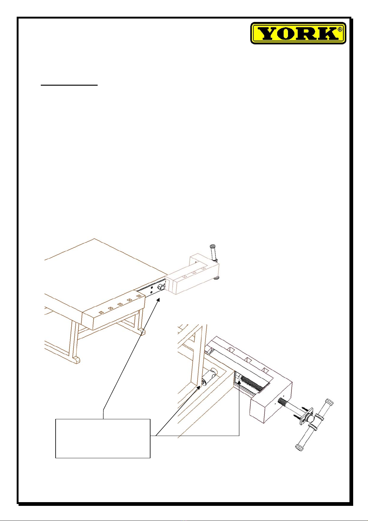
a) If the workbench has a collar, nut is secure sole piece and screw M8 from the inside the
workbench. If the workbench has no collar, spindle of the conduit cassette secure her position.
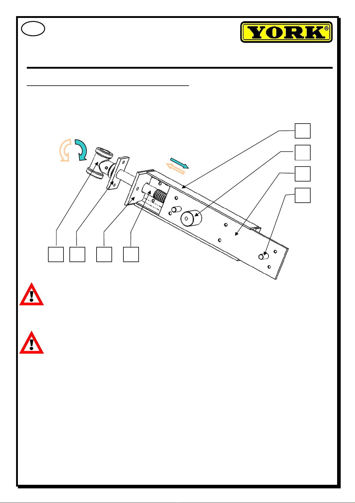
b) Prior to bolting spindle and nut, the face must unfastening and spindle draw out. See Fig .6b.
c) Vice installated insert clamping jaw to cover vice over hole for nut. Than follows put through
nut. See Fig.6a a 6b.
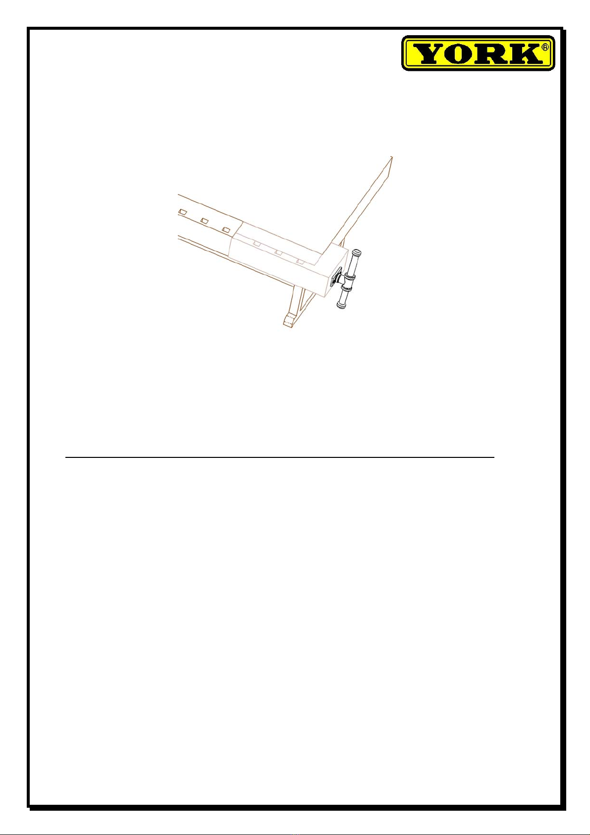
d) We bolt spindle and nut. We can fast the face screw-bolt again See Page 5, Fig.5.
Page 6 (of 7)
Fig.6a
Mounting nut on a
workbench
– put through after insert
j
aw over hole for nut Fig.6b

e) After tighten vice first is must to seat all edges of clamping jaw with the workbench board.
See Fig.7.
f) Finally, check the operation of the vice’s system. By turning the spindle (3) clockwise (CW)
the vice clamp. By turning the spindle (3) counter clockwise (CCW) the vice disengage.
Vice disassembly is done by reversing the steps described in this User Manual.
Page 7 (of 7)
Fig.7
This manual suits for next models
2
Table of contents