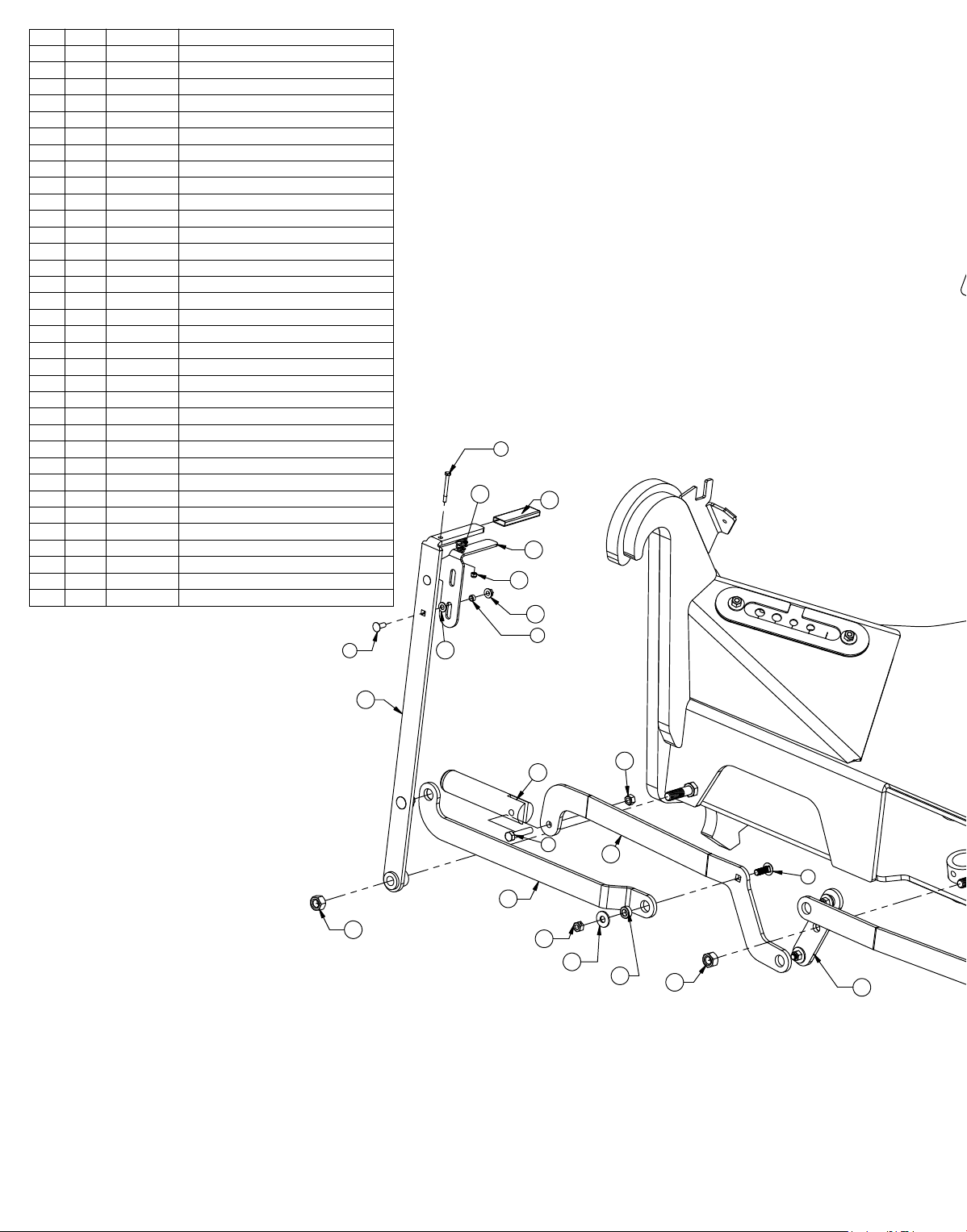
Grouser Products Ag Pro SS User manual

Date 1-1-2018PN: 63-19460
AG PRO SS
Owner’s Manual
&
Parts Book
Purchase Date
Serial Number
Model Number
Tractor Model
Dealer
SN: 10205064-...

2
Description Page
2-3
4
5
6
Initial Startup Instructions 7
8
9
10-14
15
16-17
18-19
20-23
24
To The Owner
Maintenance
Due to the harsh environment your equipment operates in, the following tasks should be
performed every 10 hours or less.

3
Safety Precautions
The Dozer:
Servicing the Dozer:
Storing the Dozer:
Torque - Dry (ft–lbs)
5/16 17 19 24 27
3/8 30 35 45 50
7/16 50 55 70 80
1/2 75 85 110 120
9/16 110 120 150 170
5/8 150 170 210 240
3/4 260 300 380 420
7/8 430 470 600 670
1 640 720 910 1020
Torque - Dry (ft-lbs)
Size
284
401
547
694

4

5
Lift System
23
18 28
24
25
22 20
10
14
23
16
Cylinder Part No. Description
26-34745 49-12278 Seal Kit 4.5” Bore x 2” Rod (658366) Nitrided Rod
* Parts Not Shown
Item #A for Claas Tractors (24-19444)
Item #B for Steiger (24-18907), New Holland (24-18907), and JD 9R Tractors (24-19423, 24-18883 or 24-19447)
Item #C for JD 9RX (24-19446), Versatile (24-19443) and Challenger Tractors (24-19433)
Detail A:
Scale 1:10
NO. QTY. PART NO. DESCRIPTION
1 1 11-18100-L Top Arm, Ag Pro S
2 1 11-18100-R Top Arm, Ag Pro S
3 2 16-20002 1/4" x 3/4 " Hex Bolt Gr 5 NC
4 4 16-20216 3/4" x 1-1/2" Hex Bolt Gr 5 NC
5 4 16-20217 3/4" x 1-3/4" Hex Bolt Gr 5 NC
6 4 16-20220 3/4" x 2-1/2" Hex Bolt Gr 5 NC
7 8 19-13515 Spacer, NR Pin
8 2 25-34342 Tappet Quick Coupler Male - Poppet Style
9 2 25-3457 Pioneer Dust Cap Lift (Orange)
10 2 26-34745 4.5 x 18 Hydraulic Cylinder
11 2 27-9503 Pinch Decal (Foot)
12 2 27-9504 Decal, Grouser Horizontal
13 12 27-9507 Decal, Grease
14 2 31-11699-10-8 JIC Union
15 2 31-34030 Bulkhead Run Tee JIC
16 2 31-34040 Straight JIC x O-Ring
17A* 2 31-6802-8-10 Straight Thread Elbow 45° JIC x O-Ring
17B,C 2 31-34051 Straight Thread Elbow 90° JIC x O-Ring
18 2 31-6400-10-8 Straight JIC x O-Ring
19 1 32-18630 Lift Frame, Ag Pro Plus
20 2 34-12932 Cylinder Saddle
21 1 34-14961 Manual Canister Small
22 2 34-16578 Hose Clamp (worm drive - 4.5)
NO. QTY. PART NO. DESCRIPTION
23 15 34-18888-OR -12 Orange - Spiral Band
24 1 35-12633-0515 51.5” x 1/2" -8JIC/-8JIC Hose
25 1 35-12633-0535 53.5” x 1/2" -8JIC/-8JIC Hose
26 1 35-12633-0665 66.5” x 1/2" -8JIC/-8JIC Hose
27 1 35-12633-0670 67” x 1/2" -8JIC/-8JIC Hose
28 2 35-18240 Lift Cylinder Steel Line
29A,B 2 35-30183 293” (24.42”) x 1/2" -8JIC/-8JIC Hose
29C 2 35-18953-320 320” (26.67”) x 1/2" -8JIC/-8JIC Hose
30 2 43-14725 Lift Frame / UC Pin
31 4 43-18120 Top Pin Weld
32 2 43-18127 Top Arm Pin Weld
33 2 43-18175 Lift Cyl Pin Weld
34 2 43-18635 Ag Pro Plus QA Pin
35 1 45-18110-L Male Quick Attach, Ag Pro S - Left
36 1 45-18110-R Male Quick Attach, Ag Pro S - Right
37 2 57-1530 3" OD X .75 ID X .25" HD Flat Washer
38 6 57-1811 2” Washer
39 2 57-20740 1/4" Flat Washer
40 10 57-20747 3/4" Flat Washer
41 12 58-9369 Straight 1/8" NPT Grease Zerk
42 2 70-20607 3/4" Hex Center Lock Nut NC
43 2 70-20807 3/4" Hex Jam Nut NF
4
37 38
32
41
12
36
35
1
2
19
33
41
740
5
34
30
40
4
41
740
41
6
9
8
21
39
3
42
24
25
17
31
29
26
15
13
43
10
11
27
A

6
15
9
14
Loop For Clarity.
10
10
3
13
All Hoses Should Be
Routed Through Hose
Loop. Hoses Are Shown
Outside Of The Hose
4
Top View - Some
Parts Not Shown For
Clarity
* Parts Now Shown
Item #A & B for Claas Tractors - 23-19461
Item #C for Steiger, New Holland, and JD Tractors - 23-18886
Item #D for Versatile and Challenger Tractors - 23-19459
No. Qty. Part No. Description
1 2 16-21125 1/2" x 1-1/4" Carriage Bolt Gr 5 NC
2 4 16-35C612 3/8" x 3/4" Flanged Bolt
3 4 25-34321 Tappet Quick Coupler Female
4 4 25-34342 Tappet Quick Coupler Male - Poppet Style
5* 2 25-3453 Pioneer Dust Cap Tilt (Green)
6* 2 25-3454 Pioneer Dust Plug Tilt (Green)
7* 2 25-3455 Pioneer Dust Cap Angle (Red)
8* 2 25-3456 Pioneer Dust Plug Angle (Red)
9 4 31-15199-8-8 JIC Union Elbow 90°
10A 4 31-34051 Straight Thread Elbow 90° JIC x O-Ring
10B 4 31-6802-08-10 Straight Thread Elbow 45° JIC x O-Ring
10C,D 8 31-34051 Straight Thread Elbow 90° JIC x O-Ring
11* 4 34-18888-GR -12 Green - Spiral Band
12* 4 34-18888-RD -12 Red - Spiral Band
13A,C 4 35-30183 293” (24.42”) x 1/2" -8JIC/-8JIC Hose w/165” Cordura
13D 4 35-30172 318” (24.42”) x 1/2" -8JIC/-8JIC Hose
14 2 35-31135 78" x 1/2" -8JIC/-8JIC Hose w/ Cordura
15 2 35-31136 81" x 1/2" -8JIC/-8JIC Hose w/ Cordura
16 2 44-14734 Female Coupler Retainer
17 1 44-16236 Female Coupler Mount
18 2 70-20604 1/2" Hex Center Lock Nut Gr 2 NC
19 4 70-20622 3/8" Flange Hex Nut Gr 5 NC
1,18 2,19
(Right Side Out)
Angle Right - Red Ring
(Left Side Out) Tilt Right - Green Ring
16
(Right Side Down)
(Left Side Down)
Angle Left - Red Ring
Tilt Left - Green Ring
17
Tractor Side - Hydraulic Hose Routing
Note: Refer to Diagram below for further information on hose routing and hose positions. The quantity and
location of the female couplers is determined by blade functionality.

7
Initial Startup Instructions
Lift Function:
Tilt Function:
Note: Damage will incur if blade stands are down during blade operation.
Angle Function:
NOTE: If blade does not function to the operator’s liking or preferred direction, swap the couplers at the rear
of the tractor or control the function location in the cab.

8
To Connect:
Note: Damage will incur if blade stands are down during blade operation.
To Disconnect:
Note: Blade should be o the ground when unlocking the blade.

9
Figure 3
Handle
Removable Handle
Hitch Clip Pin
Skid Shoe
Figure 1
Lever
Handle
Figure 2
Tilt Plates
Washers
Skid Shoe Adjustment:
the hitch clip pin and insert into the handle on the
Tilt Plate Adjustment:
If the clearance between the tilt frame and the tilt
plates is not meeting the recommended specication
of 1/16” - 1/8”, follow the steps below to adjust the tilt
plates.

10
23
5
2
14
15
28
29
9
24
7
33
27
19
4
16
26
26
34
25
8
31
27
32
4
26
19
21
13
12
20
17
10
11
186
1
30
22
NO. QTY. PART NO. DESCRIPTION
1 2 11-18495R1 Blade Stand
2 1 16-20011 1/4" x 2-3/4" Hex Bolt Gr 5 NC
3 1 16-20040 5/16" x 2-1/2" Hex Bolt Gr 5 NC
4 2 16-20130 1/2" x 2-1/2" Hex Bolt Gr 5 NC
5 1 16-20560 1" x 2-1/2" Gr.8 NC Hex Bolt
6 2 16-20561 1" x 2-3/4" Hex Bolt Gr.8 NC
7 2 16-21064 3/8" x 1" Carriage Bolt Gr 5 NC
8 4 16-21126 1/2" x 1-1/2" Carriage Bolt Gr 5 NC
9 2 19-13577 Bushing, Spacer
10 2 19-7774 1" x 1" Spring Bushing
11 2 27-2409 Pinch Decal (Hand)
12 1 32-17960R5 Tilt Frame Weld
13 1 32-19130R3 Angle Frame
14 1 34-17799 Latch Spring
15 1 39-14663R1 Latch
16 1 39-14665R3 Handle Weld
17 1 39-3072 Rubber Handle
18 2 43-15712 Pin, 3/4" x 3-1/4"
19 2 43-18486R1 AG Pro S QA Lock Pin
20 1 43-18491R1 Angle Pin Weld
21 2 43-7767 Cylinder Pin Clip
22 4 44-8490 Spacer
23 1 57-16928R1 Plate, Washer
24 2 57-20742 3/8 Flat Washer
25 4 57-20744 1/2" Flat Washer
26 6 70-20604 1/2" Center Lock Hex Nut
27 2 70-20607 3/4" Hex Center Lock Nut NC
28 1 70-20610 1/4" Nyloc Hex Nut Gr 5 NC
29 2 70-20622 3/8" Flange Hex Nut Gr 5 NC
30 2 70-20999 1" Hex Top Lock Nut Gr 8 NC (Yellow Zinc)
31 1 75-18480 Bell Crank Weld
32 1 75-18485R3 Link, Right Pin
33 1 75-18526 Link, Handle To Left Pin
34 1 75-18527 Link, Left Pin

11
Hydraulic Angle - Hydraulic Tilt (23-19421 - Page 1)
23
5
2
14
15
28
29
9
24
7
33
27
19
4
16
26
26
34
25
8
31
27
32
4
26
19
21
13
12
20
17
10
11
186
1
30
22
NO. QTY. PART NO. DESCRIPTION
1 2 11-18495R1 Blade Stand
2 1 16-20011 1/4" x 2-3/4" Hex Bolt Gr 5 NC
3 1 16-20040 5/16" x 2-1/2" Hex Bolt Gr 5 NC
4 2 16-20130 1/2" x 2-1/2" Hex Bolt Gr 5 NC
5 1 16-20560 1" x 2-1/2" Gr.8 NC Hex Bolt
6 2 16-20561 1" x 2-3/4" Hex Bolt Gr.8 NC
7 2 16-21064 3/8" x 1" Carriage Bolt Gr 5 NC
8 4 16-21126 1/2" x 1-1/2" Carriage Bolt Gr 5 NC
9 2 19-13577 Bushing, Spacer
10 2 19-7774 1" x 1" Spring Bushing
11 2 27-2409 Pinch Decal (Hand)
12 1 32-17960R5 Tilt Frame Weld
13 1 32-19130R3 Angle Frame
14 1 34-17799 Latch Spring
15 1 39-14663R1 Latch
16 1 39-14665R3 Handle Weld
17 1 39-3072 Rubber Handle
18 2 43-15712 Pin, 3/4" x 3-1/4"
19 2 43-18486R1 AG Pro S QA Lock Pin
20 1 43-18491R1 Angle Pin Weld
21 2 43-7767 Cylinder Pin Clip
22 4 44-8490 Spacer
23 1 57-16928R1 Plate, Washer
24 2 57-20742 3/8 Flat Washer
25 4 57-20744 1/2" Flat Washer
26 6 70-20604 1/2" Center Lock Hex Nut
27 2 70-20607 3/4" Hex Center Lock Nut NC
28 1 70-20610 1/4" Nyloc Hex Nut Gr 5 NC
29 2 70-20622 3/8" Flange Hex Nut Gr 5 NC
30 2 70-20999 1" Hex Top Lock Nut Gr 8 NC (Yellow Zinc)
31 1 75-18480 Bell Crank Weld
32 1 75-18485R3 Link, Right Pin
33 1 75-18526 Link, Handle To Left Pin
34 1 75-18527 Link, Left Pin

12
NO. QTY. PART NO. DESCRIPTION
34 3 16-20037 5/16" x 1-3/4" Hex Bolt Gr. 5 NC
35 2 16-20040 5/16" x 2-1/2" Hex Bolt Gr 5 NC
36 2 16-20134 1/2" x 3-1/2" Hex Bolt Gr. 5 NC
37 2 16-20219 3/4" x 2-1/4" Gr.5 Hex Bolt NC
38 4 16-35C612 3/8" x 3/4" Flange Bolt
39 3 18-19311-03-P-087 Hose Clamp
40 1 18-19311-03-P-100 Hose Clamp
41 3 18-19312-03 Twin Cover Plate
42 1 18-19313-03 Twin Stacking Bolt
43 1 18-19314-02 Twin Safety Plate
44 1 18-19315-L Hose Guide Weld
45 2 19-13515 Spacer, NR Pin
46 4 19-13577 Bushing, Spacer
47 4 25-34342 Tappet Quick Coupler Male - Poppet Style
48 2 25-3453 Pioneer Dust Cap Tilt (Green)
49 2 25-3455 Pioneer Dust Cap Angle (Red)
50 2 26-34747 4 x 8 Hydraulic Cylinder
51 2 26-34750 5 x 20 Cylinder Bushed Tube Ends
52 6 31-11492-8-8 Male JIC x Female JIC Swivel Nut Elbow 45°
53 2 31-11699-10-8 JIC Union
54 2 31-15676-LL-8-10 Straight Thread Extra Long Elbow 90° JIC x O-Ring
55 2 31-34030 Bulkhead Run Tee JIC
56 2 31-34040 Straight JIC x O-Ring
57 2 31-34041 Straight JIC x O-Ring
58 2 31-34042 Straight JIC x O-Ring
59 4 31-34050 Straight Thread Elbow 90° JIC x O-Ring
60 2 31-34051 Straight Thread Elbow 90° JIC x O-Ring
61 2 31-34060 Branch Tee JIC x O-Ring
62 2 34-12932 Cylinder Saddle
63 2 34-12933 Hose Clamp (worm drive - 5.0)
64* 4 34-18888-GR -12 Green - Spiral Band
65* 4 34-18888-RD -12 Red - Spiral Band
66 1 34-19217 Rubber Seal
67 2 35-12931 Formed Steel Line
68 2 35-19355 71" x 1/2" -8JIC/-8JIC Hose
69 1 35-19356 117.50" x 3/8" -8JIC/-8JIC Hose
70 1 35-19359 123" x 3/8" -8JIC/-8JIC Hose
71 2 35-30018 33" x 3/8" -8JIC/-8JIC Hose
72 2 35-30081 37" x 3/8" -8JIC/-8JIC Hose
73 4 35-31113 28" x 1/2" -8 JIC/-8 JIC Hose w/ Cordura
74 4 43-13580 Pin Weld
75 2 43-18487 Angle Cyl Base Pin
76 2 43-18490 Angle Cyl Rod Pin Weld
77 1 44-19218 Seal Clamp Plate
78 1 44-19219 Cover Plate
79 1 56-7772 Valve
80 4 57-20744 1/2" Flat Washer
81 2 57-20747 3/4" Flat Washer
82 2 70-20581 5/16" Hex Nut
83 6 70-20604 1/2" Center Lock Hex Nut
84 2 70-20607 3/4" Hex Center Lock Nut NC
85 2 70-20807 3/4" Hex Jam Nut NF
* Parts Not Shown
Cylinder Part No. Description
26-34747 49-12271 Seal Kit 4x8 Nitrided Rod, Clevis Ends
26-34750 49-12275 Seal Kit 5 x 20 Nitrided Rod
37
81
45
76
84
36
75
83
50
51
54
47
48
60
49
44 42 43
40
39
41
34
38
46
74
56
59
82
35
79
61
52
58
57
55
67
85
52
59
72
73
71
72
71
70
68
66
80
68
83
77
62
63
53
69
78

13
Hydraulic Angle - Hydraulic Tilt (23-19421 - Page 2)
NO. QTY. PART NO. DESCRIPTION
34 3 16-20037 5/16" x 1-3/4" Hex Bolt Gr. 5 NC
35 2 16-20040 5/16" x 2-1/2" Hex Bolt Gr 5 NC
36 2 16-20134 1/2" x 3-1/2" Hex Bolt Gr. 5 NC
37 2 16-20219 3/4" x 2-1/4" Gr.5 Hex Bolt NC
38 4 16-35C612 3/8" x 3/4" Flange Bolt
39 3 18-19311-03-P-087 Hose Clamp
40 1 18-19311-03-P-100 Hose Clamp
41 3 18-19312-03 Twin Cover Plate
42 1 18-19313-03 Twin Stacking Bolt
43 1 18-19314-02 Twin Safety Plate
44 1 18-19315-L Hose Guide Weld
45 2 19-13515 Spacer, NR Pin
46 4 19-13577 Bushing, Spacer
47 4 25-34342 Tappet Quick Coupler Male - Poppet Style
48 2 25-3453 Pioneer Dust Cap Tilt (Green)
49 2 25-3455 Pioneer Dust Cap Angle (Red)
50 2 26-34747 4 x 8 Hydraulic Cylinder
51 2 26-34750 5 x 20 Cylinder Bushed Tube Ends
52 6 31-11492-8-8 Male JIC x Female JIC Swivel Nut Elbow 45°
53 2 31-11699-10-8 JIC Union
54 2 31-15676-LL-8-10 Straight Thread Extra Long Elbow 90° JIC x O-Ring
55 2 31-34030 Bulkhead Run Tee JIC
56 2 31-34040 Straight JIC x O-Ring
57 2 31-34041 Straight JIC x O-Ring
58 2 31-34042 Straight JIC x O-Ring
59 4 31-34050 Straight Thread Elbow 90° JIC x O-Ring
60 2 31-34051 Straight Thread Elbow 90° JIC x O-Ring
61 2 31-34060 Branch Tee JIC x O-Ring
62 2 34-12932 Cylinder Saddle
63 2 34-12933 Hose Clamp (worm drive - 5.0)
64* 4 34-18888-GR -12 Green - Spiral Band
65* 4 34-18888-RD -12 Red - Spiral Band
66 1 34-19217 Rubber Seal
67 2 35-12931 Formed Steel Line
68 2 35-19355 71" x 1/2" -8JIC/-8JIC Hose
69 1 35-19356 117.50" x 3/8" -8JIC/-8JIC Hose
70 1 35-19359 123" x 3/8" -8JIC/-8JIC Hose
71 2 35-30018 33" x 3/8" -8JIC/-8JIC Hose
72 2 35-30081 37" x 3/8" -8JIC/-8JIC Hose
73 4 35-31113 28" x 1/2" -8 JIC/-8 JIC Hose w/ Cordura
74 4 43-13580 Pin Weld
75 2 43-18487 Angle Cyl Base Pin
76 2 43-18490 Angle Cyl Rod Pin Weld
77 1 44-19218 Seal Clamp Plate
78 1 44-19219 Cover Plate
79 1 56-7772 Valve
80 4 57-20744 1/2" Flat Washer
81 2 57-20747 3/4" Flat Washer
82 2 70-20581 5/16" Hex Nut
83 6 70-20604 1/2" Center Lock Hex Nut
84 2 70-20607 3/4" Hex Center Lock Nut NC
85 2 70-20807 3/4" Hex Jam Nut NF
* Parts Not Shown
Cylinder Part No. Description
26-34747 49-12271 Seal Kit 4x8 Nitrided Rod, Clevis Ends
26-34750 49-12275 Seal Kit 5 x 20 Nitrided Rod
37
81
45
76
84
36
75
83
50
51
54
47
48
60
49
44 42 43
40
39
41
34
38
46
74
56
59
82
35
79
61
52
58
57
55
67
85
52
59
72
73
71
72
71
70
68
66
80
68
83
77
62
63
53
69
78

14
Hydraulic Angle - Hydraulic Tilt (23-19421 - Page 3)
NO. QTY. PART NO. DESCRIPTION
86 2 31-13933-2-2 1/8” NPT Street Elbow
87 2 58-18994-0430 Grease Hose w/ Long Bulkhead (w/lock nut and grease zerk)
88 2 58-18994-0570 Grease Hose w/ Long Bulkhead (w/lock nut and grease zerk)
NO. QTY. PART NO. DESCRIPTION
86 2 31-13933-2-2 1/8” NPT Street Elbow
87 2 58-18994-0430 Grease Hose w/ Long Bulkhead (w/lock nut and grease zerk)
88 2 58-18994-0570 Grease Hose w/ Long Bulkhead (w/lock nut and grease zerk)
87
86
88
Left Angle Base
View From Front Of Angle Frame
Top Pivot Pin
Bottom Pivot Pin
Right Angle Base

15
Hydraulic Schematic
Left Tilt
AngleCylinderLeft
AngleCylinderRight
Tilt Quick Connects
Left Tilt Cylinder
Left Lift Cylilnder
Female Quick Connects At Rear Of Tractor
Valve
B
A
D
C
Extend &
& Ring
Red Cap
& Ring
Red Cap
1 Orange Ring
Orange Cap &
& Ring
Green Cap
& Ring
Green Cap
& Ring
Green Cap
& Ring
Green Plug
Right Tilt
Retract Extend
Right Angle
Retract &
Left Angle
Retract
Lift DownLift Up
Angle Quick Connects
Right Tilt Cylinder
Right Lift Cylilnder
Right Angle
& Ring
Green Cap
& Ring
Green Plug
& Ring
Red Plug
& Ring
Red Plug
& Ring
Red Cap
& Ring
Red Cap
Rings
2 Orange
Rings
2 Orange
Rings
1 Orange
Ring
1 Orange
2 Orange Rings
Orange Cap &
Extend &
Left AngleLeft Tilt
Retract &
Right Tilt
Extend

16
Blade Assembly (15-19250-XX-A)
NO. PART NO. DESCRIPTION 12' 14' 16' 18' 20'
1 15-19250-12 R1 Ag Pro SS Blade - 12' 1 - - - -
1 15-19250-14 R1 Ag Pro SS Blade - 14' - 1 - - -
1 15-19250-16 R1 Ag Pro SS Blade - 16' - - 1 - -
1 15-19250-18 R1 Ag Pro SS Blade - 18' - - - 1 -
1 15-19250-20 R1 Ag Pro SS Blade - 20'
----1
2 16-18945 1" x 3" Hex Bolt Gr 5 NC - Short Thread
22222
3 16-20558 1" x 2" Hex Bolt Gr. 8 NC
33333
4 16-20562 1" x 3" Hex Bolt Gr.8 NC 12 12 12 12 12
5 16-21666 5/8" x 1-3/4" Plow Bolt Gr 5 NC
44444
6 16-21748 3/4" X 2" Plow Bolt Gr 8 NC 24 28 32 36 40
7 18-18498-L R2 Ratchet Keeper - Left
11111
8* 18-18498-R R2 Ratchet Keeper - Right
11111
9 19-7774 1" x 1" Spring Bushing
22222
10* 27-14842-12 12' Decal 1 - - - -
11 27-14842-14 14' Decal - 1 - - -
12* 27-14842-16 16' Decal - - 1 - -
13* 27-14842-18 18' Decal - - - 1 -
14* 27-14842-20 20' Decal
----1
15 27-14845 Ag Pro Decal
11111
16 27-40956 Silage Special Decal
11111
17 27-40917 Ratchet Holder Storage Decal
11111
18* 29-11118-6 6' - 3/4”x 8” Cutting Edge 2 - - 3 2
19 29-11118-7 7' - 3/4”x 8” Cutting Edge - 2 - - -
20* 29-11118-8 8' - 3/4”x 8” Cutting Edge - - 2 - 1
21 34-17567 Handle, Ratchet Jack
22222
22 34-17565 Skid Shoe Ratchet Jack
11111
23 43-18463 1” x 2.75” Pin
22222
24 43-18943 3/16” x 1-1/2” Cotter Pin
22222
25 43-7767 Cylinder Pin Clip
22222
26 44-3749R1 Backdrag Brace Plate
11111
27 50-15458 12” Round Mushroom Skid Shoe
22222
28 50-17545 R3 Mushroom Shoe Assembly
22222
29 52-8204 Tilt Plate
44444
30 57-20749 1" Flat Washer 12 12 12 12 12
31 70-20646 5/8" Hex Top Lock Nut Gr 5 NC
44444
32 70-20647 3/4" Hex Top Lock Nut Gr 5 NC 1 29 32 36 40
33 70-20999 1" Hex Top Lock Nut Gr 8 NC (YZ) 22222
* Parts Not Shown
NO. PART NO. DESCRIPTION 12' 14' 16' 18' 20'
1 15-19250-12 R1 Ag Pro SS Blade - 12' 1 - - - -
1 15-19250-14 R1 Ag Pro SS Blade - 14' - 1 - - -
1 15-19250-16 R1 Ag Pro SS Blade - 16' - - 1 - -
1 15-19250-18 R1 Ag Pro SS Blade - 18' - - - 1 -
1 15-19250-20 R1 Ag Pro SS Blade - 20'
----1
2 16-18945 1" x 3" Hex Bolt Gr 5 NC - Short Thread
22222
3 16-20558 1" x 2" Hex Bolt Gr. 8 NC
33333
4 16-20562 1" x 3" Hex Bolt Gr.8 NC 12 12 12 12 12
5 16-21666 5/8" x 1-3/4" Plow Bolt Gr 5 NC
44444
6 16-21748 3/4" X 2" Plow Bolt Gr 8 NC 24 28 32 36 40
7 18-18498-L R2 Ratchet Keeper - Left
11111
8* 18-18498-R R2 Ratchet Keeper - Right
11111
9 19-7774 1" x 1" Spring Bushing
22222
10* 27-14842-12 12' Decal 1 - - - -
11 27-14842-14 14' Decal - 1 - - -
12* 27-14842-16 16' Decal - - 1 - -
13* 27-14842-18 18' Decal - - - 1 -
14* 27-14842-20 20' Decal
----1
15 27-14845 Ag Pro Decal
11111
16 27-40956 Silage Special Decal
11111
17 27-40917 Ratchet Holder Storage Decal
11111
18* 29-11118-6 6' - 3/4”x 8” Cutting Edge 2 - - 3 2
19 29-11118-7 7' - 3/4”x 8” Cutting Edge - 2 - - -
20* 29-11118-8 8' - 3/4”x 8” Cutting Edge - - 2 - 1
21 34-17567 Handle, Ratchet Jack
22222
22 34-17565 Skid Shoe Ratchet Jack
11111
23 43-18463 1” x 2.75” Pin
22222
24 43-18943 3/16” x 1-1/2” Cotter Pin
22222
25 43-7767 Cylinder Pin Clip
22222
26 44-3749R1 Backdrag Brace Plate
11111
27 50-15458 12” Round Mushroom Skid Shoe
22222
28 50-17545 R3 Mushroom Shoe Assembly
22222
29 52-8204 Tilt Plate
44444
30 57-20749 1" Flat Washer 12 12 12 12 12
31 70-20646 5/8" Hex Top Lock Nut Gr 5 NC
44444
32 70-20647 3/4" Hex Top Lock Nut Gr 5 NC 1 29 32 36 40
33 70-20999 1" Hex Top Lock Nut Gr 8 NC (YZ) 22222
15
3
26
9
4
30
29
6
19
32
28
27
5
23
24
22
25
7
33
221
116
31
17
11

17
Name Plate (18-19415-A & 18-14830-A)
NO. QTY. PART NO. DESCRIPTION
1 8 16-21064 3/8" x 1" Carriage Bolt Gr 5 NC
2 1 44-19415 Ag Pro Silage Special Name Plate
3* 1 44-14830 Custom Name Plate
4 8 70-20622 3/8" Flange Hex Nut Gr 5 NC
NO. QTY. PART NO. DESCRIPTION
1 8 16-21064 3/8" x 1" Carriage Bolt Gr 5 NC
2 1 44-19415 Ag Pro Silage Special Name Plate
3* 1 44-14830 Custom Name Plate
4 8 70-20622 3/8" Flange Hex Nut Gr 5 NC
4
* Parts Not Shown
1
2

18
NANT Blade Assembly (15-40915-XX-A)
DWG. NO.: 40915-XX-A
ITEM NO. 40915-12-A/QTY. 40915-14-A/QTY. 40915-16-A/QTY. 40915-18-A/QTY. 40915-20-A/QTY. PART NO. DESCRIPTION
1 4 4 4 4 4 16-20125 1/2" x 1-1/2" Hex Bolt Gr. 5 NC
2 8 8 8 8 8 57-20744 1/2" Washer
3 1 1 1 1 1 44-19580R2 Cover Plate
4 4 4 4 4 4 70-20604 1/2" Hex Center Lock Nut Gr 2 NC
5 1 1 1 1 1 75-18480 Bell Crank Weld
6 2 2 2 2 2 43-18486 AG Pro SS QA Lock Pin
7 2 2 2 2 2 75-19576 Link, Bell Crank To Pin
8 1 1 1 1 1 75-19575 Plate, Link
9 1 1 1 1 1 39-14665 Handle Weld
10 4 4 4 4 4 44-8490 Spacer
9
5
1
2
3
2
4
6
78
10

19
NANT Blade Assembly (15-40915-XX-A)
DWG. NO.: 40915-XX-A
ITEM NO. 40915-12-A/QTY. 40915-14-A/QTY. 40915-16-A/QTY. 40915-18-A/QTY. 40915-20-A/QTY. PART NO. DESCRIPTION
1 4 4 4 4 4 16-20125 1/2" x 1-1/2" Hex Bolt Gr. 5 NC
2 8 8 8 8 8 57-20744 1/2" Washer
3 1 1 1 1 1 44-19580R2 Cover Plate
4 4 4 4 4 4 70-20604 1/2" Hex Center Lock Nut Gr 2 NC
5 1 1 1 1 1 75-18480 Bell Crank Weld
6 2 2 2 2 2 43-18486 AG Pro SS QA Lock Pin
7 2 2 2 2 2 75-19576 Link, Bell Crank To Pin
8 1 1 1 1 1 75-19575 Plate, Link
9 1 1 1 1 1 39-14665 Handle Weld
10 4 4 4 4 4 44-8490 Spacer
9
5
1
2
3
2
4
6
78
10

20
ITEM
NO. PART NO. HAHT 2-Stick HANT 2-Stick or
HAHT Electric
NAHT or
HANT Electric
12-20 or 3-5
Blades DESCRIPTION
1 16-18957 4 - - - 5/16” x 3-1/4” Allen Head Screw
2 16-35C612 3 3 3 3 3/8" x 3/4" Flange Bolt
3 16-812525 - 2 2 2 8mm x 1.25mm x 25mm Metric Hex Bolt Gr 10.9
4 18-18430R1 1 1 1 - Quick Coupler Mount
5 18-18514 - - - 1 Quick Coupler Mount
6 25-18956 - 1 - 1 Multi-Coupling Plate - 4 Port Parking Station
7 25-18961 1 - - - Multi-Coupling Plate - 5/6 Port Parking Station
8 25-19657 - - 1 - Multi-Coupling Plate - 2 Port Parking Station
9 25-19861 1 - - - Multi-Coupling Plate - 5 Port - Fixed
10 25-19862 1 - - - Multi-Coupling Plate - 5 Port - Mobile
11 25-19863 1 - - - Multi-Coupling Plate - 5 Port - Cap
12 25-19864 - 1 - 1 Multi-Coupling Plate - 4 Port Fixed
13 25-19866 - 1 - 1 Multi-Coupling Plate - 4 Port Mobile
14 25-19867 - 1 - 1 Multi-Coupling Plate - 4 Port - Cap
15 25-19868 - - 1 - Multi-Coupling Plate - 2 Port - Fixed
16 25-19869 - - 1 - Multi-Coupling Plate - 2 Port - Mobile
17 25-19871 - - 1 - Multi-Coupling Plate - 2 Port - Cap
18 31-34040 5 4 2 4 Straight JIC x O-Ring
19 31-34150 5 4 2 4 Straight Thread Elbow 45° JIC x O-Ring (6802-8-8)
20 70-20611 4 - - - 5/16" Nyloc Hex Nut Gr 5 NC
4 Port Multi Coupler -12-20 or 3-5 Sliders
5 Port Multi Coupler -HAHT 2-Stick
18
11
220
4
9
10
1
19
7
1. Parking Stations are located on the angle frames or blades. Place the Cap in the Parking Stations when
blade is in use. When disconnecting the blade, place the Cover on the Fixed Multi-Coupler and the Mobile
Multi-Coupler in the Parking Station.
2. Apply a heavy duty silicone spray lubricant to pins to protect from corrosion.
14
3
12
13
6
13
5
12
Tilt Base
Angle Rod (2-Stick)
Right Angle BaseLeft Angle Base
Tilt Rod
2 Port Multi Coupler - NAHT or HANT Electric
15
16
8
17
4 Port Multi Coupler -HANT 2-Stick or HAHT Electric
Table of contents
Other Grouser Products Tractor manuals