SEFRAM SET100DP User manual

SEQUENCER WITH
DIFFERENTIAL PRESSURE
SWITCH
Technical brochure
FI 72.0483.0720E
Page 1 sur 43 - 1 -Page 1 sur 43 - 1 - - 1 - - 1 - - 1 -
Outputs SV AC version
Not ATEX version ATEX version
ABS Box PC Box
PLACE GUTENBERG - 59175 TEMPLEMARS (France)
Tel: +33(0)3 20 60 49 49 - Fax: +33(0)3 20 95 59 62
Email: contact@sefram.eu Web: www.sefram.eu

SEQUENCER WITH
DIFFERENTIAL PRESSURE
SWITCH
Technical brochure
FI 72.0483.0720E
Page 2 sur 43 - 2 -Page 2 sur 43 - 2 - - 2 - - 2 - - 2 -
SOMMAIRE :
DESCRIPTION :
The SET100DP is an adjustable device for control and full
automatization of declogging equipment, whose declogging is
done by pressured air injections.
It can perform various functions: declogging sequence, filter load
loss measurement, compressed air pressure measurement, dust
rejection monitoring associated with our CDM dust probe,
communication with the outside.
Permanent control of differential pressure and compressed air
allows an optimal efficiency according to the whole parameters, for
any type of exploitation and product.
It is equipped with:
- 18 outputs for solenoid valves (SV).
- electric default control.
- 4 AON inputs (run order, compressed air control,
accelerated running, forced running)
- 4 relay outputs for fault or alarm reports, running report, run
order report.
Depending equipment :
- The number of solenoid outputs can be extended. Possibility
of obtaining up to 162 SV outputs with 8 additional SV
extension boxes.
- Differential pressure sensor for load loss dP measurement
- Analog output 4-20mA for the report of the load loss dP
measurement information.
- Pressure sensor for measuring compressed air A/C.
- Analog output 4-20mA for the report of the compressed air
A/C measurement.
- Communication with CDM dust rejection control
- External communication via MODBUS RTU fieldbus.
Possibility of external gateway to other bus for example
PROFIBUS DP.
The device is adjustable, according to the use of it, with several
levels, protected by passwords.
All the running parameters can be seen and adjusted on the
front panel of the device, thanks to a graphic colour touch screen
Interface is multilingual.
Evolution of the declogging cycle, the running defaults and the
pressure load loss measure are clearly displayed and detailed.
The load loss dP and compressed air measurements, dust
rejection are also displayed and a graphical representation
allowing to follow their evolutions.
Note: this manual is based on a completely equipped device: the
functions and terminal blocks of options not present are not to be
taken into account.
Page
- DESCRIPTION
2
- CHARACTERISTICS
3
- DIMENSIONS AND MOUNTING
5
- PROTECTION
11
- CONNECTIONS
14
- USER INTERFACE
Main page
Load loss dP page
Compressed air A/C page
Rejection CDM
Sequencer informations page
Main menu page
Language page
Security levels page
Parameters menu page
Sequencer parameters page
Load loss dP parameters page
Output 4-20mA dP parameters page
Compressed air A/C parameter page
Output 4-20mA A/C parameter page
Fan parameters page
Rejection control CDM parameters
SV extension parameters page
Customer COM parameters page
Manual running page
System info page
19
19
21
22
23
24
25
25
26
27
28
29
30
31
33
34
35
36
37
38
39
- RUNNING
39
- FAULTS
40
- AON INPUTS
41
- RELAY OUTPUTS
41
- WARNING
42
- CALIBRATION
42
- WARRANTY
42
- CERTIFICATE
42
- GENERAL INSTRUCTIONS OF
SAFETY, ASSEMBLY,
COMMISSIONNING AND
MAINTENANCE
43

SEQUENCER WITH
DIFFERENTIAL PRESSURE
SWITCH
Technical brochure
FI 72.0483.0720E
Page 3 sur 43 - 3 -Page 3 sur 43 - 3 - - 3 - - 3 - - 3 -
CARACTERISTIQUES :
- Supply voltage (nominal voltage) :
Depending version:
115V/230V 10 % 50-60 Hz
24V/48V 10 % 50-60 Hz
- Consumption (nominal current) maxi :
5VA + SV consumption
- Protection :
By fuses 5x20mm (see table 1)
- Tension électrovannes:
According supply voltage (see table 1)
24V/48V/115V/230V 50-60Hz
Depending version Pmax 25VA or 45VA
(ATEX version: only 25VA)
(Pmax : 45VA only available if version with SV connection by
multiconductor cable ; the choice is made at the order)
- AON inputs characteristics:
voltage : 24VDC supplied by the device
Load current +/- 1mA
- Relay contact characteristics :
Dry contact. max: 125VAC/0.3A - 30VDC/1A
(to be protected by user)
- Ambient operating temperature :
not ATEX version : -20° à 60°C
ATEX version : -20°C à 55°C
- Storage temperature :
-20° to 70° C
- Box :
ABS material - IP65 (not ATEX version)
PC material - IP65 (ATEX or not ATEX version)
- Display :
Touch screen / size 4.3 inches / resolution 480x272
65536 colours / Buzzer
SEQUENCER :
- maxi outputs quantity
not ATEX version : 18
(possibility version with connection of two SV per output if SV
connection by multiconductor cable, the choice is made at order
; so 36 SV)
ATEX version : 18
Expendable to 162 (with adjunction of 8 extensions of 18)
- activation time of an output (T1)
from 3/100th to 255/100th of a second
- idle time between two outputs (T2 / T2A)
from 1 to 255 seconds
- rest time between two cycles (T3)
from 0 to 255 minutes
- forced declogging time (T4)
from 0 to 255 hours
- Number of cycles if fan stopped
from 0 to 255 cycles
- Number of cycle in manual operation
from 0 to 255 cycles

SEQUENCER WITH
DIFFERENTIAL PRESSURE
SWITCH
Technical brochure
FI 72.0483.0720E
Page 4 sur 43 - 4 -Page 4 sur 43 - 4 - - 4 - - 4 - - 4 -
LOAD LOSS DP MEASURE :
- Scale
0-500 daPa
Display accuracy : 1 daPa
- maxi pressure
1400 mbar
- accuracy
1.5% on sensor maxi scale (100 mbar)
→ from 0 to 50°C this accuracy takes into consideration linearity,
hysteresis, temperature and repetitivity effects
- humidity
0% to 95% RH –not condensed
- response time dP order
1 second
- response time alarm high/low/T2A threshold
5 seconds
- 4-20mA output
Integrated supply, not isolated - Maxi load : <500 Ohms
COMPRESSED AIR PRESSURE MEASURE
A/C
- Scale
0 - 6 Bar
Display accuracy : 0.1 Bar
- maxi pressure
17 Bar
- accuracy
1.5% on sensor maxi scale (10 Bar)
→ from 0 to 50°C this accuracy takes into consideration linearity,
hysteresis, temperature and repetitivity effects
- humidity
0% to 95% RH –not condensed
- response time operating threshold
1 second
- response time low alarm
5 seconds
- 4-20mA output
Integrated supply, not isolated - Maxi load : <500 Ohms
COMMUNICATION WITH EXTERIOR
(CUSTOMER COM):
- protocol
MODBUS –RTU
RS485 (2 wires) - not isolated
Note : External gateway available to other type of network.
- ID
from 1 to 147
- speed
2400, 4800, 9600, 19200, 38400, 57600 or 115200 bauds
- Type
8N1, 8N2, 8E1 or 8O1
COMMUNICATION WITH DUST REJECTION
CONTROLLER CDM:
- type
RS485 (2 wires) –not isolated
- supply
The 24VDC power supply required for the CDM is provided by
the device
+ fuse protection 5x20mm - 250mA fast
COMMUNICATION WITH SV EXTENSION
BOXES:
- type
RS485 (2 wires) –not isolated

SEQUENCER WITH
DIFFERENTIAL PRESSURE
SWITCH
Technical brochure
FI 72.0483.0720E
Page 5 sur 43 - 5 -Page 5 sur 43 - 5 - - 5 - - 5 - - 5 -
DIMENSIONS AND MOUNTING MOUNTING (not ATEX version) :
Main Box / front side, right side and left side :
1
dP + pressure connection
(dirty air side)
Connection for 6/8mm tube
2
dP - pressure connection
(clean air side)
Connection for 6/8mm tube
3
Compressed air pressure connection
Connection for 4/6mm tube (A/C)
4
ISO16 : 4-20mA output dP
5
ISO16 : 4-20mA output A/C
6
ISO16b : AON input I1
7
ISO20b : relay outputs
8
ISO16b : AON input I2
9
ISO16b : AON input I3
10
ISO16b : AON input I4
11
ISO20 : supply
12
ISO16b : extension com
13
ISO16b : CDM com
14
ISO16b : customer com
On the underside of the box:
SV connection area
see next page
Tightening capacity of glands :
ISO 16
from 4 to 8 mm
ISO 16b
from 5 to 10 mm
ISO 20
from 7.5 to 13 mm
ISO 20b
from 9.5 to 15 mm
ISO 25
from 13 to 19 mm

SEQUENCER WITH
DIFFERENTIAL PRESSURE
SWITCH
Technical brochure
FI 72.0483.0720E
Page 6 sur 43 - 6 -Page 6 sur 43 - 6 - - 6 - - 6 - - 6 -
Main Box ou SV Extension Box / undersize of the box:
Individual cables
version
(1 common
+ ground per SV)
18xISO16
Multiconductors cables
version
(3 common
+ 3 ground for 3x6 EV)
3xISO20b
Multiconductors cables
version
if version with possibility
of connection of two SV
per output
if version
pmax SV: 45VA
(6 common
+ 6 ground for
6x6 EV)
6xISO20b

SEQUENCER WITH
DIFFERENTIAL PRESSURE
SWITCH
Technical brochure
FI 72.0483.0720E
Page 7 sur 43 - 7 -Page 7 sur 43 - 7 - - 7 - - 7 - - 7 -
SV extension box :
1
ISO20 : supply
2
ISO16b : extension com input
3
ISO16b : extension com output
Main box or SV extension box / behind side of the box:
On the underside of the box:
SV connection area
see previous page

SEQUENCER WITH
DIFFERENTIAL PRESSURE
SWITCH
Technical brochure
FI 72.0483.0720E
Page 8 sur 43 - 8 -Page 8 sur 43 - 8 - - 8 - - 8 - - 8 -
DIMENSIONS AND MOUNTING (ATEX version) : Only version SV Pmax=25VA
Main Box /front side, right side and left side :
On the underside of the box:
SV connection area
see next page
1
2
3
4
5
6
7
8
9
10
11
12
13
14
1
supply
2
extension com
3
CDM com
4
customer com
5
dP - pressure connection
(clean air side)
Connection for 6/8mm tube
6
dP + pressure connection
(dirty air side)
Connection for 6/8mm tube
7
Compressed air pressure connection
Connection for 4/6mm tube (A/C)
8
4-20mA output dP
9
4-20mA output A/C
10
AON input I4
11
relay outputs
12
AON input I2
13
AON input I3
14
AON input I1

SEQUENCER WITH
DIFFERENTIAL PRESSURE
SWITCH
Technical brochure
FI 72.0483.0720E
Page 9 sur 43 - 9 -Page 9 sur 43 - 9 - - 9 - - 9 - - 9 -
Main Box or extension SV box / undersize of the box:
Individual cables
version
(1 common
+ ground per SV)
18xISO16
Multiconductors cables
version
(3 common
+ 3 ground for 3x6 EV)
3xISO20b
Clamping capacity of the cable glands:
Identify the cable glands used by the markings on the cable glands and refer to the tightening capacity of the cable
glands specified in the instructions of the cable gland manufacturer (document supplied with brochure + ATEX
instructions).

SEQUENCER WITH
DIFFERENTIAL PRESSURE
SWITCH
Technical brochure
FI 72.0483.0720E
Page 10 sur 43 - 10 -Page 10 sur 43 - 10 - - 10 - - 10 - - 10 -
SV extension box : front side, right side and left side (note : undersize of the box →same as main box)
1
supply
2
extension com input
3
extension com output
1
2
3

SEQUENCER WITH
DIFFERENTIAL PRESSURE
SWITCH
Technical brochure
FI 72.0483.0720E
Page 11 sur 43 - 11 -Page 11 sur 43 - 11 - - 11 - - 11 - - 11 -
PROTECTION :
Table 1: Supply Voltage / Solenoid Valves Voltage / Fuses
If version, Pmax SV : 25VA
Supply voltage
230VAC
115VAC
Solenoides valves voltage
230VAC
48VAC
24VAC
115VAC
48VAC
24VAC
fuse F1 caliber
F1A
F1A
fuse F2 caliber
F1A
F1A
fuse F3 caliber
F1A
F1A
Supply voltage
48VAC
24VAC
Solenoides valves voltage
48VAC
24VAC
24VAC
fuse F1 caliber
F1.6A
F1.6A
fuse F2 caliber
F1.6A
F1.6A
fuse F3 caliber
F1A
F1A
If version, Pmax SV : 45VA
Supply voltage
230VAC
115VAC
Solenoides valves voltage
230VAC
48VAC
24VAC
115VAC
48VAC
24VAC
fuse F1 caliber
F1A
F1A
fuse F2 caliber
F1A
F1A
fuse F3 caliber
F500mA
F1.6A
F2.5A
F500mA
F1.6A
F2.5A
Supply voltage
48VAC
24VAC
Solenoides valves voltage
48VAC
24VAC
24VAC
fuse F1 caliber
F2.5A
F2.5A
T2.5A
fuse F2 caliber
F2.5A
F2.5A
T2.5A
fuse F3 caliber
F1.6A
F2.5A
F2.5A
The protection fuses are accessible after dismounting the front panel of the box. The fuses are located at the top
left of the board:
Fuses F1 and F2 :
Device general protection
5x20mm
Caliber: see table 1
Fuse F3 :
SV outputs protection
5x20mm
Caliber: see table 1

SEQUENCER WITH
DIFFERENTIAL PRESSURE
SWITCH
Technical brochure
FI 72.0483.0720E
Page 12 sur 43 - 12 -Page 12 sur 43 - 12 - - 12 - - 12 - - 12 -
VOLTAGE CHOICE :
It is possible according to the version of the device to set differently the supply voltage and the solenoid valves
voltage of that made by default in factory answering the ordered version. Warning: the device must be switched off.
Notes:
- The supply choices "115V / 230V" or "24 / 48V" can be made only with order.
- If supply voltage "115V / 230V", the voltage choice of solenoid valves " 24V or 48V " can be made only with
order
See the table below for the possible settings according to the version of the box :
ACCORDING THE VERSION
SUPPLY VOLTAGE /
SOLENOIDE VALVES
VOLTAGE
POSITION OF THE JUMPERS :
230VAC / 230VAC
48VAC / 48VAC
115VAC / 115VAC
24VAC / 24VAC
Jumper on :
S1 / S2 / S4
Nothing on :
S3 / S5 / S6
Jumper on :
S1 / S2 / S3
Nothing on :
S4 / S5 / S6

SEQUENCER WITH
DIFFERENTIAL PRESSURE
SWITCH
Technical brochure
FI 72.0483.0720E
Page 13 sur 43 - 13 -Page 13 sur 43 - 13 - - 13 - - 13 - - 13 -
230VAC / 24VAC
230VAC / 48VAC
115VAC / 24VAC
115VAC / 48VAC
WARNING : a modification of the supply voltage and/or the solenoid valves voltage requires to
update the descriptive label placed outside of the box.
Jumper on :
S4 / S5 / S6
Nothing on :
S1 / S2 / S3
Jumper on :
S3 / S5 / S6
Nothing on :
S1 / S2 / S4
SEQUENCER WITH
DIFFERENTIAL PRESSURE
SWITCH
Technical brochure
FI 72.0483.0720E
Page 14 sur 43 - 14 -Page 14 sur 43 - 14 - - 14 - - 14 - - 14 -
CONNECTIONS:
Connections must be done when power off
Connections terminals are reachable after dismounting the front panel of the box.
According to configuration of the device, some terminals may not be included.
Cable strings will be flexible and will have a section between 0.5 and 1.5 mm2.
Power supply of the device:
The power supply for the device is connected in the upper part to the left of the board :
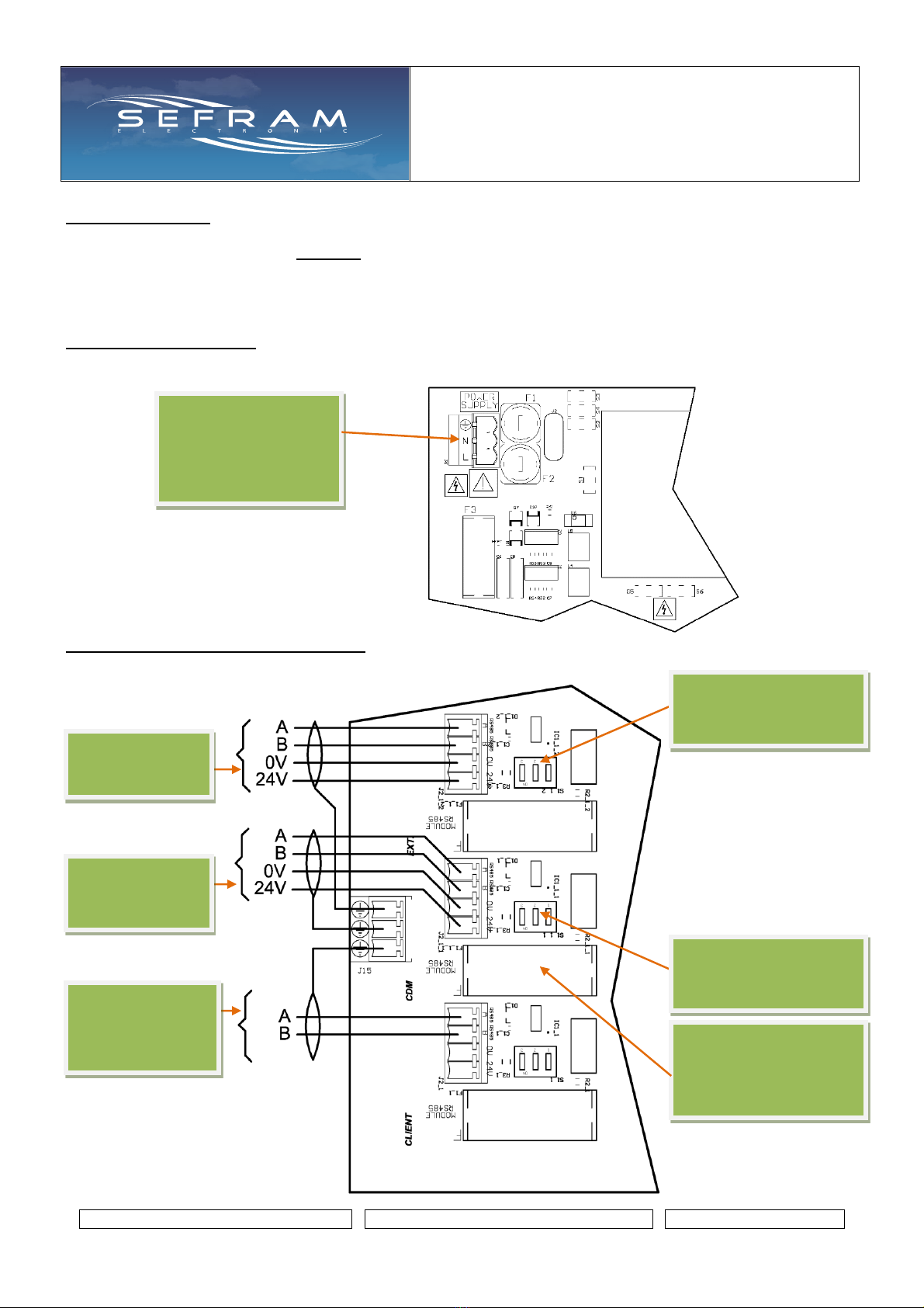
Communication extension, CDM, customer:
These connections are located in the lower part, to the left of the board:
Supply
According version
115V/230V
24V/48V
50/60Hz
Toward SV
extension boxes
Toward dust
rejection
controler CDM
Customer
communication
RS485
Modbus RTU
3 micro-switches to turn
ON
(extension com)
3 micro-switches to turn
ON
(CDM com)
Fuse protection power
supply of the CDM
5x20mm
Caliber : 250mA fast

SEQUENCER WITH
DIFFERENTIAL PRESSURE
SWITCH
Technical brochure
FI 72.0483.0720E
Page 15 sur 43 - 15 -Page 15 sur 43 - 15 - - 15 - - 15 - - 15 -
AON inputs / relay outputs / 4-20mA outputs:
These connections are located on the right side of the board:
compressed air
4-20mA output
for recorder,
indicator, etc.
max load : 500 ohms
Relay output K4 :
Run order report
AON input I4 :
Forced running
Relay output K3 :
High alarm dP
AON input I1 :
Run order
AON input I2 :
Compressed air control
A/C
Relay output K1 :
Default/alarm report
Relay output K2 :
Declogging running
report
AON input I3 :
Accelerated running
T2A
dP
4-20mA output
for recorder,
indicator, etc.
max load : 500 ohms
Available for possible cable shield
connections

SEQUENCER WITH
DIFFERENTIAL PRESSURE
SWITCH
Technical brochure
FI 72.0483.0720E
Page 16 sur 43 - 16 -Page 16 sur 43 - 16 - - 16 - - 16 - - 16 -
SV outputs :
These connections are located at the bottom and center of the board:
If version up to 18 SV by individual cable (1 common + ground per SV):
If version up to 18 SV by multiconductors cable (1 common + ground for 6 SV):
Connection of the outputs
Solenoid valves 1 to 18
3x common SV
3x ground SV
Connection of the outputs
Solenoid valves 1 to 18
18x common SV
18x ground SV

SEQUENCER WITH
DIFFERENTIAL PRESSURE
SWITCH
Technical brochure
FI 72.0483.0720E
Page 17 sur 43 - 17 -Page 17 sur 43 - 17 - - 17 - - 17 - - 17 -
If version up to 18 SV outputs by multiconductors cables
And if version with possibility of connection of two SV per output
if version pmax SV: 40VA
(6 common + 6 ground for 6x6 SV) :
6x common SV
6x ground SV
Connection of the outputs solenoid valves 1 to 18
Each connection terminal has two connection points for parallel wiring of two
solenoid valves.
Note: In this case the electric fault appears if both solenoid valves are faulty.

SEQUENCER WITH
DIFFERENTIAL PRESSURE
SWITCH
Technical brochure
FI 72.0483.0720E
Page 18 sur 43 - 18 -Page 18 sur 43 - 18 - - 18 - - 18 - - 18 -
Wiring between main box and SV extension boxes:
Up to 8 EV extension boxes can be connected to the main box to expand the number of solenoid valves.
Each extension box is numbered from 1 to 8 thanks to a rotary switch encoder.
On each extension: place the arrow of the rotary switch encoder
in front of the associated number (1 to 8).
Notes :
- the connection of the power supply of the extension boxes is the same that the main box.
- the connection of the SV outputs of the extension boxes is the same that the main box.
Board of the extension box :
Main
Extension
#1
Extension
#8
Toward previous box
The central microswitch must be set to "ON" on the
last extension box
Supply
According
version
115V/230V
24V/48V
50/60Hz
Supply
According
version
115V/230V
24V/48V
50/60Hz
Supply
According
version
115V/230V
24V/48V
50/60Hz
Toward next box

SEQUENCER WITH
DIFFERENTIAL PRESSURE
SWITCH
Technical brochure
FI 72.0483.0720E
Page 19 sur 43 - 19 -Page 19 sur 43 - 19 - - 19 - - 19 - - 19 -
USER INTERFACE :
The user interface is made with the touchscreen on the front of the cabinet.
When the power is turned on, the company logo is displayed for 3 seconds and the main page is displayed.
To activate a function or access the setting of a parameter: press the corresponding area.
Note: An automatic return to this page is performed after 30 seconds of inactivity (except when displaying the "load
loss dP", "Compressed air A/C" or "rejection CDM" pages).
Main page, if no fault :
Main page, if fault :
1: Display of the measure of the load loss dP in daPa.
If a high or low dP alarm is present, the background of this area flashes red.
If press on this area: link to the page "dP load loss".
Note: This area is not displayed if the device does not have this feature.
2: Display of the high alarm dP status.
Gray: if the measure is below the high alarm threshold.
Red: if the measure is above the high alarm threshold.
Notes: the high alarm is temporized 5 seconds.
the high alarm is not generated if it is set to 0.
1
2
3
4
5
6
8
7
15
9
10
11
12
13
14
16
17
18

SEQUENCER WITH
DIFFERENTIAL PRESSURE
SWITCH
Technical brochure
FI 72.0483.0720E
Page 20 sur 43 - 20 -Page 20 sur 43 - 20 - - 20 - - 20 - - 20 -
3: Display of the status of the dP order.
Gray: if the dP order is not present (if the measure is below the Min threshold).
Green: if the dP order is present (if the measure is above the Maxi threshold).
Notes: the dP order is temporized 1 second.
the dP order is always present if the Min and Max thresholds are set to 0.
4: Display of the low alarm dP status.
Gray: if the measure is above the low alarm threshold.
Red: if the measure is below the low alarm threshold.
Notes: the low alarm is temporized 5 seconds.
the low alarm is not generated if it is set to 0.
5: Display of the status of the 4 AON inputs I1, I2, I3 and I4
Gray: if the input is not present (= 0).
Green: if the input is present (= 1)
6: Information about state of declogging cycle.
Display of running time and countdown.
Display of last SV activated and the following SV.
If press on this area : link to the page « sequencer informations ».
7: Display of current protection level.
8: Display of the measure of the compressed air in Bar.
If the low alarm is present, the background of this area flashes red.
If press on this area: link to the page "Compressed air A/C".
Note: This area is not displayed if the device does not have this feature.
9: Display of status of the operating compressed air threshold.
Gray: if the measure is below the operating threshold.
Green: if the measure is above the operating threshold.
Notes: the operating threshold is temporized 1 second.
the operating threshold is always validated if the threshold is set to 0.
10: Display of the low compressed air alarm status.
Gray: if the measure is above the low alarm threshold.
Red: if the measure is below the low alarm threshold.
Notes: the low alarm is temporized 5 seconds.
the low alarm is not generated if it is set to 0.
11: Display of the CDM rejection in % (average over x minutes: see CDM manual).
If the alert or alarm is present (see CDM manual), the background of this area flashes red.
If press on this area: link to the page “Rejection CDM”.
Note: This area is not displayed if the device does not have this feature.
12: Display of the status of the CDM rejection alarm (see CDM manual).
Gray: the CDM alarm is not present.
Red: the CDM alarm is present.
13: Display of the status of the CDM rejection alert (see CDM manual).
Gray: the CDM alert is not present.
Orange: the CDM alert is present.
14: If press on this area: link to the page « main menu ».
Table of contents
Other SEFRAM Recording Equipment manuals


