Grove Hill Audio LIVERPOOL User manual

LIVERPOOL Tube Compressor Page 1
Grove Hill Audio - LIVERPOOL
OPERATING INSTRUCTIONS TUBE COMPRESSOR
Rev. 3.0

LIVERPOOL Tube Compressor Page 2
Contents
Section Page
INTRODUCTION 3
MAINS CONNECTIONS / INSTALLATION 6
FRONT PANEL / OPERATIONAL NOTES 8
TECHNICAL NOTES 14
SERVICE ADJUSTMENTS 16
SPECIFICATIONS 17
TUBE SUBSTITUTIONS 18
WARRANTY AND SERVICE 19
WARRANTY REGISTRATION 21

LIVERPOOL Tube Compressor Page 3
Introduction
THANK YOU for choosing the Grove Hill Audio Mono, Tube, Compressor.
Please take a few moments to read through this manual, there may be
features and information about this unit that are unfamiliar to you.
Thank you again, and enjoy!
Copyright and other Intellectual Property Rights
The whole content of this Manual is subject to copyrights. All copyrights
on the content of the Product Manual remain the property of Grove Hill
Audio. Any reproduction, transfer, alteration or utilization of this manual
and of the logo of Grove Hill Audio for a public and/or commercial
purpose without prior written consent of Grove Hill Audio is prohibited.
The Grove Hill Audio logo is a trademark of Grove Hill Audio, LLC.

LIVERPOOL Tube Compressor Page 4
Introduction (continued)
The LIVERPOOL is an all-tube feedback style compressor. The Mu tube
design was made famous by its use on the early rock and roll albums
recorded during the early 60’s in England. The LIVERPOOL is based upon
an American commercial sound compressor. With minor electronic
changes and the addition of key performance features, the LIVERPOOL is a
compressor that is smooth and creamy but most importantly reliable.
The Grove Hill PCB, with its excellent transformer design and component
layout, has been used to make a compressor which improved upon the
original audio circuit with added features that make LIVERPOOL usable on
many types of program sources from vocals, drums and bass to mastering.
The heart of LIVERPOOL is the dual triode remote cut-off Mu tube. This is
the gain reduction tube. This tube is re-biased by the 6AL5 vacuum tube
rectified side-chain control voltage which causes the Mu tube to smoothly
change its mutual conductance or amplification. The faithfully recreated
solid state power supply provides low noise and stability even at 30dB of
gain reduction.

LIVERPOOL Tube Compressor Page 5
GENERAL NOTES
LOCATION & VENTILATION
The Compressor unit must be installed in a stable location with ample
ventilation. It is recommended, if this unit is rack mounted, that you allow
enough clearance on the top and bottom of the unit so that there is a
constant movement of air that can flow around the ventilation unit. There
are 3 tubes inside this unit so it does run hot. Good ventilation is
encouraged to promote long life of the internal components and
consistent performance.
WATER & MOISTURE
This unit should not be used near water or moisture.
SPECIAL NOTES
Even though the tubes have metal shields around them, tubes may
become loose during transit. Straighten and press down each tube before
you plug the unit into the mains socket. Do not touch the tubes after the
unit has been switched on, as the tubes become very hot during operation
and should be handled after the power has been turned off and the tubes
are cool.
WARNING!
TO PREVENT THE RISK OF ELECTRIC SHOCK, DO NOT OPEN
THE CHASSIS.
REFER SERVICING ONLY TO QUALIFIED PERSONNEL.

LIVERPOOL Tube Compressor Page 6
MAINS CONNECTIONS
Your unit has been factory set to 115 Volts AC to comply with United
States standards. There is a selector switch to set the unit for the correct
mains voltage for your country. The voltage settings are either 115 VAC or
230 VAC at 50-60Hz. This selector switch is located on the rear panel,
above the standard IEC mains cable. The fuse is also located within the
same assembly and should be changed if the voltage is changed to 230
VAC.
INSTALLATION
1. Set the voltage change-over switch on the back of the unit to the voltage
you are using. Units are shipped set for U.S.A. standard voltage.
2. Be certain that the correct fuse is installed.
3. Connect the input signal to the 3 pin female XLR on the rear panel. The
input XLR are balanced and wired as follows:
PIN 1: GROUND
PIN 2: (+) POSITIVE GOING PHASE
PIN 3: ( - ) NEGATIVE GOING PHASE
The input impedance is 15,000 Ohms.

LIVERPOOL Tube Compressor Page 7
4. Connect a 3 pin XLR cable to the male output XLR on the rear panel. The
output XLR is balanced and the pinout is wired as follows:
PIN 1: GROUND
PIN 2: (+) POSITIVE GOING PHASE
PIN 3: ( - ) NEGATIVE GOING PHASE
The output impedance is 600 Ohms.
5. Check that the power is switched off on the unit.
6. Connect a standard IEC mains cable to the IEC mains socket on the rear
panel.
7. Connect the IEC mains cable to a 50/60 Hz AC source of the proper
selected voltage.
8. Power up the unit and allow approximately 15-30 minutes for the unit
to stabilize before using.
9. There is a LINK connector on the rear panel. This is used to connect two
units for stereo operation. Set all controls on both units exactly the same.
Connection is made by a standard, mono, Tip-Sleeve cable.

LIVERPOOL Tube Compressor Page 8
FRONT PANEL / OPERATIONAL NOTES
Operation and Use of Controls
The LIVERPOOL compressor has nine controls. Seven
mounted on the front panel, two located inside the
chassis.
1.
Input gain control
2.
Threshold control
3.
Attack control
4.
Recovery control
5.
Output attenuator
6.
Mains Power
switch
7.
Cathode balance trim
8.
Anode balance trim
9.
GR zero trim

LIVERPOOL Tube Compressor Page 9
1. Input Gain Control:
The input control has a dual function. This control is used to adjust the
input level and to provide the desired average compression as indicated
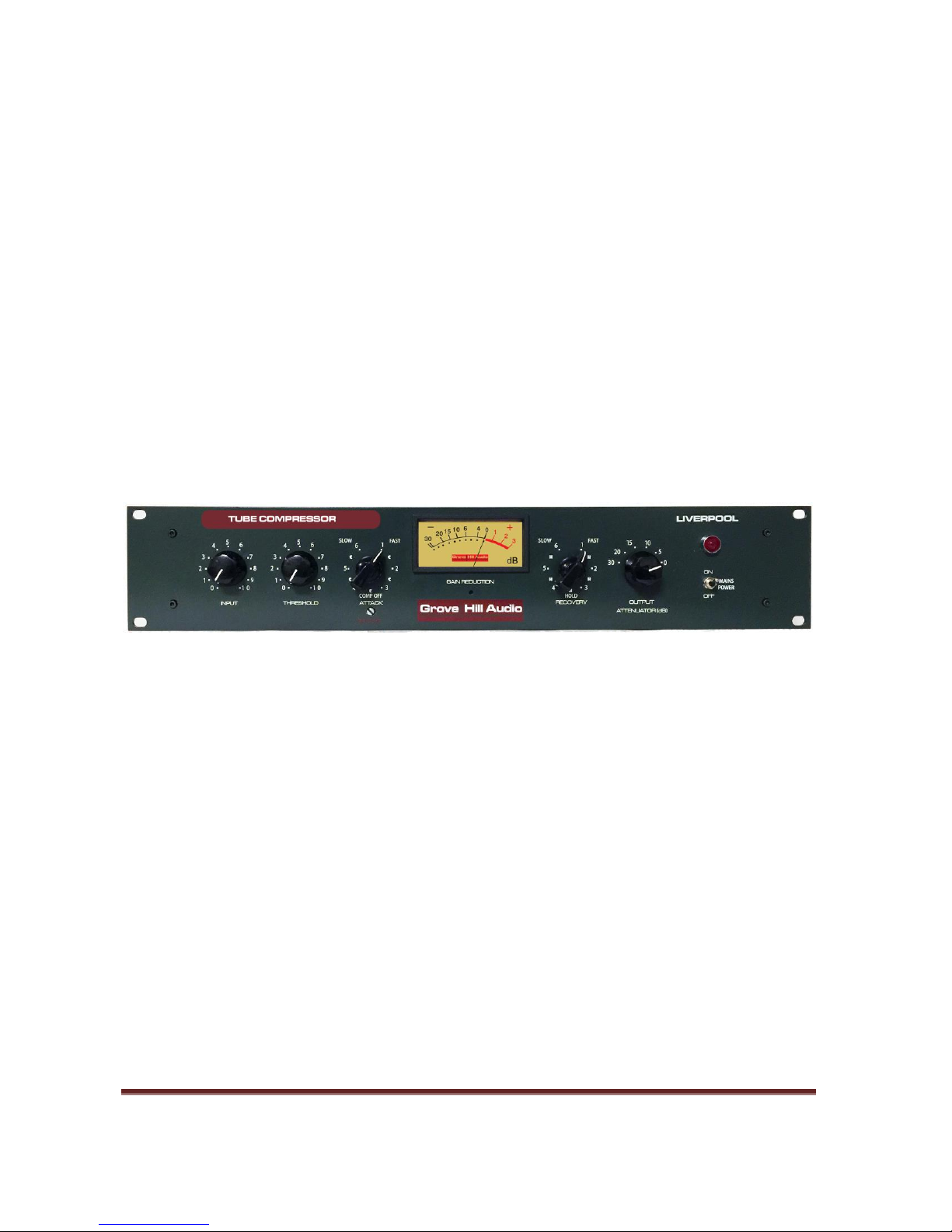
on the compression meter. The input control on the LIVERPOOL is located
ahead of the tubes and directly after the input transformer. So as you
advance the input control, you're hitting the input tube, which is the gain
reduction stage, with more and more signal. The signal is then amplified
by the second stage. The control signal is taken from the output of the
second stage then rectified into a negative control voltage (CV). Gain
reduction is done by making the DC bias on the first stage tube more
negative. So as the input is increased so does the CV and therefore the
amount of compression. The onset of compression is determined by the
threshold and how far the input control is advanced. The input tube has a
limit as to how far it can be biased negative to reduce gain before it goes
non-linear, and since your audio signal is obviously swinging both positive
and negative, the big swings of the audio signal plus the negative gain
control voltage will eventually push the tube into cut off. The limiting
characteristics shouldn't change much, but the distortion characteristics
will. Distortion can be creatively used by turning up the Input and turning
down the Output while using very little or no compression.

LIVERPOOL Tube Compressor Page 10
2. Threshold Control:
The threshold control determines how much compression takes place and
the output level at which compression commences. The threshold also
adjusts the ratio.
3. Attack Control:
The attack controls how much of the signal transient is allowed through
before compression starts. There are 6 different speeds labelled 1 (Fast)
to 6 (Slow) with every second selection, labeled ‘C’, turning off the
compression action. In these positions, the unit can be used as a line
amplifier.
Attack times
1 –3 milliseconds
2 –19 milliseconds
3 –48 milliseconds
4 –77 milliseconds
5 –109 milliseconds
6 –138 milliseconds
4. Recovery Control:
The recovery control determines how quickly the signal rebounds after
the input signal has fallen below the threshold. There are six Recovery
positions labelled 1 (Fast) to 6 (Slow) with every second selection turning
on the ‘H’ HOLD function.

LIVERPOOL Tube Compressor Page 11
Recovery times
1 –127 milliseconds
2 –447 milliseconds
3 –917 milliseconds
4 –1.9 seconds
5 –3.4 second
6 –6 seconds
The Hold function is a unique feature of the compressor. It was added as a
modification on the original compressor in response to two scenarios
faced by engineers when large amounts of gain reduction are being
applied:
1. When trying to process the initial attack of an audio track, the
slow attack of the compressor will cause an audible thump to be
produced. The Hold control would be used in these cases to “prime” the
compressor with the required amount of gain reduction and prevent the
thump from occurring. This was done by playing a track into the
compressor, setting the controls as required and then moving the
Recovery control to one of the adjacent Hold positions. This would
prevent the compressor release taking place and maintain the amount of
gain reduction.

LIVERPOOL Tube Compressor Page 12
The track can then be stopped, moved back to the beginning of the track
and playback started again. Once the initial attack of the first note has
been processed, the compressor can be switched out of Hold and put back
to the desired Recovery setting.
2. If the unit is compressing a track with room ambience, the
ambient noise from the recording would swell up in volume at the end of
the performance as the gain reduction returned from the compressed
level to zero. This can be avoided by switching the Recovery control to an
adjacent Hold position after the last note has finished, which would stop
the compressor release from taking place.
5. Output Attenuator:
The output attenuator is a six position rotary switch. This method of
attenuation allows for constant impedance on the output transformer as
well as the load. The attenuator gives you output gain control of your
signal output into the next device in the chain. The selections are: 0dB, 5
dB, 10dB, 15dB, 20dB and 30dB of precise output signal attenuation.
6. Mains Power Switch
The power switch is used to turn the compressor on or off.

LIVERPOOL Tube Compressor Page 13
7. Cathode Balance
The cathode balance pot is used to balance the cathodes of the Mu
tube. This helps to reduce thumps and instability. To adjust the
cathode balance turn the pot fully CW and then fully CCW then to the
middle position. Connect the negative lead of a digital multi meter to
ground and the other one to test pin 3 of the tube socket and note the
voltage, then measure the voltage at test pin 8 of the same socket.
Adjust the pot until the voltage at pin 3 and 8 are equal. You should
not have to perform this calibration again unless this tube is changed.
8. Anode Balance
The anode balance pot is used to balance the anodes of the Mu tube.
This helps to reduce thumps and instability. To adjust the anodes
balance turn the pot fully CW and then fully CCW and then to the
middle position. Connect the negative lead of a digital multi meter to
ground and the other one to test pin 1 of the 6BC8 tube socket and
note the voltage, them measure the voltage at test pin 6 of the same
socket. Adjust the pot until the voltage at pin I and 6 are equal. You
should not have to perform this calibration again unless the tube is
changed.
9. G.R. Zero Adjust
The GR zero is used to adjust the meter to show zero gain reduction
when the unit is at rest. Allow the unit to warm up for 15 - 20 minutes,
and then adjust the pot until the meter reads zero
.
This adjustment
need only be done when replacing the Mu tube.

LIVERPOOL Tube Compressor Page 14
TECHNICAL NOTES
SWITCHING ON
The power switch is located on the right side of the front panel. Flip the
switch up to turn on the LIVERPOOL compressor and down to turn it off.
Do not operate this switch up and down rapidly, as it may cause damage.
TUBE LIFE
As with all tubes, their quality degrades with age. This is due to cathode
emission, a natural process found in all tubes. We recommend that you
have your unit checked every 4-5 years, depending on usage. One
symptom of failing tubes is increased noise floor and performance
changes.
NOTE
Allow the LIVERPOOL to warm up before operating. This unit employs
high voltage tubes and reaches optimum operation within approximately
twenty minutes. Any adjustments such as meter calibration should be
performed when the unit had time to warm up to operating temperature.
OPERATION
The principle of operation of this unit is based around a Mu tube, an all
glass miniature VHF dual triode, remote cut-off tube. This is the gain
reduction tube. This tube is re-biased by the 6AL5 vacuum tube rectified
side-chain control voltage which causes the Mu tube to smoothly change
its mutual conductance. The benefits of utilizing a variable mutual
conductance vacuum tube as the 'heart' of the compression function is
that a widely varying range of input signals can be handled quickly
without introducing harmonic distortion.
As with all compressors there will be little change of gain reduction with
various settings of ATTACK and RECOVERY controls using a sine wave
source. With music there will be changes in the amount of gain reduction
with changes of these controls.

LIVERPOOL Tube Compressor Page 15
HUM
This unit is meant to use the third pin of the mains as the ground
reference. The GROUND TERMINAL is one method to reduce hum. Verify
that the terminal is connected with the ground strap or that the hum is
less with the strap off of the terminal. If that does not work, try a three pin
to two pin AC adapter for the AC plug.
The most common problem is the input/output cabling. Transformer
isolated balanced inputs and outputs are most immune to ground
problems. These balanced inputs and outputs will interface to unbalanced
inputs and outputs automatically. This is a prime benefit with
transformers.
Alternative ground schemes are common in studios. The two most used
are cutting shields at either inputs or outputs to prevent ground loops and
star grounding style. This method does not use any AC grounds but
supplies a separate ground wire from a central ground to each piece of
gear.
CHASSIS GROUND may be connected to the rack rails or not. Always try to
use pro gear that is designed to drive 600 ohms for this unit.
Another source of hum can be equipment mounted on top of one another.
This is not a good for hum or ventilation and should be avoided.

LIVERPOOL Tube Compressor Page 16
SERVICE ADJUSTMENTS
The internal chassis has high voltage present which can cause harm or
even death.
Do not attempt to make these service adjustments.
Have a qualified technician perform these tasks.
These are factory presets and need only be altered after a re-tube or if a
change in performance is suspected.
1. Cathode Balance –Refer to item number 7 in the “Operation and Use
of Controls” section.
2. Anode Balance - Refer to item number 8 in the “Operation and Use
of Controls” section.
3. Gain Reduction Zero Adjust - Refer to item number 9 in the
“Operation and Use of Controls” section.

LIVERPOOL Tube Compressor Page 17
Specifications:
Type: Tube Compressor Amplifier
Frequency Response: +/- 1.5dB, 10 Hz to 40,000Hz
Frequency Response (vintage): +/- 1.5dB, 300 Hz to 15,000Hz
Power Output: +20 dBm
Total Harmonic Distortion: 0.08% at 1 KHz with output at 0dB
Noise Level: 82 dBu below rated output
Source Impedance: Any up to 15,000 Ohms
Load Impedance: 600 Ohms
Attenuation: 30 dB in 5 dB steps - Constant impedance.
Maximum Compression: 30dB
Attack Times (*msec): 3*, 19*, 48*, 77*, 109*, 138*.
Recovery Times (*msec): 127*, 447*, 917*, 1.9 sec., 3.4 sec., 6 sec.
Threshold: 0dBm to +16dBm Output
Compression Ratios: 2:1 at 0dBm Threshold, 4:1 at +16dBm
Threshold
Tube Complement: 6BC8/6BZ8 or approved equivalent, 6CG7, 6AL5
Specifications are subject to change without notice.

LIVERPOOL Tube Compressor Page 18
Tube Substitution*:
The following tubes can be substituted by a qualified technician.
The 6BC8 can be substituted with a 6BC8, 6BZ8, ECC189, 6N1-P or PCC189.
The 6AL5 can be substituted with an EAA901S, D77, EB91, 5726 or 6058.
Substitution of the 6CG7 is not recommended.
*Although substitute tubes will perform well, for optimum results use
the same model tubes as supplied.

LIVERPOOL Tube Compressor Page 19
Warranty
All Grove Hill Audio equipment is covered by a limited warranty against
defects in materials and workmanship for a period of 90 days from date of
purchase to the original purchaser only. A further 270 day warranty is
available to the original purchaser upon proper registration of ownership
within 30 days of date of first purchase.
Proper registration is made by filling out and returning to the factory the
warranty registration sheet, attached to this general warranty statement,
along with a copy of the original sales receipt as proof of the original date of
purchase. Only one sheet is issued with each unit, and copies will not be
accepted.
If the warranty registration sheet has already been removed then this is not a
new unit, and is therefore not warranted by the factory. If you believe this to
be a new unit then please contact the factory with the details of purchase.
This warranty is provided by the dealer where the unit was purchased, and by
Grove Hill Audio, LLC. Under the terms of the warranty defective parts will be
repaired or replaced without charge, excepting the cost of tubes. No warranty
is offered on tubes, unless the warranty registration sheet is completed.
If a Grove Hill Audio product fails to meet the above warranty, then the
purchaser's sole remedy shall be to return the product to Grove Hill Audio,
where the defect will be repaired without charge for parts and labor. The
product will then be returned via prepaid, insured freight, method and carrier
to be determined by Grove Hill Audio. All returns to the factory must be in the
original packing, (new packing will be supplied at a nominal cost if needed),
accompanied by a written description of the defect, and must be shipped to
Grove Hill Audio via insured freight at the customer's own expense.

LIVERPOOL Tube Compressor Page 20
Charges for unauthorized service and transportation costs are not
reimbursable under this warranty, and all warranties, express or implied
become null and void where the product has been damaged by misuse,
accident, neglect, modification, tampering or unauthorized alteration by
anyone other than Grove Hill Audio.
The warrantor assumes no liability for property damage or any other
incidental or consequential damage whatsoever which may result from failure
of this product. Any and all warranties of merchantability and fitness implied
by law are limited to the duration of the expressed warranty. All warranties
apply only to Grove Hill Audio products purchased and used in the United
States of America.
Some states do not allow limitations on how long an implied warranty lasts, so
the above limitations may not apply to you. Some states do not allow the
exclusion or limitation of incidental or consequential damages, so the above
exclusion may not apply to you.
This warranty gives you specific legal rights and you may also have other
rights which vary from state to state.
Table of contents