Growonix BP-1530 User manual

BP-1530
Booster Pump
Owners Manual
www.growonix.com
Built in the U.S.A.

INCREASES PURE WATER PRODUCTION FOR ALL RO SYSTEMS 600 GPD AND
UNDER.
RAISES THE INPUT PRESSURE TO 80PSI.
CAN SIPHON FROM A RAIN BARREL OR TANK AND PRODUCE THE FULL PUMP
PRESSURE.
NEEDS ZERO PSI OF INCOMING WATER PRESSURE TO PRODUCE THE FULL FLOW
RATE.
HIGH PRESSURE CUTOFF—AUTOMATICALLY SHUTS THE PUMP OFF WHEN USED
WITH A SOLENOID VALVE, BALL VALVE, FLOAT VALVE, OR WATERING WAND ETC...
WHY USE A GROWONIX BP-1530?
MOUNTING
2
• To raise the water pressure on a water lter.
• To supply a misting system.
• To raise the pressure on any water appliance that ows up to 1 GPM @ 80psi.
• To bilge out water from a tank or reservoir.
• To supply a faucet, shower, or hose bib (MAX 1GPM).
CONNECT MULTIPLE IN PARALLEL AND DOUBLE THE FLOW RATE!
FEATURES
Part # In / Out Voltage Amps Flow
Rate
High
Pressure
Cutoff Duty Cycle FITS
BP-1530 3/8” tube 120 VAC 2 1 GPM Yes Intermittent
All systems 600 GPD & under

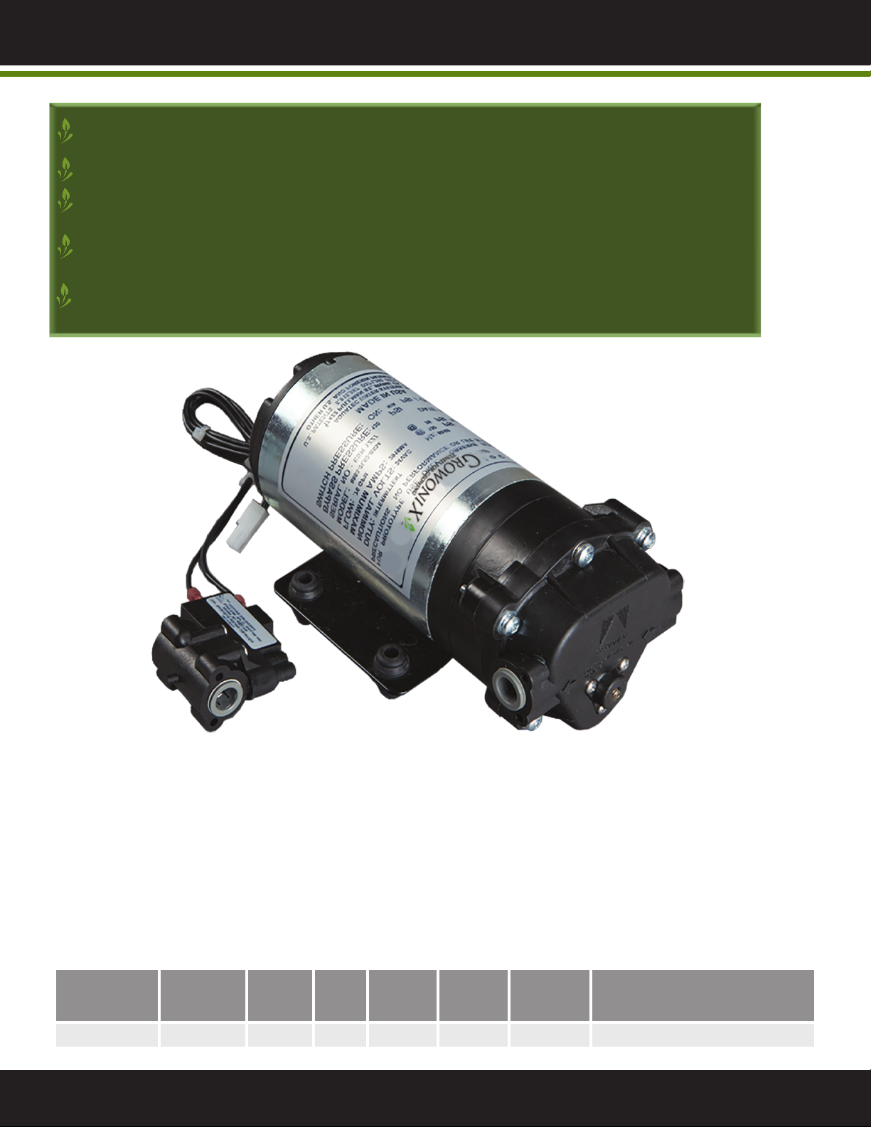
• The BP-1530 Booster Pump is designed for use with all GrowoniX water lters 600 GPD and under.
• The pump is designed to boost low water pressure to optimal pressure.
• Do not exceed 79 psi output pressure.
ABOUT
CAUTIONS
MOUNTING
• The pump is equipped with an adjustable bypass valve which controls the maximum operating
pressure. In addition, never subject the pump to pressures above 80 PSI.
• Never operate the pump in a harsh environment or hazardous atmosphere,
since motor brush and switch may cause electrical arcing.
• Pumphead materials are designed for use with water only. Do not use with petroleum products.
• Always consider electrical shock hazard when working with and handling electrical equipment.
If uncertain, consult an Electrician. Electrical wiring should only be done by a qualied Electrician
per Local and State Electrical Codes.
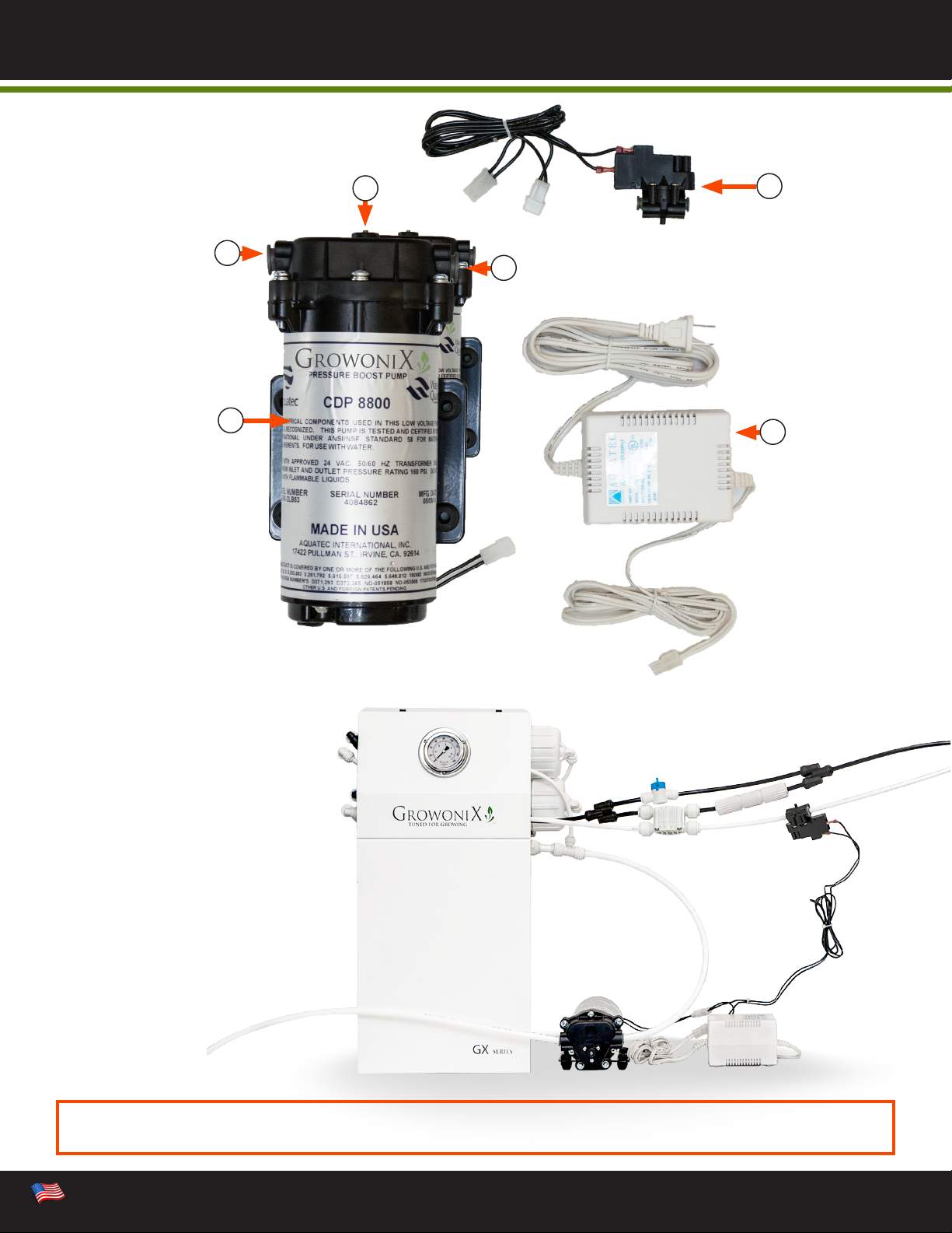
• The pump should be mounted in a dry place and away from any source of heat. If an enclosure is
used, special provisions for cooling the motor may be necessary. Consult the Factory.
• Do not subject the pump to extreme high or low (freezing) temperatures while in operation.
(Operating ambient temperature range is 32ºF to 115ºF).
• The pump may be mounted in any position. If “ceiling mounted”, however, with the pumphead
upside down, air entrapment may reduce the operational performance by up to 15%.
READ ENTIRE MANUAL THOROUGHLY
BEFORE INSTALLING THIS HIGH PRESSURE-BOOSTING PUMP.
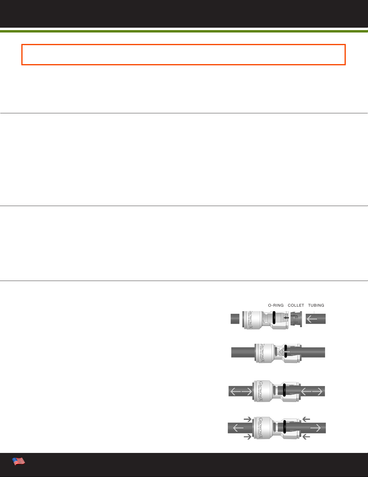
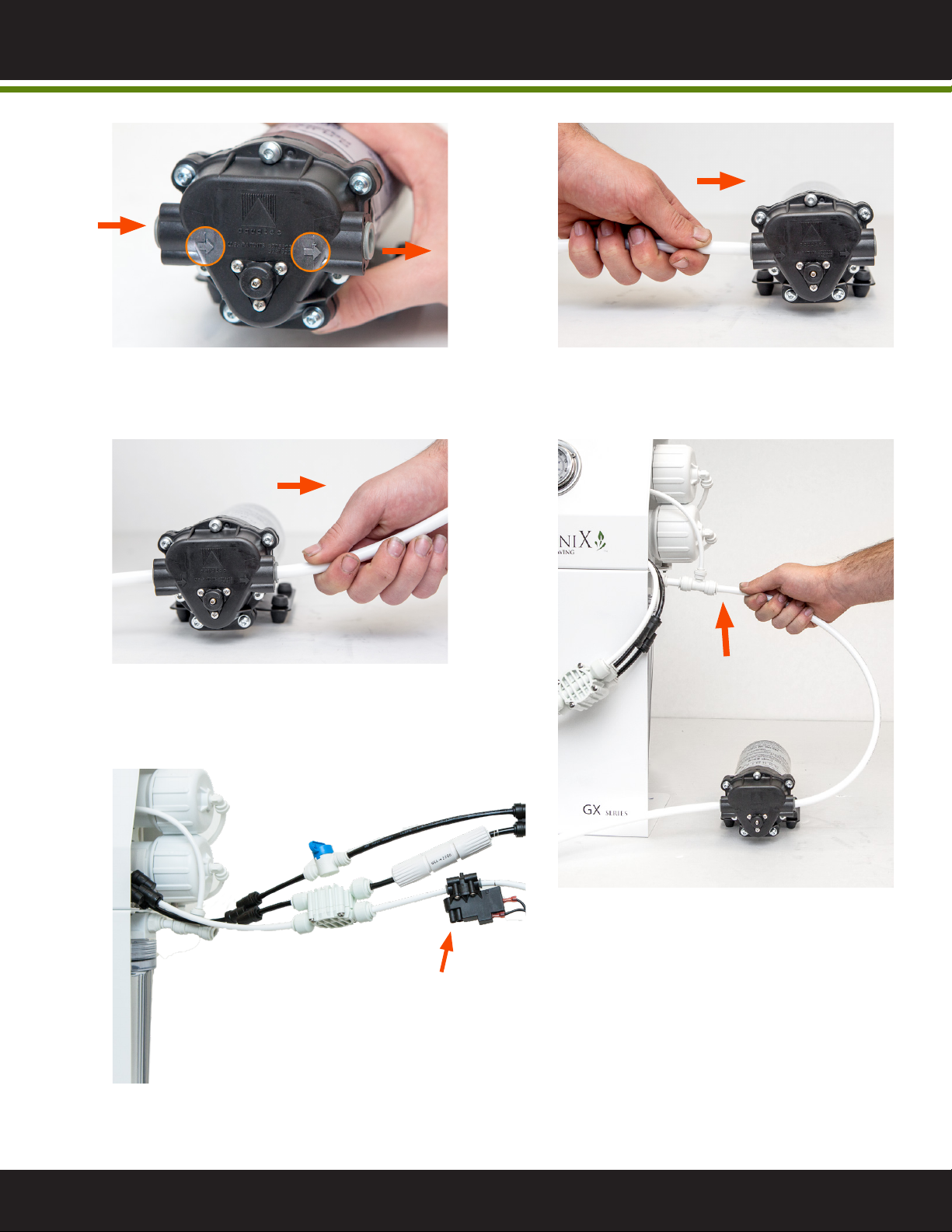
INSERT TUBE INTO FITTING
Push the tubing through the collet and dual o-rings until it bottoms
out against the tube stop.
The collet holds the tube in place and the dual o-rings provide a leak
resistant seal.
MAKE A CLEAN TUBE CUT
Cut the tube squarely and if using plastic tubing, ensure that the cut has
not made the tube out of round.
Also ensure that the tube has a smooth outside diameter without any
burrs or score marks prior to inserting it into the tting.
TEST AND INSPECT
Push and pull the tubing toward and away from the tting to ensure
that it has been installed properly.
Test and inspect the installation for any leaks.
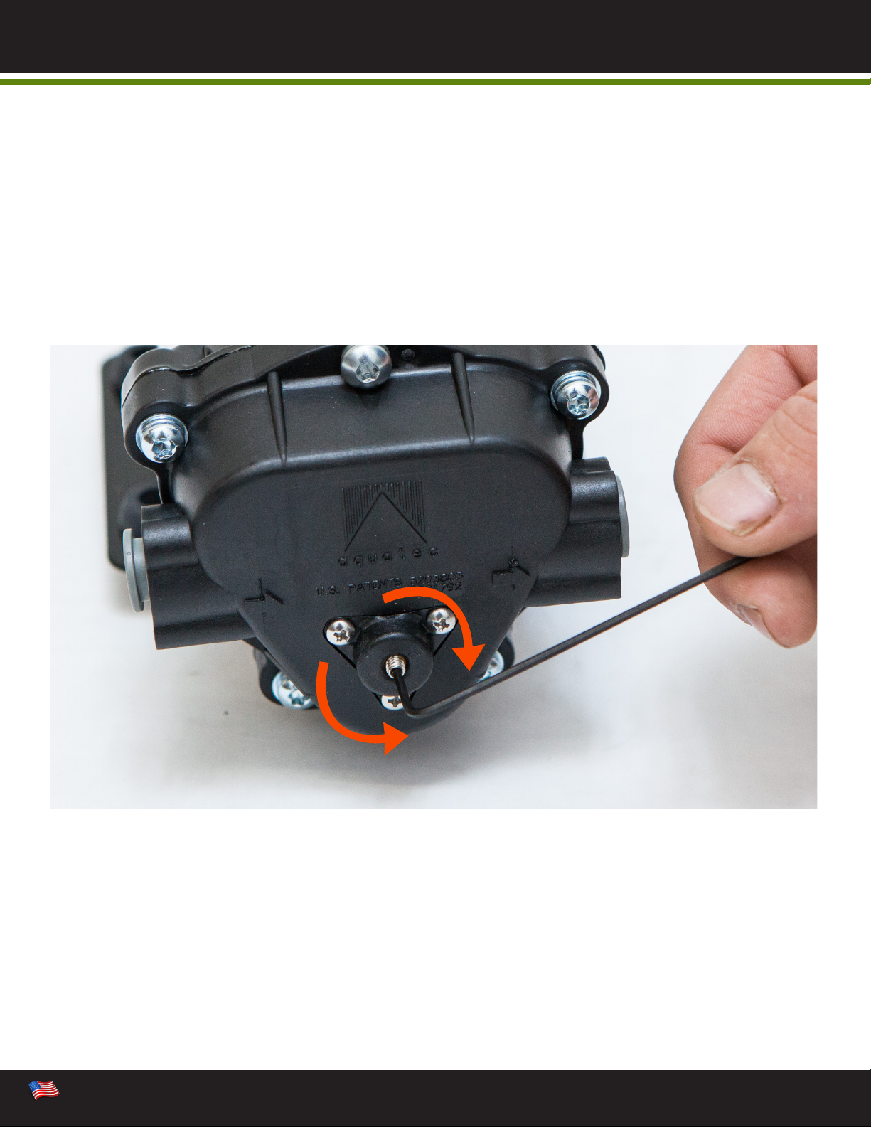
TUBE REMOVAL
Relieve pressure from the tubing and tting. Push uniformly around
the collet ange against the tting body while pulling the tubing away
from the tting to release it.
O-RING
COLLET
TUBING
PUSH COLLET IN PULL TUBE OUT
GROWONIX WATER FILTERS USE QUICK CONNECT FITTINGS
THAT ALLOW FOR EASY MAINTENANCE.
3
Built in the U.S.A.Built in the U.S.A. 3
BASIC INFORMATION

The motor is available in 110 and 50/60 hertz 1 phase 2A. Please ensure that the electrical
circuit supplying the system is compatible with the requirements of the BP-1530 pump. Each BP-1530
pump is equipped with an 5” electrical cord.
TO REDUCE THE RISK OF ELECTRICAL SHOCK, THE INCOMING POWER SUPPLY MUST INCLUDE
A PROTECTIVE EARTH GROUND.
Pump will prime only if all pressure is relieved from the outlet port.
It is recommended that an in-line sediment lter (150 micron or 100 mesh) be installed at the inlet
side to keep foreign debris out of the system.
Avoid any sharp bends which may crimp tubing and restrict ow. Use 90º elbow ttings if necessary.
Carbon lters should be ushed prior to connectivity to prevent carbon particles from entering the
pump chambers, and possibly causing clogging.
• The input is 3/8” OD” quick connect tubing.
• The output is 3/8” OD quick connect tubing.
PLUMBING
CAUTION
ELECTRICAL
NOTE
WARNING
READ ENTIRE MANUAL THOROUGHLY
BEFORE INSTALLING THIS HIGH PRESSURE-BOOSTING PUMP.
Any restrictions or blockage in the drain line of the RO system can cause back pressure, which will
increase the systems operating pressure. this can result in damage to the system’s membranes and
components and a potentially DANGEROUS OVERPRESSURIZATION CONDITION.
We recommend use of exible tubing with proper pressure rating.
4
PLUMBLING AND ELECTRICAL
WE RECOMMEND THAT A LICENSED ELECTRICIAN WIRE YOUR SYSTEM IN ACCORDANCE WITH
LOCAL AND NATIONAL ELECTRICAL CODES (NEC).

READ ENTIRE MANUAL THOROUGHLY
BEFORE INSTALLING THIS HIGH PRESSURE-BOOSTING PUMP.
1
32
6
5
4
1. Motor
2. Pump Input
3. Pump Output
4. Adjustable Internal Bypass
5. Pressure Switch
6. Power Transformer
5
Built in the U.S.A.Built in the U.S.A. 5
COMPONENT DIAGRAM

2
4
5
1
3
Input
Input
Output
Output
Make note of direction of ow prior to
installation.
Connect the 3/8” feed water tubing to
the pump input.
Insert another piece of 3/8” tubing into
the pump output.
Insert the 3/8” pump output tubing into
the RO lter input.
Install the pressure switch on the product water line (RO out tubing) after the auto-shuto valve. The
switch can be installed in any direction.
Pressure
Switch
(PSW)
6
SETUP INSTRUCTIONS

The BP-1530 Booster Pump is equipped with an adjustable internal bypass valve, which controls the
maximum operating pressure. The valve is located in the center of the triangular cap on the top of the
pump head, between the input and output ports. To adjust, insert the included 1/16” Allen Wrench into
the chrome adjustment screw. Turn clockwise to increase operating pressure. Turn counter-clockwise
to decrease operating pressure. It is recommended not to exceed 79 psi operating pressure.
Turn clockwise to INCREASE operating pressure.
Turn counter-clockwise to DECREASE operating pressure
DECREASE
INCREASE
Increase
Reference the pressure guage on front of the RO lter while adjusting the pump pressure.
7
Built in the U.S.A.Built in the U.S.A. 7
ADJUSTABLE INTERNAL BYPASS

www.growonix.com toll free 888.406.8521, oce 818.510.0264, sales@growonix.com
For a period of one year from the date of original purchase, we will replace or repair any part of the GrowoniX
product that we nd to be defective in operation due to faulty materials or workmanship with the exception of
the replaceable lters and membranes.
GENERAL CONDITIONS
Damage to any part of this product because of misuse; misapplication; negligence; alteration; accident;
installation; or operation contrary to our instructions, incompatibility with accessories not installed by GrowoniX,
or damage caused by freezing, ood, re, or Act of God, is not covered by this warranty. In all such cases,
regular charges will apply. This limited warranty does not include service to diagnose a claimed malfunction in
this unit. This warranty is void if the claimer is not the original purchaser of the unit or if the unit is not operated
under normal municipal water or well water conditions.
GrowoniX assumes no liability in connection with this product. GrowoniX assumes no liability for any damages
incurred through the use of this product. It is the responsibility of the end user to gauge the safe use of this
product in the environment where it is applied. We do not authorize any person or representative to assume for
us any other obligations on the sale of this reverse osmosis system. The information given out in the manual
we believe to be true, but are oered to you in good faith without guarantee because each application of this
product is dierent and beyond our control.
GROWONIX RETURN POLICY
MERCHANDISE RETURN DETAILS AND PROCEDURE:
If any merchandise was defective —we will refund the full purchase price upon receiving and reviewing the
merchandise returned in undamaged condition.
RMA NUMBER:
You must rst obtain a Return Merchandise Authorization (RMA) number from GrowoniX.com. Any products
sent to GrowoniX without an RMA number will not receive a refund and may be returned to the sender at their
expense.
All refund amounts will be based on the manufacturer’s warranty and GrowoniX return policy. Refunds will be
issued back using the payment method you used when you placed your order. Refunds take up to 3-5 business
days to process once we receive the return.
PACKAGING:
Please kindly re-pack the product in its original box, or a box of equivalent strength. The unit should be packed
in the same manner as it came to prevent damage in shipping. Please return everything that was in the original
box, including any free items if applicable. Be sure to drain out all water from wet systems and parts and wrap
them in plastic bags before packing.
RETURN TO:
We will provide you with an GrowoniX warehouse address for return merchandise when we issue the RMA number.
GROWONIX SYSTEM WARRANTY
Other manuals for BP-1530
1
Table of contents
Other Growonix Water Pump manuals