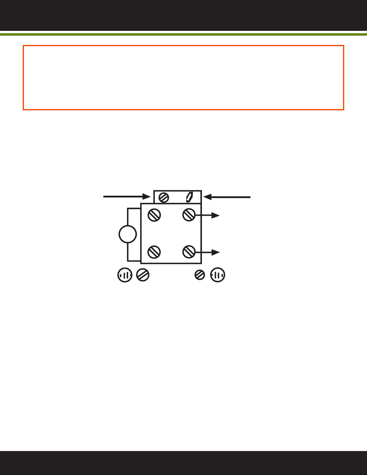
WATER PUMP PRESSURE SWITCH
Turn clockwiseto increase
cut-out pressure, without
affecting cut-in.
PRESSURE SWITCH HAS ONLY TWO ADJUSTMENT TERMINALS
WATER PUMP PRESSURE SWITCH ADJUSTMENT
Series CXA Water Pump Pressure Switch
Specifications - Installation and Operating Instructions
Bulletin IN-525A
INSTALLATION/MOUNTING
The switch can be pipe mounted in any position. Do not twist the
case when installing. Use a wrench on the pressure connection
flats.
WIRING
All wiring must conform to the National Electrical Code and local
regulations. Do not install the control to handle loads in excess of
electrical rating shown in specifications or as indicated on
instructions inside control cover.
TURN
CLOCKWISE
TO INCREASE
BOTH CUT-OUT
AND CUT-IN
PRESSURE
TURN
CLOCKWISE
TO INCREASE
CUT-OUT
PRESSURE
WITHOUT
AFFECTING
CUT-IN
MOTOR
LINE
LINE
POWER
SUPPLY
MOTOR
M
WIRING DIAGRAM
SPECIFICATIONS
Service: Compatible liquids and gases.
Wetted Materials: Silicone, steel, and SS.
Temperature Limits: 140°F (60°C).
Pressure Limits: See model chart.
Enclosure Rating: General purpose.
Repeatability: ±5 psig (±0.3 bar).
Switch Type: SPST snap action (see model chart).
Electrical Ratings: 20A @ 120 VAC, 12A @ 240 VAC, 9.6A @
240 VAC (3 phase), 8.6A @ 32 VDC, 3.1A @ 120 VDC, 1.6A @
240 VDC.
Electrical Connections: Screw terminal.
Conduit Connection: 7/8˝ hole for 1/2˝ conduit hub (2 places).
Process Connection: 1/4˝ female NPT.
Mounting Orientation: Switch can be installed in any position.
Setpoint Adjustment: Internal screws.
Weight: 0.75 lb (0.34 kg).
Deadband: See model chart.
Agency Approvals: CE, UL pending.
CAUTION: No lubrication or periodic servicing is required. Mount
the control securely. Never exceed the electrical rating for the
switch. Use the control only with compatible medias.
MAINTENANCE
Upon final installation of the Series CXA Water Pump Pressure
Switch, no routine maintenance is required. A periodic check of
the system calibration is recommended. The Series CXA is not
field serviceable and should be returned if repair is needed (field
repair should not be attempted and may void warranty). Be sure to
include a brief description of the problem plus any relevant
application notes. Contact customer service to receive a return
good authorization number before shipping.
©Copyright 2006 Dwyer Instruments, Inc. Printed in U.S.A. 11/06 FR# R3-443463-00
MERCOID DIVISION
DWYER INSTRUMENTS, INC.
P.O. BOX 258 • MICHIGAN CITY, INDIANA 46361 U.S.A.
Phone: 219/879-8000 www.dwyer-inst.com
Fax: 219/872-9057 e-mail: info@dwyer-inst.com
The Series CXA Water Pump Pressure Switches have been
proven reliable for controlling automatic water systems. These
switches are very popular for use on water well pumps and
pumping systems. The set point and deadband are both easily
adjustable via screws inside the cover. For ease of installation, the
switches come with a 1/4˝ female NPT process connection and
can be mounted in any orientation. The series CXA’s simple design
makes it a great switch for an installer at any skill level.
MODELS
Max.
Pressure
psig (bar)
129 (8.9)
179 (12.3)
204 (14.1)
129 (8.9)
179 (12.3)
204 (14.1)
Switch
Type
NC
NC
NC
NO
NO
NO
Model
Number
CXA-S1
CXA-S2
CXA-S3
CXA-R1
CXA-R2
CXA-R3
Range
psig (bar)
15-80 (1.0-5.5)
30-100 (2.1-6.9)
35-150 (2.4-10.3)
15-80 (1.0-5.5)
30-100 (2.1-6.9)
35-150 (2.4-10.3)
Approx.
Adjustable
Deadband
psig (bar)
15-30 (1.0-2.1)
20-35 (1.4-2.4)
30-40 (2.1-2.8)
15-30 (1.0-2.1)
20-35 (1.4-2.4)
30-40 (2.1-2.8)
2-17/64
(57.6)
3-3/8
(85.5)
3-45/64
(94)
2-9/16
(65)
* *
THE PUMP MUST NEVER BE RUN DRY. OPERATING THE PUMP WITHOUT SUFFICIENT FEED
WATER WILL DAMAGE THE PUMP.
ALWAYS FEED THE PUMP FILTERED WATER. THE PUMP IS SUSCEPTIBLE TO DAMAGE FROM
SEDIMENT AND DEBRIS.
IF ANY DAMAGE OCCURS TO YOUR SYSYTEM’S PUMP, A RE-BUILD KIT MAY BE AVAILABLE.
CONTACT YOUR LOCAL DEALER OR DISTRIBUTOR AND INFORM THEM OF YOUR SYSTEM’S
MODEL AND PUMP SIZE.
• The pump is a low-lead brass rotary vane pump.
• This pump is also available in stainless steel.
• Follow these guidelines to ensure proper operation of the pump:
The low pressure switch shuts o the system when the feed water pressure drops too low for the
system to function properly. This prevents damage to the pump. The system restarts automatically
when the pressure is restored. If you notice the pressure uctuating, and the system cycling o and
on repeatedly, turn the system o and ensure that proper feed ow and pressure are available to the
system.
The water pump pressure switch is adjusted at the factory to cut out when incoming pressure falls
below 10 psi, and cut in when incoming pressure reaches 25 psi.
PRESSURE SWITCH SHOULD NOT NEED ADJUSTMENT.
If for some reason pressure switch should fall out of adjustment, follow the diagram above. Factory
settings are:
Terminal 1 adjusted fully counterclockwise.
Terminal 2 adjusted fully counterclockwise.
1 2
7
6Built in the U.S.A.
Turn clockwise to increase
both cut-out and cut-in
pressure.
BP-6010 INFORMATION