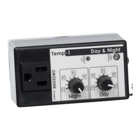
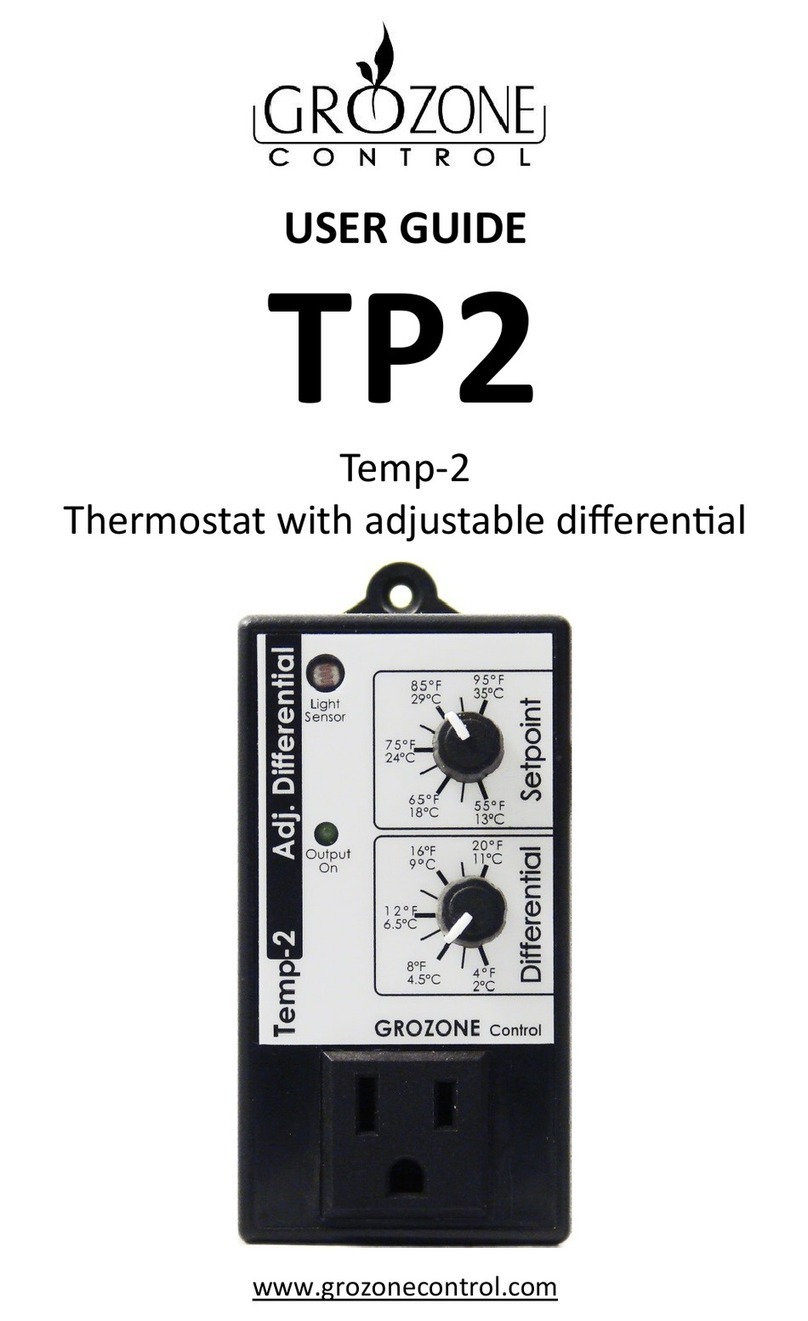
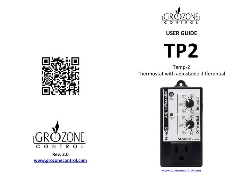
Grozone Control TP3 User manual

www.grozonecontrol.com
USER GUIDE
TP3
Temp-3
High Temp Shut Off

TABLE OF CONTENTS
SAFETY NOTICE 3
INSTALLATION & OPERATION 4
OPTIONAL SETTINGS/5°F COOLDOWN 5
OPTIONAL SETTINGS/10°F COOLDOWN 6
QUICK TROUBLESHOOTING GUIDE
COMPLETE TROUBLESHOOTING GUIDE 8-9
WARRANTY & CUSTOMER SERVICE 10-11
PRODUCT DETAILS 12

3
SAFETY NOTICE
IMPORTANT SAFETY INSTRUCTIONS
SAVE THESE INSTRUCTIONS
DANGER
TO REDU E THE RISK OF FIRE OR ELE TRI SHO K,
AREFULLY FOLLOW THESE INSTRU TIONS.
To reduce the risk of electric shock, disconnect power to the 120V
electrical outlet before installing or removing the unit. When removing the
electrical wall plate, it may fall across plug pins or become displaced.
To reduce the risk of electric shock, this product has a grounding type plug
that has a third (grounding) pin. This plug will only fit into a grounding
type power outlet. If the plug does not fit into the outlet, contact a
qualified electrician to install the proper outlet. Do not change the plug in
any way.
3

4
INSTALLATION & OPERATION
Note: This unit has been set to perform 10°F setback. For 5°F setback,
refer to Optional settings.
Set Values
Plug into 120 VA outlet (see security notice on page 1).
Place the sensor at desired location.
onnect the sense cord from light switcher into the front panel outlet.
High Temp
Installation is now complete
Start delay
Note: If TP3 is plugged into a 24h timer, deduct start delay from
24H timer start program (start time).
4

5
A. Unplug the unit.
Set both values to maximum.
OPTIONAL SETTINGS/5°F COOLDOWN
B. Within 5 seconds, plug in
the unit, then set both
values to minimum.
C. "Output On" light indicator
turns On or Off according to
actual setting.
TP3 is now in 5°F cool down
Change to 5°F cooldown
5

6
A. Unplug the unit.
Set both values to minimum .
B. Within 5 seconds, plug in the
unit, then set both values to
maximum.
C. "Output On" light indicator
turns On or Off according to
actual setting.
TP1 is now in cooling mode
OPTIONAL SETTINGS/10°F COOLDOWN
Change to 10°F cool down
6

7
QUICK TROUBLESHOOTING GUIDE
Quick Troubleshooting Chart
Product Model
: TP3
PLUG UNIT INTO 120V
PLUG LOAD INTO OUTPUT*
DEFINITIONS
Min : Knob at 70°F or below
Max : Knob at 120°F or above
•
Start delay at 0
minute
•
Temp Probe in hand
palm
*Before test, check if load is working properly.
High temp
Knob at
Min
Product
Defective
Product
Defective
Start delay at 10 minutes
High temp
knob at
Max
High temp
knob at
Min
Product
Defective
High temp
knob at
Max
Start
delay at
0 minute
Output On
Product
Defective
Output
Off
Product
Defective
Product
Good
= Steps
A
B
D
E
F
Output
On
Output On
Output
On
Output Off
Output Off
Output
On
Output
Off
Output
7

8
COMPLETE TROUBLESHOOTING GUIDE
High Temperature Shut-Off
TP3
1 – Before you start
2 – Test
***IMPORTANT: READ AND FOLLOW THESE INSTRUCTIONS BEFORE
STARTING THE TEST.
•
DO NOT ONNE T UNIT BEFORE STEP 1 OF THE TEST.
•
DO NOT ONNE T A LOAD INTO THE UNIT BEFORE STEP 3 OF THE TEST.
•
TEMPERATURE: You have to perform this test with the sensor held in
the palm of your hand to simulate a temperature between 30° and
40° (86°F and 104°F).
•
Definitions : W : lockwise.
W : ounter clockwise.
STEP HANDLING AND TEST DESCRIPTIONS EXPECTED RESULTS
1
•
Plug the unit into the power outlet
while maintaining the temperature
sensor in your hand.
Within 5 seconds:
•
Turn UPPER knob fully W (High
Temp at 120°F).
•
Turn LOWER knob fully W (Delay
at 0 min.).
Output On light
indicator turns ON.
8

9
COMPLETE TROUBLESHOOTING GUIDE
STEP HANDLING AND TEST DESCRIPTIONS EXPECTED RESULTS
2
•
Turn UPPER knob fully W. Output On light
indicator turns OFF.
3
WITHDRAW THE SENSOR FROM YOUR
HAND :
•
Set the LOWER knob one line over 0
(Delay at 1 min.).
•
Turn UPPER knob fully W.
•
Plug a load into the TP3 front outlet.
•
WAIT approximately 1 minute.
Output On light
indicator and the load
turn OFF instantly and
they will turn back ON
after ONE MINUTE.
Make sure that the
load ON/OFF switch (if
any) is ON.
9

10
WARRANTY & CUSTOMER SERVICE
DO YOU HAVE A PROBLEM WITH YOUR ONTROLLER ? PLEASE READ
THESE INSTRUCTIONS CAREFULLY AND SAVE THEM FOR FUTURE
REFERENCE.
1. I think my controller is damaged, or it simply does not work as
indicated in the user guide, what should I do?
•
Please refer to the troubleshooting steps. Follow these instructions
carefully, step by step. The controller should work as described in the
“Expected results” column of the omplete Troubleshooting Guide.
Do you need assistance on executing the Troubleshooting steps?
1. Contact us at 1-855-262-1800
2. Send us an EMAIL at service@grozonecontrol.com
3. VISIT our Technical Support Center at
www.grozonecontrol.com/techsupport.html
Technical Support is available Monday through Friday, from 8:00 AM to
8:00 PM, Eastern Time.
10

11
2. I’ve been through the troubleshooting steps. What do I do if I meet a
problem at any of these steps? Is my product covered by the
WARRANTY?
•
Grozone controllers are covered by a 3-year warranty (*). We will
replace any DAMAGED PRODU T WITH A BRAND NEW PRODU T.
•
overed or not covered?
We do not authorize the replacement of fully
working products nor altered (tampered) products. The Troubleshooting
steps will help you identify a damaged product. Do not hesitate to
contact us or contact your retailer to make sure the controller is not fully
working or damaged before returning it to the store.
•
My product is not fully working or damaged, I want a replacement unit:
in order to get a replacement product, you MUST return all modules
and applicable accessories to the retailer. To avoid being charged for
the accessories, be sure to include all pieces. Thanks for your
cooperation.
•
Any Grozone ontrol product that is returned with obvious signs of user
neglect will not be covered by the warranty. Grozone ontrol exercises
the right to make final decisions in these matters.
(*)
The warranty period begins from the date of purchase at the retail level. The
retailer/consumer must keep their proof of sale/purchase. Otherwise, Grozone
ontrol will consider the manufacturing date to apply the warranty coverage.
IMPORTANT MESSAGE TO RETAILERS
Retailers must call Grozone ontrol to get authorisation to replace
the defective product and a RMA number.
1-855-262-1800
WARRANTY & CUSTOMER SERVICE
11

12
PRODUCT DETAILS
Operation and Specifications
Temperature setpoint between 70°F and 120°F (21° to 49° ).
ool down : 5°F or 10°F below setpoint.
Example :
•
Temperature setpoint : 90°F.
•
ool down : 10°F = Output OFF at 90°F and ON at 80°F
(when temperature has cooled down).
Internal operation in Fahrenheit.
6-ft temperature probe works from 32°F to 212°F (0° to 100° ).
Electrical specifications : See the rating label on your product.
12

13
NOTE
13


GUIDE DE L’USAGER
TP3
Temp-3
oupe circuit en haute température
www.grozonecontrol.com

TABLE DES MATIÈRES
NOTICE DE SÉCURITÉ 3
INSTALLATION & OPÉRATION 4
RÉGLAGES OPTIONELS/REFROIDISSEMENT 5°F 5
RÉGLAGES OPTIONNELS/REFROIDISSEMENT 10°F 6
GUIDE DE DÉPANNAGE RAPIDE
GUIDE DE DÉPANNAGE COMPLET 8-9
SERVICE À LA CLIENTÈLE ET GARANTIE 10-11
FICHE DE PRODUIT 12

NOTICE DE SÉCURITÉ
NOTICE DE SÉCURITÉ
INSTRUCTIONS DE SÉCURITÉ IMPORTANTES
CONSERVEZ CES INSTRUCTIONS
DANGER
POUR RÉDUIRE LES RISQUES D'IN ENDIE OU DE HO S ÉLE TRIQUES,
SUIVRE ATTENTIVEMENT ES INSTRU TIONS.
Pour réduire le risque de chocs électriques, coupez le courant de la prise
de courant avant d'installer ou d'enlever l'unité. En enlevant la vis
retenant le couvercle de la prise 120V, celui-ci peut tomber sur les fiches
et les court-circuiter, ou encore la prise pourrait se déplacer.
Pour réduire le risque de chocs électriques, ce produit possède une fiche
dont la troisième broche sert à la mise à la terre. ette fiche ne se
connecte uniquement que dans les prises possédant une mise à la terre. Si
votre prise ne possède pas cette mise à la terre, contactez un électricien
qualifié pour l'installation d'une prise appropriée. Ne modifiez pas la fiche
du produit.
3

OPÉRATION & INSTALLATION
Note: Ce contrôleur est configuré pour un refroidissement de 10°F (4°C).
Pour un refroidissement de 5°F (2°C), voir : Réglages optionnels.
Ajuster les valeurs
Température de mise
hors tension
Délai minimum avant
remise sous tension
Branchez dans une prise 120 VA (voir la notice de sécurité à la page 1).
Placez le capteur de température à l’endroit désiré.
Branchez le cordon d’alimentation du commutateur de lumière dans la
prise du coupe-circuit.
L’installation est complétée
Note: Si le TP3 est branché dans une minuterie 24h, déduire le délai de
mise sous tension du temps de départ de la minuterie.
4

RÉGLAGES OPTIONNELS/REFROIDISSEMENT 5°F
Pour utiliser avec un refroidissement de 5°F
Votre TP3 est maintenant en mode refroidissement 5°F
A. Débranchez le module.
Ajustez les boutons aux
valeurs maximums.
B. En moins de 5 secondes,
branchez l’appareil et
ajustez les boutons aux
valeurs minimums.
C. Le témoin "Output On"
s’allume ou s’éteint en
fonction du réglage courant.
5

RÉGLAGES OPTIONNELS/REFROIDISSEMENT 10°F
Pour utiliser avec un refroidissement de 10°F
A. Débranchez le module.
Ajustez les boutons aux
valeurs minimums .
B. En moins de 5 secondes,
branchez l’appareil et ajustez
les boutons aux valeurs
maximums.
C. Le témoin "Output On"
s’allume ou s’éteint en
fonction du réglage courant.
Votre TP3 est maintenant en mode refroidissement 10°F
6
Table of contents
Languages:
Other Grozone Control Thermostat manuals