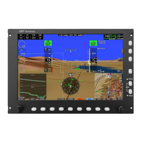
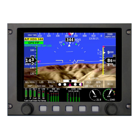
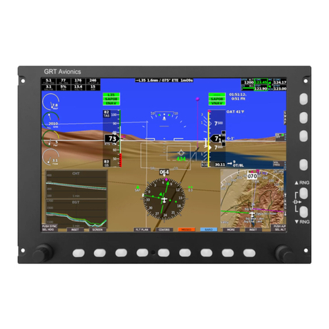
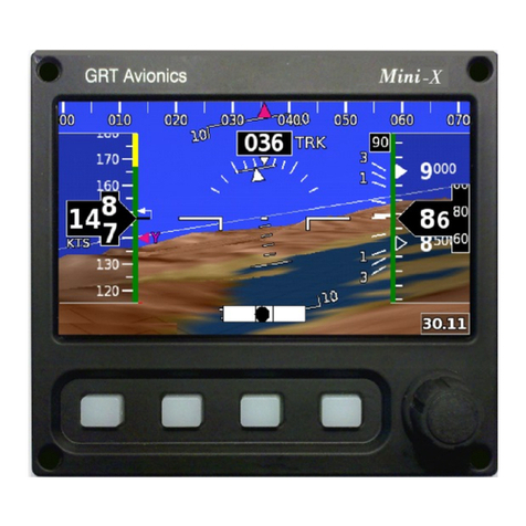
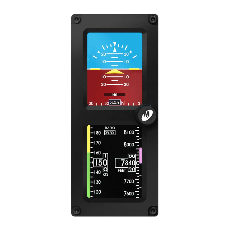
GRT Avionics Sport EX User manual

GRT Avionics, Inc. May 2019
Sport EX/Horizon EX Install. Manual I Rev. A
FOREWORD
Congratulations on your purchase of the GRT Avionics EFIS! We are pleased that you
have chosen our product to meet your flying needs!
This manual describes the installation of the GRT Sport EX and Horizon EX EFIS using
the software version shown in the Record of Revisions. Some differences may be
observed when comparing the information in this manual to other software versions.
Every effort has been made to ensure that the information in this manual is accurate and
complete. Visit the GRT website, www.grtavionics.com, for the latest manuals, software
updates and supplemental information concerning the operation of this and other GRT
products. GRT is not responsible for unintentional errors or omissions in the manual or
their consequences.
Information in the document is subject to change without notice. GRT Avionics, Inc.
reserves the right to change or improve their products and to make changes in the content
of this material without obligation to notify any person or organization of such changes or
improvements.
Copyright © 2001 - 2019 GRT Avionics, Inc. or its subsidiaries. All rights reserved.

GRT Avionics, Inc. May 2019
Sport EX/Horizon EX Install. Manual II Rev. A
RECORD OF REVISIONS
Revision
Date
Sport
SW Revision
Description
A
May 2019
All
Re-issue as a standalone manual for Sport
EX/Horizon EX.

GRT Avionics, Inc. May 2019
Sport EX/Horizon EX Install. Manual III Rev. A
Contents
FOREWORD....................................................................................................................I
RECORD OF REVISIONS..............................................................................................II
SECTION 1: GENERAL DESCRIPTION.........................................................................1
1-1: Introduction...........................................................................................................1
1-2: Certification...........................................................................................................2
1-3: System Description and Architecture....................................................................2
1-4: Integrating Third-Party Equipment........................................................................3
1-5: Display Unit Features and Limitations ..................................................................3
1-6: Supported Equipment...........................................................................................4
SECTION 2: PLANNING YOUR INSTALLATION ...........................................................6
2-1: Choosing Your Serial Port Assignments—the Key to a Good Installation! ...........6
2-2: Common Equipment Interfaces............................................................................7
2-2-1: Other GRT Avionics Display Units—the Inter-Display Unit Link.....................7
2-2-2: AHRS.............................................................................................................8
2-2-3: Autopilots.......................................................................................................8
2-2-4: Autopilot Using GRT Avionics Servos............................................................8
2-2-5: Trio Avionics and TruTrack Flight Systems External Autopilots.....................8
2-2-6: ADS-B Receivers...........................................................................................9
2-2-7: ADS-B GPS Output .......................................................................................9
2-2-8: Remote Transponders...................................................................................9
2-2-9: Panel-Mounted Transponders .....................................................................10
2-2-10: Communication and Navigation Radio Tuning...........................................10
2-2-11: External GPS Sources...............................................................................10
2-2-12: IFR GPS Navigator Sources......................................................................10
2-2-13: GPS Data to External Devices...................................................................11
2-3: Gray Code Altitude Encoder Output ...................................................................11
2-4: USB Port ............................................................................................................11
2-5: Optional Features...............................................................................................11
2-6: Analog Inputs/Audio Output................................................................................12
2-7: Basic Engine Monitoring Functions ....................................................................12
2-8: Loss of GPS Data...............................................................................................12
2-9: For More Information..........................................................................................13
SECTION 3: PHYSICAL INSTALLATION.....................................................................14

GRT Avionics, Inc. May 2019
Sport EX/Horizon EX Install. Manual IV Rev. A
3-1: Display Unit Installation ......................................................................................14
3-2: Remote Digital Magnetometer Installation..........................................................14
3-3: Cooling Considerations ......................................................................................15
3-4: Pitot-Static Connections .....................................................................................15
3-5: Angle-of-Attack Pressure Port Connection.........................................................15
SECTION 4: WIRING....................................................................................................16
4-1: General Guidelines.............................................................................................16
4-2: Power Connections ............................................................................................17
4-3: Ground Connections...........................................................................................18
4-4: Digital Magnetometer Wiring ..............................................................................18
4-5: Specific Equipment Interconnect Details ............................................................18
4-6: Warning Light Output..........................................................................................19
SECTION 5: Initial Checkout, Basic Configuration Settings and Calibration.................20
5-1: Display Unit Checkout........................................................................................20
5-2: Configuring the Serial Ports................................................................................20
5-3: Trig TT22 (RS-422 Port).....................................................................................21
5-4: Required Setup for the Internal GPS..................................................................21
5-5: Multiple AHRS Inputs .........................................................................................21
5-6: Defining Magnetometer Connections .................................................................22
5-7: AHRS/Air Data Computer Test...........................................................................22
5-8: Setting AHRS Orientation...................................................................................23
5-9: Magnetometer Location Validation.....................................................................24
5-10: Set Final Magnetometer and Instrument Orientation........................................25
5-11: Check the Uncorrected Magnetic Heading.......................................................25
5-12: Fine Magnetometer Calibration Procedure.......................................................26
5-13: Measuring the Accuracy of the Magnetic Heading ...........................................28
5-14: How Accurate Should the Magnetic Heading Be?............................................28
5-15: Basic Engine Monitoring Required Settings .....................................................29
5-16: Other Required Settings and Options...............................................................30
Appendix.......................................................................................................................32
A-1: Sport EX/Horizon EX Mounting Template..........................................................33
A-2: External Module Diagrams.................................................................................34
A-3: Digital Magnetometer Installation Diagram ........................................................35
A-4: Sport EX/Horizon EX Connector A Pinout Diagram...........................................36

GRT Avionics, Inc. May 2019
Sport EX/Horizon EX Install. Manual V Rev. A
A-5: Sport EX/Horizon EX Connector B Pinout Diagram...........................................37
A-6: Digital Magnetometer Pinout Diagram ...............................................................38
A-7: Angle-of-Attack (AOA) Installation and Calibration.............................................38
A-7-1: Sensed AOA Installation..............................................................................38
A-7-2: Calculated AOA Installation.........................................................................39
A-7-3: Calibration of the AOA (Calculated and Sensed) ........................................39
A-8: Basic Engine Monitoring Wiring .........................................................................40
A-9: Common Tachometer Connections....................................................................41
A-10: Trim/Flap Position Sensor Wiring.....................................................................42
A-11: Sport EX/Horizon EX Display Unit Specifications.............................................43
A-16: Table of Figures...............................................................................................44
A-17: List of Tables....................................................................................................45

GRT Avionics, Inc. May 2019
Sport EX/Horizon EX Install. Manual 1 Rev. A
SECTION 1: GENERAL DESCRIPTION
1-1: Introduction
This document provides the physical, mechanical and electrical characteristics and
installation requirements for the GRT Sport EX Electronic Flight Instrumentation System
(EFIS) and GRT Horizon EX Display Unit.
This manual is set up in order to match the steps you will follow to install this equipment.
•Description of the display unit –What the equipment does.
•Planning your Installation - What this equipment can do for you.
•Physical installation –How to install it.
•Wiring –How to wire it.
•Initial Checkout, Basic Configuration, and Calibration –How to set it up and
check it out.
This manual, the Sport EX Setup Guide and the Sport EX User’s Guide comprise the
entire set of Sport EX user documentation.
*NOTE: This manual refers to the EFIS, display unit and screen; although it may seem
like there are all interchangeable terms, it is important to note that they all refer to different
aspects of the Sport EX/Horizon EX system:
•EFIS: Electronic Flight Information System. This refers to the Sport EX/Horizon EX
system as a whole; it includes the display unit, peripheral devices and the
components that connect them together (such as wiring harnesses). Alternatively
referred to as “the system.”
•Display Unit: This is the centerpiece of the EFIS. It is made up of the electronic
components that connect to the peripheral devices and the physical elements that
the pilot uses to interact with the system. It takes the data from the peripheral
devices, processes it and then displays a human-readable version of that data on
its screen for the pilot to use. Abbreviated and referred to as “DU;’ may also be
referred to by model name, “Sport EX/Horizon EX.”
•Screen: This is the physical screen of the Display Unit; it’s what all the data from
the system is displayed on for the pilot’s use.

GRT Avionics, Inc. May 2019
Sport EX/Horizon EX Install. Manual 2 Rev. A
1-2: Certification
The GRT Sport EX/Horizon EX EFIS is not certified for installation in FAA Type
Certificated Aircraft. It is designed and intended for installation in VFR aircraft licensed as
Experimental or Light-Sport.
1-3: System Description and Architecture
The GRT Sport EX EFIS consists of a panel-mounted Display Unit and an optional
remotely-mounted magnetometer. The Sport EX and Horizon EX are identical
physically, with the exception that the Horizon EX does not include an internal
Attitude/Heading Reference System (AHRS), air data inputs or internal GPS.
Dimensional drawings for the Sport EX/Horizon EX display units and the magnetometer
are provided in the Appendix sections A-1: Sport EX/Horizon EX Mounting Template
and A-2: External Module Diagrams.
The display unit provides a graphical display of primary flight data, moving map/HSI and
engine data. The Horizon EX requires a connection to an external GPS in order to display
flight and navigation data. Both the Horizon EX and the Sport EX require a connection to
a GRT Engine Information System (EIS) Engine Monitor in order to display engine data.
The Sport EX may be operated as a single or multiple screen system. Within each display
unit is a processor, power supply and screen that allow it to process and display
information independent of another EFIS display unit (except for unique data that may be
coming from other display units). This allows multiple screens to provide redundancy.
Multiple screens are normally linked together via a serial inter-display link to share pilot
entries, such as baroset, dimming, flight plan, etc…
Interfacing to other systems is accomplished via serial ports, and in some cases, the USB
port. The Sport EX is also connected to the aircraft pitot-static system for sensing
airspeed, altitude and vertical speed. The internal AHRS provides roll and pitch attitude
data. When a magnetic heading is provided via the remote magnetometer, the gyro
heading data is also provided. Without the magnetic heading data from the
magnetometer, gyro-stabilized GPS ground track is provided. The GRT AHRS is unique
in the industry in that it can provide attitude data without external aiding from air data or
GPS.
An internal GPS is standard in the Sport EX. Any external GPS may also be used, as long
as its serial data output is in one of the commonly used avionic formats. Most GPS units
will continuously transmit their flight plan, allowing the EFIS to display the flight plan on
its Map and Flight Plan pages. This ability is useful for adding IFR GPS capability to the
Sport system via an IFR-approved GPS. Note that only the GPS functions will be
transmitted via a GPS serial output, such as position, ground track, groundspeed, flight
plan, etc…Other data provided to an external GPS (such as weather) are not displayed
on the GRT EFIS screen (unless this data is also provided to the EFIS, such as weather
GRT Avionics, Inc. May 2019
Sport EX/Horizon EX Install. Manual 3 Rev. A
from an ADS-B receiver). Database information (such as airport frequencies, runway
information, etc…) will always come from the EFIS navigation database.
When the GRT Avionics Engine Information System (EIS) unit is connected to the EFIS,
its data is displayed on the EFIS screen. The EFIS enhances the usefulness of the engine
data by adding such features as an EGT time history, percent power and engine efficiency
(specific fuel consumption). The EIS may include its own digital display or may be fully
remote. The ENG page on the EFIS is dedicated to engine and environmental
parameters. Engine data can also be displayed on a portion of the primary flight display
page.
1-4: Integrating Third-Party Equipment
GRT Avionics differentiates itself from other manufacturers by embracing compatibility
with third-party equipment. This allows new technologies to be adopted quickly and gives
the owner the ability to take full advantage of the advances made in a competitive
marketplace. This includes equipment like Comm/Nav radios, transponders, ADS-B
transponders/receivers and many other devices. The addition of a second or third display
unit doubles or triples the number of available serial and USB ports, allowing for the use
of more third-party devices. The inter-display link between display units also allows for
data from most devices to be shared amongst the units for redundancy and convenience.
See section 2.2 - Common Equipment Interfaces, the Appendix of this manual or the
Support section of the GRT Avionics website (www.grtavionics.com) for more information
on the various GRT system & third-party equipment configurations.
1-5: Display Unit Features and Limitations
A partial list of features and limitation includes:
•Complete Primary Flight/Map/Engine display functionality (optional sensors
required).
•Optional Synthetic Vision with 10-mile range; displays terrain, obstacles, airports
and more.
•Sunlight-readable LCD displays; dimmable to less than 5 nits for night flying.
•Internal AHRS/Air Data computer; provides critical attitude, altitude and airspeed
data (Sport EX).
•Supports internal GRT GPS, external GRT GPS Safe-Fly module and third-party
GPS.
•High-Integrity AHRS; does not require pitot-static or GPS aiding (Sport EX).

GRT Avionics, Inc. May 2019
Sport EX/Horizon EX Install. Manual 4 Rev. A
•Internal, world-wide database.
•Receives deviation data from Nav radios (excluding those with composite outputs).
•ADS-B transponder/receiver support; optional display of weather and traffic.
•Displays Traffic Information Service (TIS) traffic (when used with Mode S
transponder).
•Interfaces with Garmin SL30/40 to display VOR/ILS/GS and tune preset radio
frequencies.
•Fully-integrated autopilot functionality for GRT and third-party units.
•Flight director.
•Customizable split-screen views, PFD-MFD screen swap, Engine Page and
Moving Map overlays.
•Up to six high-speed serial ports (Three standard; an additional three serial ports
may be optionally added).
•Optional ARINC 429 expansion module; allows full integration with Garmin panel-
mounted GPS.
1-6: Supported Equipment
The list of serial-port compatible equipment includes:
•ADS-B (Traffic and Weather)
•GRT EIS Engine Monitor (All Versions)
•GRT Autopilot Servos
•External Autopilots (Trio Avionics and TruTrack Flight Systems)
•Single or Dual GPS Receivers (All Types)
•Full Nav Interface with Garmin:
oGNC Series Nav/Comm (420/420W)
oGNS Series GPS/Comm (480) and GPS/Nav/Comm
(430/430W/530/530W)
oGTN Series GPS/MFD (625/725), GPS/Comm/MFD (635) and
GPS/Nav/Comm/MFD (650/750)
•Single or Dual Interface with Garmin SL30/SL40

GRT Avionics, Inc. May 2019
Sport EX/Horizon EX Install. Manual 5 Rev. A
•XM Satellite Weather
•Guardian Avionics CO Guardian Series CO Detector
•TIS Traffic Datalink (GTX 330)
•Zaon Flight Systems PCAS XRX and MRX
•BF Goodrich WX-500 Stormscope
•Vertical Power VP-X Series Electronic Circuit Breaker System
•Serial Data Input Transponders
•TCAS (Traffic Collision Avoidance System/Traffic Alert and Collision Avoidance
System)

GRT Avionics, Inc. May 2019
Sport EX/Horizon EX Install. Manual 6 Rev. A
SECTION 2: PLANNING YOUR INSTALLATION
Modern flight instrumentation systems may seem intimidating, but they can be easier to
install than their analog counterparts. This section provides some basic information for
aircraft builders new to the world of electronic flight display systems.
2-1: Choosing Your Serial Port Assignments—the Key to a
Good Installation!
A key element to designing a glass-panel installation is the communication between
different components of the system, which occurs primarily through the serial port
connections. For systems with multiple display units, it is essential to consider the effect
of any single device failure—a power bus, GPS unit, etc… Although less likely to occur,
it is also important to consider the effects of multiple device failures on the system. These
considerations are pivotal to any airplane that’s operated in instrument conditions.
Multiple device failures are unlikely; however, they can occur in conditions that effect
multiple elements of the plane’s avionics. Such conditions include static discharge (not a
consideration in aluminum airplanes, but essential to consider with fiberglass airplanes),
water leaking into the airplane (when entering the plane during rain, any opening in the
canopy during flight, especially the vents), an over-voltage condition that can occur if the
battery becomes disconnected, loss of charging, etc…
Electrical connections to the EFIS display unit are made through the D-sub connectors
affixed to it and its accompanying wiring harnesses. Six of the terminal positions in the
connectors are reserved for use as serial ports.
All serial ports are user-configurable, allowing them to be used with a wide variety of other
equipment. Each serial port consists of two connections–a Transmit (OUT) and a
Receive(IN)–that exchange information between the display unit and aconnected device,
such as a GPS, radio or autopilot. Some devices will only transmit data (such as a GPS),
while some will only receive data (such as altitude data to a transponder). Some devices
transmit and receive data, such as autopilot servos.
A stream of serial data is like a sentence, with data packets being the words of that
sentence. Data packets are transmitted in a predetermined order and frequency. This
frequency is known as the baud rate. A device that communicates at a baud rate of 9600
delivers 9,600 coded data packets per second in a sequence that the receiving device
expects. The baud rate of a serial port in the display unit must be configured to match
that of the device connected to it. Note that when two devices share one serial port, they
mush use the same baud rate.
Some limitations that should be considered when planning your serial port
connections:

GRT Avionics, Inc. May 2019
Sport EX/Horizon EX Install. Manual 7 Rev. A
•The baud rate set for the serial port in the display unit corresponds to BOTH the
serial input and output.
•The type of function for a DU serial input does not have to match; the baud rate,
however, MUST match. For example, Serial Input 1 on the DU could be wired to
an EIS engine monitor. It is configured for 9600 baud. Serial Output 1 on the DU
could then be used to send altitude data to a transponder, if it accepted data at
9600 baud.
•The hardware design of the serial inputs to the DU can’t exceed RS-232 standard
loads; this ensures that any standard RS-232 output can provide data to multiple
EFIS display units with no loss of fidelity. For example, since serial output from an
external GPS can be wired to multiple GRT EFIS display units, its signal can be
corrupted if the loading from the EFIS exceeds the standard.
•The Sport EX serial ports are all high-speed, meaning that any serial port can be
used with any device, regardless of the baud rate the connection may require.
2-2: Common Equipment Interfaces
This section is an overview of the typical interconnections that are made to other avionics.
It is intended to inform you of the benefits of connecting your GRT EFIS to other
equipment. Refer to the latest revisions of the Equipment Supplements for each third-
party component for the most detailed and up-to-date wiring and setup information
(www.grtavionics.com/home/compatible-equipment/).
2-2-1: Other GRT Avionics Display Units—the Inter-Display Unit Link
This connection allows two or more display units to function as one integrated system, so
pilot inputs do not need to be duplicated on each display unit. The following pilot entries
are always shared over the inter-display unit link:
•Baroset
•Display Dimming Level
•Flight Plan
•Limits (compared between display units at power-up)
•Autopilot/Flight Director Mode and Targets
•EFIS Navigation Mode
The inter-display unit link can also share specified data that only a single display unit may
be receiving, including any analog inputs.

GRT Avionics, Inc. May 2019
Sport EX/Horizon EX Install. Manual 8 Rev. A
2-2-2: AHRS
The Sport EX/Horizon EX can receive two sets of AHRS data. Typically, one set of AHRS
data comes from the DU’s internal AHRS while the second comes from a serial port
connection to an external AHRS. This only applies to the Sport EX, with the Horizon EX
requiring both sets of data to come from external AHRS sources. The external AHRS
connection may come from a standalone AHRS unit or from the internal AHRS of a
separate Sport EX display unit. Providing the EFIS with multiple attitude sources allows
for automatic cross-checking of the attitude data. An “AHRS Miscompare” warning will
occur if the roll and pitch attitude differ more that the test threshold. Either set of AHRS
data can be chosen by the pilot to drive the EFIS. The EFIS will default to “BOTH,”a
composite of the two AHRS data sets.
2-2-3: Autopilots
An autopilot provides the greatest benefit for the cost of almost any addition to the
airplane. It is an essential tool for single pilot IFR and highly beneficial for any VFR pilot
that undertakes cross-country flights. The autopilot frees up the pilot to perform other vital
tasks, such as looking for traffic, radio tuning, evaluating imminent weather, etc…We
highly recommend it for all airplanes, with the exception of those that are not flown cross-
country. If you have chosen not to install an autopilot, but may do so in the future, we
recommend installing the servo wiring at the very least, and possibly installing the servo
mounting kits as well. This will make the addition of the servo easier in the future. This
also increases the value of the airplane for any future owner if it is sold without an autopilot
installed.
2-2-4: Autopilot Using GRT Avionics Servos
An autopilot using GRT Servos provides excellent performance and is the easiest
configuration to implement. The installation will require wiring for the servos, mounting
kits to attach the servos to your airplane, a power-switch for the servos and an
engage/disengage button. A single serial port is used to control both the roll and pitch
servos.
When using multiple GRT EFIS display units, any display unit can function as the Autopilot
Mode Controller. Adding an autopilot switch to a second display unit ensures functionality
in the event that the primary autopilot-controlling display unit fails.
2-2-5: Trio Avionics and TruTrack Flight Systems External Autopilots
Most of our customers use GRT Servos for their autopilot needs. However, airplanes with
existing autopilots can still interface with any GRT EFIS. This is accomplished via a serial
output from the EFIS for lateral-only steering. Autopilots that provide vertical steering
require an ARINC 429 adapter to receive GPSS and GPSV commands, which requires
the use of both a serial input and an output from the EFIS.

GRT Avionics, Inc. May 2019
Sport EX/Horizon EX Install. Manual 9 Rev. A
External autopilots that include their own source of gyro data provide some degree of
redundancy with the AHRS data from the EFIS when the autopilot is coupled. This benefit
is offset by slight transients in pitch when the autopilot is initially coupled to the EFIS. It
also requires more button presses than when GRT servos are used. Since GRT servos
can be mounted in place of TruTrak or Dynon servos, many of our customers choose to
sell their autopilot and install GRT servos; in this instance, the existing mounting kits and
wiring can be used. The required changes to the electrical connections for this switchover
are not difficult to make.
2-2-6: ADS-B Receivers
All ADS-B receivers that provide data in the standard ADS-B format can be wired to the
display unit for weather and traffic data. Most ADS-B receivers provide data in this
standard format, except for some Garmin units. We find the inclusion of ADS-B weather
and traffic to be very beneficial and highly recommend its integration into your airplane’s
avionics systems. ADS-B receivers can be purchased for as little as a few hundred
dollars.
2-2-7: ADS-B GPS Output
The GPS output from the Sport EX’s internal GPS is NOT FAA 2020 compliant for use
with ADS-B or mode S with extended squitter transponders. If this GPS position data is
used, the FAA will detect that a noncompliant GPS is being used. However, the GRT
Safe-Fly GPS is 2020 ADS-B compliant and is approved by the FAA for this use. This
GPS also includes a serial combiner that provides the EFIS with 3 more serial ports (input
and output). Additionally, this GPS provides accuracy and integrity data that is used by
the Sport EX. The integrity validation performed by this GPS is similar to that performed
by IFR-certified GPS navigators.
2-2-8: Remote Transponders
The Sport EX supports fully remote transponders, including the Trig TT22 and uAvionix
ESX.
These have several advantages over traditional panel-mounted transponders:
•No panel space is required.
•The EFIS interface is easy to use.
•More flexibility in the mounting location.
•The EFIS can have automated control over the transponder.
•Multiple display units provide multiple ways to control the transponder.

GRT Avionics, Inc. May 2019
Sport EX/Horizon EX Install. Manual 10 Rev. A
A serial input and output are required to interface a display unit with a uAvionix remote
transponder. If the Trig TT22 is being used, an RS-422 interface (or a serial input and
output with a Trig Adapter) is needed to connect it to the display unit. When the remote
transponder and display unit are interfaced, the connection provides altitude data and
control of the transponder to the display unit.
2-2-9: Panel-Mounted Transponders
The EFIS provides altitude encoding information to all common transponders. Gray code
outputs are provided for older transponders that do not have a serial input for altitude
data. The Sport EX requires an external adapter for Gray code altitude encoding outputs.
Newer transponders may allow either serial output or Grey code.
2-2-10: Communication and Navigation Radio Tuning
The EFIS has the ability to load the Garmin SL30 and SL40 radios with frequency pre-
sets, allowing convenient selection of these frequencies from the front panel controls of
the radio. For the SL30, the EFIS can also tune the navigation radio. This data is
transmitted to the radio via an RS-232 serial output from the EFIS display unit.
Display of Navigation Data from the SL30: The EFIS provides an HIS and other functions
that display and use the VOR bearing data provided by the SL30 Nav/Com. Localizer and
glide slope deviation data is also displayed on the DU from this radio. This data is
transmitted to the radio via an RS-232 output from the EFIS display unit.
Multi-Display Unit Considerations: Although the navigation data from the SL30 is
communicated to other display units via the inter-display unit link, it is preferable to
connect the serial data output from the SL30 to two display units independently. This
allows the SL30 navigation data to be displayed in the event that one of the display units
fails. One serial data output from the SL30 may be connected to multiple display units.
Only one serial data output TO the SL30/SL40 is provided, but in this case, redundancy
is not an issue. If the display unit that provides the tuning data to the SL30/SL40 is non-
operational, the radio would simply be tuned with its front panel controls.
2-2-11: External GPS Sources
Practically all external GPS receivers provide a serial output that is compatible with the
input formats accepted by the EFIS display unit. Position, groundspeed, ground track and
the flight plan are normally provided by the GPS. The display unit supports two GPS
inputs. The GPS source used by the EFIS is selected on the display unit Navigation Mode
softkey.
2-2-12: IFR GPS Navigator Sources
The Sport EX is fully-compatible with IFR GPS navigators from Garmin and Avidyne. The
optional ARINC 429 Interface is required to receive VOR/ILS information from these

GRT Avionics, Inc. May 2019
Sport EX/Horizon EX Install. Manual 11 Rev. A
devices, as well as to provide them with EFIS data that the GPS can use for enhanced
functionality. A serial connection is enough to receive the GPS position, groundspeed,
ground track and flight plan data.
2-2-13: GPS Data to External Devices
Configuring any serial output to “Autopilot-NMEA 0183” will provide NMEA0183 GPS
position, speed and ground track data; the flight plan is not transmitted.
2-3: Gray Code Altitude Encoder Output
Older transponders use an interface called Gray Code to receive data from altitude
encoders. Since the Sport EX does not contain an internal altitude encoder, an external
adapter is used for interfacing with this type of transponder. All newer transponders have
the option to use serial data instead of Gray Code, so this adapter is not commonly used.
2-4: USB Port
In some cases, other equipment may communicate with the display unit via a USB
connection. A USB port is easy to connect and transmits large amounts of data quickly.
USB devices do not require you to program a baud rate. The Sport EX and Horizon EX
both have a single USB port that may be used for one USB device. Alternatively, you may
attach a USB hub to connect up to three devices. Software updates are also delivered to
the DU via USB—simply install the software update files onto a USB thumb drive from
the GRT website, then connect the thumb drive to the display unit’s USB port. The DU
will upload the files as per the Update instructions found in the Sport EX Setup Guide.
2-5: Optional Features
There are several optional features that can be bundled with your Sport EX/Horizon EX,
allowing you to purchase the EFIS at a lower total-cost and to expand the capabilities of
your EFIS. These expanded features can be implemented during the initial build phase
or at a later date, usually without having to remove the display unit from your instrument
panel. The optional features can also be added after your initial purchase, either in a
group at a discounted rate or individually as they are needed. The features are:
•Moving Map: Includes free database updates for US territory. Worldwide
database coverage is provided a Jeppesen Database Subscription.
•Synthetic Vision/Terrain Relief Map: 10-mile range; high-resolution, forward-
looking synthetic vision includes terrain, runways, obstacles, waypoints and traffic.
•ADS-B Displays for Traffic and Weather on the PFD and MAP Screens:
Requires a connection to any ADS-B receiver that provides data in the standard
GDL-90 format.

GRT Avionics, Inc. May 2019
Sport EX/Horizon EX Install. Manual 12 Rev. A
•Bluetooth wireless interface to the free GRT Connect Android App.
•3 Additional Serial Ports (3 are Standard)
•Analog Inputs/Audio Output (See Section 2.X: Analog Inputs/Audio Output).
•Basic Engine Monitoring (See Section 2.X: Basic Engine Monitoring
Functions)
•Angle-of-Attack Sensing*
•Touchscreen*
*NOTE: These optional features require a hardware upgrade and need to be sent in to
GRT in order to add them.
2-6: Analog Inputs/Audio Output
The Sport EX/Horizon EX includes four analog inputs and an audio output as an option.
The analog inputs allow the EFIS to measure up to four individual voltages in the airplane.
Typically, these inputs are used to display the trim and flap positions, but they can be
user-defined for just about any purpose. For example, the inputs may be defined and
used to display fuel levels, fuel pressure, water temperature or even ignition advance (if
compatible with your ignition system).
The audio output provides a method of alerting the pilot when limits are exceeded, gives
altitude call-outs on approach, traffic alerts and much more. The audio output is wired
through the intercom or audio panel.
2-7: Basic Engine Monitoring Functions
Basic engine monitoring provides oil temperature, oil pressure, tachometer, hourmeter
and flight timer. The option is provided with the required sensors. These sensors are
compatible with the GRT Engine Information System (EIS), allowing for a simple
integration of the system in the future. Other engine monitoring can be added using the
optional analog inputs. Note that EGT and CHT monitoring cannot be performed via the
analog inputs due to the very small voltages generated by the EGT/CHT probes.
2-8: Loss of GPS Data
While it is expected that the EFIS will be provided with GPS data for accurate navigation
information, it is a possibility that all GPS data could be lost. If this occurs while in flight,
the EFIS will dead-reckon from its last known GPS position. Due to varying winds and
sensor errors, the EFIS system position will degrade in accuracy over time. The intent of

GRT Avionics, Inc. May 2019
Sport EX/Horizon EX Install. Manual 13 Rev. A
the dead-reckoned system position is to provide approximate position information so that
the pilot has time to implement other means of navigation, such as visual observations,
VOR, etc…
2-9: For More Information
Depending on what your “mission” is, you may want a simple VFR system, or an IFR
system with many built-in redundancies. The GRT system enables customization for the
entire range of possible configurations, from simple to sophisticated, depending on the
builder’s desire and skill level.
While this manual covers the very basics of EFIS wiring and communication, along
with GRT Sport-specific details, there are many very important safety aspects of
aircraft wiring that we cannot even begin to discuss in this manual. The techs at
GRT recommend the following sources for more information on proper aircraft
avionics & electrical system design:
•The “Aeroelectric Connection” by Bob Nuckolls is a great place to start. It covers
everything from the very basics of electricity to the proper design and installation
of sophisticated IFR-capable systems.
•EAA columnist Tony Bingelis’s books have long been a staple of experimental
aircraft builder knowledge. In addition to wiring considerations, Mr. Bingelis
discusses all aspects of kitplane building, from spinner to tail. The books are: The
Sportplane Builder: Aircraft Construction Methods, Sportplane Construction
Techniques: A Builder’s Handbook, Firewall Forward: Engine Installation Methods
and Tony Bingelis on Engines.
•FAA Advisory Circular 43.13-2B provides the “certified” reference for safe and
durable aircraft wiring techniques, though it is a bit outdated. It is available online
as a free download from www.faa.gov.
•The Experimental Aircraft Association has compiled a collection of videos called
“Hints for Homebuilders”on its website, www.eaa.org. A quick search through
these will give you valuable hints on various wiring topics, including properly
crimping D-sub/Molex connector pins.

GRT Avionics, Inc. May 2019
Sport EX/Horizon EX Install. Manual 14 Rev. A
SECTION 3: PHYSICAL INSTALLATION
3-1: Display Unit Installation
Mount the display unit(s) in the desired location in the instrument panel. The main
consideration in choosing a location is the ability to view the display unit and reach its
controls. Since the screen is fully sunlight-readable, no consideration for shielding the
display unit from sunlight is required. Be mindful of the space behind the instrument panel
as well; some aircraft, such as those with tip-up canopies, for example, have canopy
supports that may interfere with the back of the DU when the canopy is closed. See the
Appendix section A-1: Sport EX/Horizon EX Mounting Template for display unit
dimensions and clearance requirements for the rear of the unit.
1. For panel-mount style display units, the use of nut plates behind the instrument
panel greatly simplify the task of installing and removing the four screws used to
retain the display unit in the panel. #6 socket cap stainless steel screws are
recommended.
2. For radio rack style display units, the #6 screws on the side of the unit (two per
side) should be used to attach the display unit to the radio rack.
3-2: Remote Digital Magnetometer Installation
The remote magnetometer must be placed in an area of the airplane with little or no
electromagnetic interference. The cable is 20’long and designed to reach out to the
wingtip or tail. The magnetometer is marked with an arrow pointing in the direction of
flight. Mount it with the arrow pointing forward, parallel to the centerline of the airplane.
There is not a designated “top” of the magnetometer, so it can be turned on its side for
easier mounting. The side of a wing tip rib is a simple place to put it. The arrow on the
magnetometer should be parallel with the centerline of the airplane for yaw. Pitch attitude
is not critical as long as it is within 60° nose up or nose down.
60° up limit
Longitudinal Axis
60° down limit
Figure 3-1: Magnetometer Pitch Range
*NOTE: The most common cause of magnetic sensing error is simply magnetic
disturbances near the magnetometer. This can be caused by ferrous metal (any metal
This manual suits for next models
1
Table of contents
Other GRT Avionics Avionic Display manuals
Popular Avionic Display manuals by other brands

uAvionix
uAvionix AV-30-E pilot's guide

Dynon
Dynon SkyView Classic Pilot's user guide

Dynon Avionics
Dynon Avionics EFIS-D10 installation guide

NORMARC
NORMARC NM 7000 Series Installation & Commissioning Handbook

Aircatglobal
Aircatglobal VirtualFly SOLO AIRLINER-RS user manual

Garmin
Garmin CIRRUS PERSPECTIVE SR2x pilot's guide

Dynon
Dynon SkyView Classic Pilot's user guide

Garmin
Garmin Cessna Caravan G1000 Cockpit reference guide

Kelly Manufacturing
Kelly Manufacturing RCA 2610-2 P Installation & operation guide

Honeywell
Honeywell EGPWS MK V pilot's guide

Avidyne
Avidyne IFD440 pilot's guide

Garmin
Garmin Cessna Caravan G1000 pilot's guide