Grunbeck GENO-WT 42 User manual

We understand water.
Accessories | Heat exchanger GENO-WT
42/76/105
Operation manual

General Contact
Germany
International Sales
Phone +49 9074 41-145
Service
Phone 09074 41-333
Availability
Monday to Thursday
7:00 am - 6:00 pm
Friday
7:00 am - 4:00 pm
We reserve the right to technical modifications.
© by Grünbeck Wasseraufbereitung GmbH
Original operation manual
Edition: June 2021
Order no.: 100107170000_en_005

Table of contents
3 | 56
Table of contents
1Introduction ..................................... 4
1.1 Validity of the manual ...................... 4
1.2 Other applicable documents ............ 4
1.3 Product identification ....................... 5
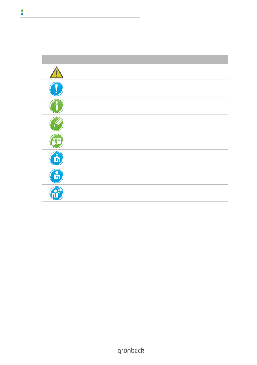
1.4 Symbols used .................................. 6
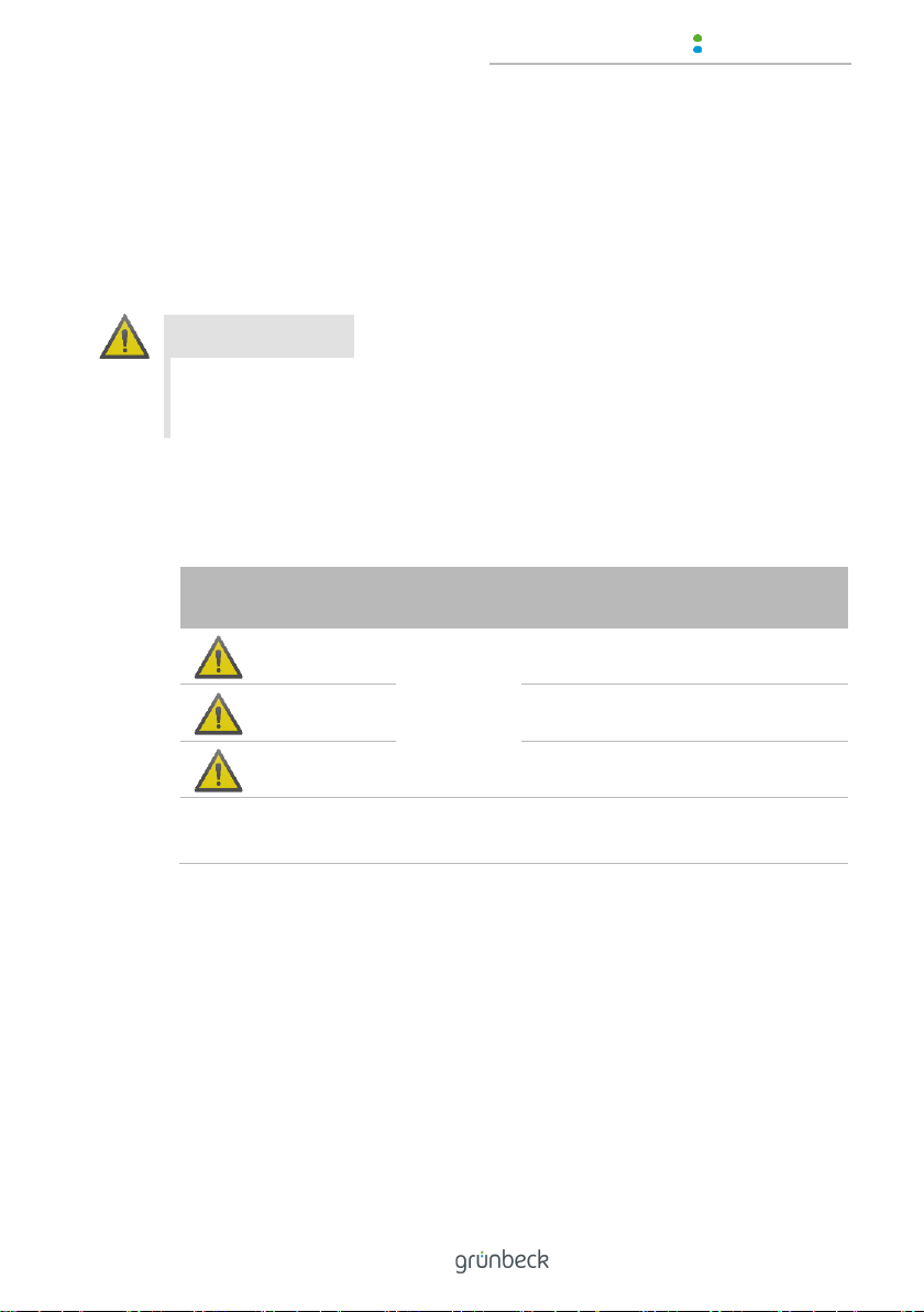
1.5 Depiction of warnings ...................... 7
1.6 Demands on personnel.................... 8
2Safety ............................................. 10
2.1 Safety measures............................ 10
2.2 Product-specific safety
instructions..................................... 12
2.3 Conduct in emergencies ................ 13
3Product description ...................... 14
3.1 Intended use.................................. 14
3.2 Product components...................... 15
3.3 Accessories ................................... 16
4Transport and storage.................. 17
4.1 Shipping/Delivery/Packaging ......... 17
4.2 Transport ....................................... 17
4.3 Storage .......................................... 17
5Installation ..................................... 18
5.1 Requirements for the installation
site ................................................. 22
5.2 Checking the scope of supply........ 23
5.3 Installing the heat exchanger......... 24
6Start-up/Commissioning .............. 29
6.1 Venting the system/checking for
leaks .............................................. 30
6.2 Checking the system for function .. 31
6.3 Handing over the product to the
owner/operating company ............. 31
7Operation/handling....................... 32
8Maintenance and repair................ 33
8.1 Cleaning ........................................ 34
8.2 Intervals ......................................... 34
8.3 Inspection ...................................... 35
8.4 Maintenance .................................. 36
8.5 Spare parts .................................... 39
8.6 Wearing parts ................................ 39
9Troubleshooting............................ 40
9.1 Observations ................................. 40
10 Decommissioning......................... 41
10.1 Temporary shutdown..................... 41
10.2 Restart ........................................... 41
11 Dismantling and disposal ............ 42
11.1 Dismantling.................................... 42
11.2 Disposal......................................... 43
12 Technical specifications .............. 44
12.1 Capacity curves of GENO-WT....... 46
13 Operation log................................. 48
13.1 Start-up/Commissioning log........... 48

Introduction
4 | 56
BA_100107170000_en_005_GENO-WT 42_76_105.docx
1 Introduction
This manual is intended for owners/operating companies, opera-
tors/users as well as qualified specialists and ensures the safe and
efficient handling of the product. The manual is an integral part of
the product.
►Carefully read this manual and the included manuals on the
components before you operate your product.
►Obey all safety and handling instructions.
►Keep this manual and all other applicable documents, so that
they are available when needed.
Illustrations in this manual are for basic understanding and can differ
from the actual design.
1.1 Validity of the manual
●Heat exchanger GENO-WT 42
●Heat exchanger GENO-WT 76
●Heat exchanger GENO-WT 105
●Special designs that essentially correspond to the standard
products given above.
1.2 Other applicable documents
●Manuals of components from other manufacturers

Introduction
5 | 56
BA_100107170000_en_005_GENO-WT 42_76_105.docx
1.3 Product identification
You can identify your product based on the product designation and
the order no. indicated on the type plate.
►Check whether the products indicated in chapter 1.1 corre-
spond to your product.
The type plate is located on the housing.
Designation
1
CE mark
2
EAC test mark
3
Obey the operation manual
4
Product designation
5
Order no.
6
Serial no.
7
Date of manufacture
8
Heating connection
9
Heating flow rate
Designation
10
Heating pressure
11
Heating supply temperature
12
Heat transfer capacity
13
Ambient temperature
14
Water temperature
15
Swimming pool pressure
16
Swimming pool flow rate
17
Nominal connection diameter
on heat exchanger

Introduction
6 | 56
BA_100107170000_en_005_GENO-WT 42_76_105.docx
1.4 Symbols used
Symbol
Meaning
Danger and risk
Important information or requirement
Useful information or tip
Written documentation required
Reference to further documents
Work that must be carried out by qualified specialists only
Work that must be carried out by qualified electricians only
Work that must be carried out by technical service personnel only

Introduction
7 | 56
BA_100107170000_en_005_GENO-WT 42_76_105.docx
1.5 Depiction of warnings
This manual contains information and instructions that you must
obey for your personal safety. The information and instructions are
highlighted by a warning symbol and are structured as shown below:
1.1.1.1
1.1.1.2 SIGNAL WORD
1.1.1.3 Type and source of hazard
1.1.1.4
●Possible consequences
►Preventive measures
The following signal words are defined subject to the degree of dan-
ger and might be used in the present document:
Warning symbol and
signal word
Consequences if the information/
instructions are ignored
DANGER
Personal
injury
Death or serious injuries
WARNING
Possible death or serious injuries
CAUTION
Possible moderate or minor injuries
NOTE
Damage to
property
Possible damage to components, the
product and/or its functions, or an ob-
ject in its vicinity

Introduction
8 | 56
BA_100107170000_en_005_GENO-WT 42_76_105.docx
1.6 Demands on personnel
During the individual life cycle phases of the product, different peo-
ple carry out work on the product. This work requires different quali-
fications.
1.6.1 Qualification of personnel
Personnel
Requirements
Operator/user
•No special expertise required
•Knowledge of the tasks assigned
•Knowledge of possible dangers in case of incorrect
behaviour
•Knowledge of the required protective equipment and
protective measures
•Knowledge of residual risks
Owner/operating com-
pany
•Product-specific expertise
•Knowledge of statutory regulations on work safety
and accident prevention
Qualified specialist
•Electrical engineering
•Sanitary engineering
(HVAC and plumbing)
•Transport
•Professional training
•Knowledge of relevant standards and regulations
•Knowledge of detection and prevention of potential
hazards
•Knowledge of statutory regulations on accident pre-
vention
Technical service
(Grünbeck's technical
service/authorised ser-
vice company)
•Extended product-specific expertise
•Trained by Grünbeck

Introduction
9 | 56
BA_100107170000_en_005_GENO-WT 42_76_105.docx
1.6.2 Authorisations of personnel
The table below describes which tasks may be carried out by whom.
Operator/
user
Owner/
operating
company
Qualified
specialist
Techni-
cal
service
Transport and storage
X
X
Installation and mounting
X
X
Start-up/Commissioning
X
X
Operation and handling
X
X
X
X
Cleaning
X
X
X
X
Inspection
X
X
X
X
Maintenance
semi-annually
X
X
annually
X
X
Troubleshooting
X
X
X
Repair
X
X
Decommissioning and restart/
recommissioning
X
X
Dismantling and disposal
X
X
1.6.3 Personal protective equipment
►As an owner/operating company, make sure that the re-
quired personal protective equipment is available.
The components below fall under the heading of personal protective
equipment (PPE):
Protective gloves
Protective footwear
Protective overall
Protective goggles

Safety
10 | 56
BA_100107170000_en_005_GENO-WT 42_76_105.docx
2 Safety
2.1 Safety measures
●Only operate your product if all components are installed
properly.
●Obey the local regulations on drinking water protection, acci-
dent prevention and occupational safety.
●Do not make any changes, alterations, extensions or program
changes on your product.
●Only use genuine spare parts for maintenance or repair.
●Keep the premises locked against unauthorised access to
protect imperilled or untrained persons from residual risks.
●Comply with the maintenance intervals (refer to chapter 8.2).
2.1.1 Mechanical hazards
●You must never remove, bridge, or otherwise tamper with
safety equipment.
●For all work on the system that cannot be carried out from the
ground, use stable, safe and self-standing access aids (e.g.
stepladders).
●Make sure that the system is set up in a way that it cannot tip
over and that the stability of the system is guaranteed at all
times.

Safety
11 | 56
BA_100107170000_en_005_GENO-WT 42_76_105.docx
2.1.2 Pressure-related hazards
●Components can be under pressure. There is a risk of injuries
and damage to property due to escaping water and unex-
pected movement of components. Check the system’s pres-
sure lines at regular intervals.
●Before starting repair and maintenance work, make sure that
all affected components are depressurised.
2.1.3 Groups of persons requiring protection
●This product is not designed to be used by persons (including
children) with reduced capabilities, lack of experience or lack
of knowledge.
●Children must be supervised to make sure that they do not
play with the product.

Safety
12 | 56
BA_100107170000_en_005_GENO-WT 42_76_105.docx
2.2 Product-specific safety instructions
CAUTION
Thermal hazard due to contact with hot surfaces
(up to 90°C)
●Burns
►Do not touch the hot surfaces of the heat exchanger and of
the components on the heating side.
►Sufficiently insulate the components on the heating side.
►Allow the components to cool down before carrying out any
work.
►Use suitable protective gloves when working on the system.
Labels on the product
Hot surface
The affixed information and pictograms must be clearly legible.
They must not be removed, soiled or painted over.
►Obey all warnings and safety instructions.
►Immediately replace illegible or damaged symbols and picto-
grams.

Safety
13 | 56
BA_100107170000_en_005_GENO-WT 42_76_105.docx
2.3 Conduct in emergencies
2.3.1 In case of leaking pool or heating water
1. De-energise the system.
2. Locate the leak.
CAUTION
Hot heating water (up to 90 °C)
●Scalding
►Wear personal protective equipment.
3. Eliminate the cause of the leaking pool or heating water.
4. Contact a qualified specialist or the technical service person-
nel, if necessary.

Product description
14 | 56
BA_100107170000_en_005_GENO-WT 42_76_105.docx
3 Product description
3.1 Intended use
●The heat exchanger GENO-WT is used for heating up pool
water (freshwater) in private or public swimming pools and
whirlpools.
3.1.1 Application limits
The heat exchanger GENO-WT is designed for counterflow opera-
tion in a dual-circuit system.
For its use, the following parameters apply as limit values for the ap-
proved substances contained in the water:
Parameters
Value
pH value
-
6.8 –7.8
Free chlorine
mg/l
< 1.3 (briefly < 20)
Chloride content
mg/l
< 500
Bromine
mg/l
≤ 6
Total hardness
°dH
< 14
On the heating side, only heating water according to VDI 2035 or
water-glycol mixes with a maximum content of 50 % glycol may be
pumped.
3.1.2 Foreseeable misuse
●Use in salt, sea or brine water is not permitted.

Product description
15 | 56
BA_100107170000_en_005_GENO-WT 42_76_105.docx
3.2 Product components
Designation
Function
1
Hose connection
for pool water
2
Bolt clamps
to fix the hose connections
3
Connections for supply
and return
for connection to the heating circuit
4
Clamps
to fix the heat exchanger
5
Clamp holder
for wall or floor mounting
6
Heat exchanger incl.
thermowell
for heat transfer and to house the temperature
sensor
7
Fastening material
4x hexagon head screw, washer, dowel

Product description
16 | 56
BA_100107170000_en_005_GENO-WT 42_76_105.docx
3.3 Accessories
Your product can be retrofitted with accessories. Please contact
your local Grünbeck representative or Grünbeck’s headquarters in
Hoechstaedt/Germany for details.
Illustration
Product
Order no.
Heat exchanger shut-off kit 1"
208 444
To hydraulically shut off a heating circulation provided
by the client on site as well as to protect the on-site
piping.
Control unit BWH-W I17/1
208 607
Is used for semi-automatic operation of the filter sys-
tem by means of a timer and to control the tempera-
ture.
Digital temperature controller
208 693
Is required if the pool water controller does not feature
a temperature control function.
Thermostat 10 –60 °C including
stainless steel thermowell
208 625
For use as maximum temperature limiter.
Product to monitor the maximum pool water tempera-
ture and to protect the piping provided by the client on
site.

Transport and storage
17 | 56
BA_100107170000_en_005_GENO-WT 42_76_105.docx
4 Transport and storage
4.1 Shipping/Delivery/Packaging
The product is packed in a cardboard box at the factory.
►Upon receipt, immediately check for completeness and
transport damage.
4.2 Transport
►Transport the product in its original packaging only.
4.3 Storage
►Protect the product from the impacts below when storing it:
•Dampness, moisture
•Environmental impacts such as wind, rain, snow, etc.
•Frost, direct sunlight, severe heat exposure
•Chemicals, dyes, solvents and their vapours

Installation
18 | 56
BA_100107170000_en_005_GENO-WT 42_76_105.docx
5 Installation
The installation of the system must be carried out by a qualified
specialist only.
NOTE
Leaks or system damage due to corrosion.
●Leaks, water loss, water damage, system failure.
►Position the dosing system for chemicals or the dosing
points//injection points in the pipe downstream of the heat
exchanger.

Installation
19 | 56
BA_100107170000_en_005_GENO-WT 42_76_105.docx
Installation example in full flow
(horizontal installation on the floor)
Designation
Below water level
Designation
Above water level
(with pipe loops)
Designation
1
Main pipe of pool water circuit
Designation
2
Heating circuit

Installation
20 | 56
BA_100107170000_en_005_GENO-WT 42_76_105.docx
Installation example in full flow (vertical installation on the wall)
Designation
Below water level
Designation
Above water level
(with pipe loops)
Designation
1
Main pipe of pool water circuit
Designation
2
Heating circuit
This manual suits for next models
2
Table of contents
Other Grunbeck Industrial Equipment manuals