English (GB)
8
4. General information
These installation and operating instructions contain all
information important for users of the Conex®DIA-2:
• technical data
• instructions on commissioning, use and
maintenance
• safety information.
Should you require further information or should you
encounter problems that are not handled in sufficient
depth in this manual, please contact Grundfos. We
shall be pleased to support you with our
comprehensive know-how in the fields of measuring
and control technology as well as water treatment.
We always welcome suggestions on how to optimise
our installation and operating instructions to satisfy
our customers.
5. Applications
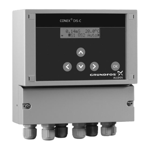
The Conex®DIA-2 instrument amplifier and
controller is suitable for measuring chlorine (Cl2),
chlorine dioxide (ClO2), ozone (O3), hydrogen
peroxide (H2O2) and pH and for controlling these
variables using appropriate actuators within the
applications described in this manual.
6. Safety
6.1 Obligations of the owner/operations
manager
The owner/operations manager must ensure that
persons working with the Conex®DIA-2 instrument
amplifier and controller fulfil these requirements:
• They are acquainted with the regulations
concerning working safety and accident
prevention.
• They have been trained in use of the device.
• They have read and understood the warning
information and handling symbols.
The owner/operations manager is also responsible
for ensuring that this manual is kept in the immediate
vicinity of the device and is always available for the
operating personnel.
6.2 Avoidance of danger
Warning
Other applications are not approved and
not permitted. Grundfos cannot be held
liable for any damage resulting from
incorrect use.
Warning
Installation and connection of the device
and the associated supplementary
components must only be carried out by
authorised personnel!
The local safety regulations must be
observed!
Warning
Switch off the power supply before
connecting the power supply cable and
relay contacts!
Do not dismantle the device!
Maintenance and repair must only be
carried out by authorised personnel!
The mounting location must be selected so
that the housing is not subjected to
mechanical loading.
Check that all settings are correct before
starting up the device!
