GS Energy GS-hybrid-3K User manual

Application
On-grid mode (daytime) On-grid mode (night)
1. PV power generation
2. Supply to load
3. Charge battery
4. Sell to grid
1. Battery supply to load
2. Grid supply to load
1. PV power generation
2. Battery supply to load
1. PV power generation
2. Charge battery
3. Grid supply to load
Off-grid mode UPS mode
For residential hybrid system
Safety System
Diversity
Flexible
Installation
Cost-effective Multi-function Plug & PlayUPS Function
1
2
1
2
3
1
24
31
2
AC current
DC current

TECHNICAL PARAMETERS
Parameters
Model
Max. input voltage (V)
MPPT voltage range (V)
Nominal input voltage (V)
GS-Hybrid-3K
550
120 ~ 550
GS-Hybrid-5K
120 ~ 550
Max. input power (W) 3800 6600
360
PV
Battery
AC output
Efficiency
General data
Standard
Voltage range (V) 40 ~ 60
Max. output power (W) 2500
Max. charge / discharge current (A) 50
Communication CAN / RS485
Nominal output power (W) 3000 5000
Voltage range (V) 180 ~ 270
Nominal output frequency (Hz) 50 / 60
Grid type Single-phase
Nominal grid current (A) 16 23
18 20
THD < 3%
MPPT efficiency
Max.efficiency
Max. battery efficiency
> 99.9%
> 97.5%
94%
366*476*173Dimensions (W*H*D) (mm)
Weight (kg)
Environmental protection rating IP65
Communication Wifi / RS485 / CAN
Ambient temperature (℃) -25 ~ 60 (> 45 derating)
Mounting Wall bracket
Noise (dB) < 30
Relative humidity 0 ~ 95%
Standard warranty 5 years
Operating altitude (m) 4000 (> 2000 derating)
Cooling Nature cooling
Display LED
EMC
Safety IEC62109, IEC62040
Topology Transformerless
EN61000-6-3, EN1000-6-1, EN61000-3-2/11, EN61000-3-3/12
Grid AS4777.2, VDE-AR-N 4105, VDE0126, G99
Address:
Tashan Industry Zone, Meilin, Ninghai, Ningbo, China
Note:
Email:

08
GS ENERGY STORAGE INVERTER USER MANUAL

08
USER MANUAL....................................................................................................................................................3
1、introduction:..........................................................................................................................................3
2、Important Safety Warning........................................................................................................................3
2.1 Symbols.................................................................................................................................................4
2.2 Safety....................................................................................................................................................4
3 lnstallation................................................................................................................................................6
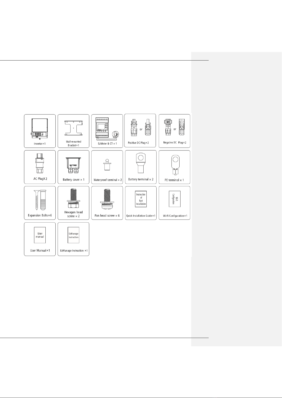
3.1 Packing List ........................................................................................................................................6
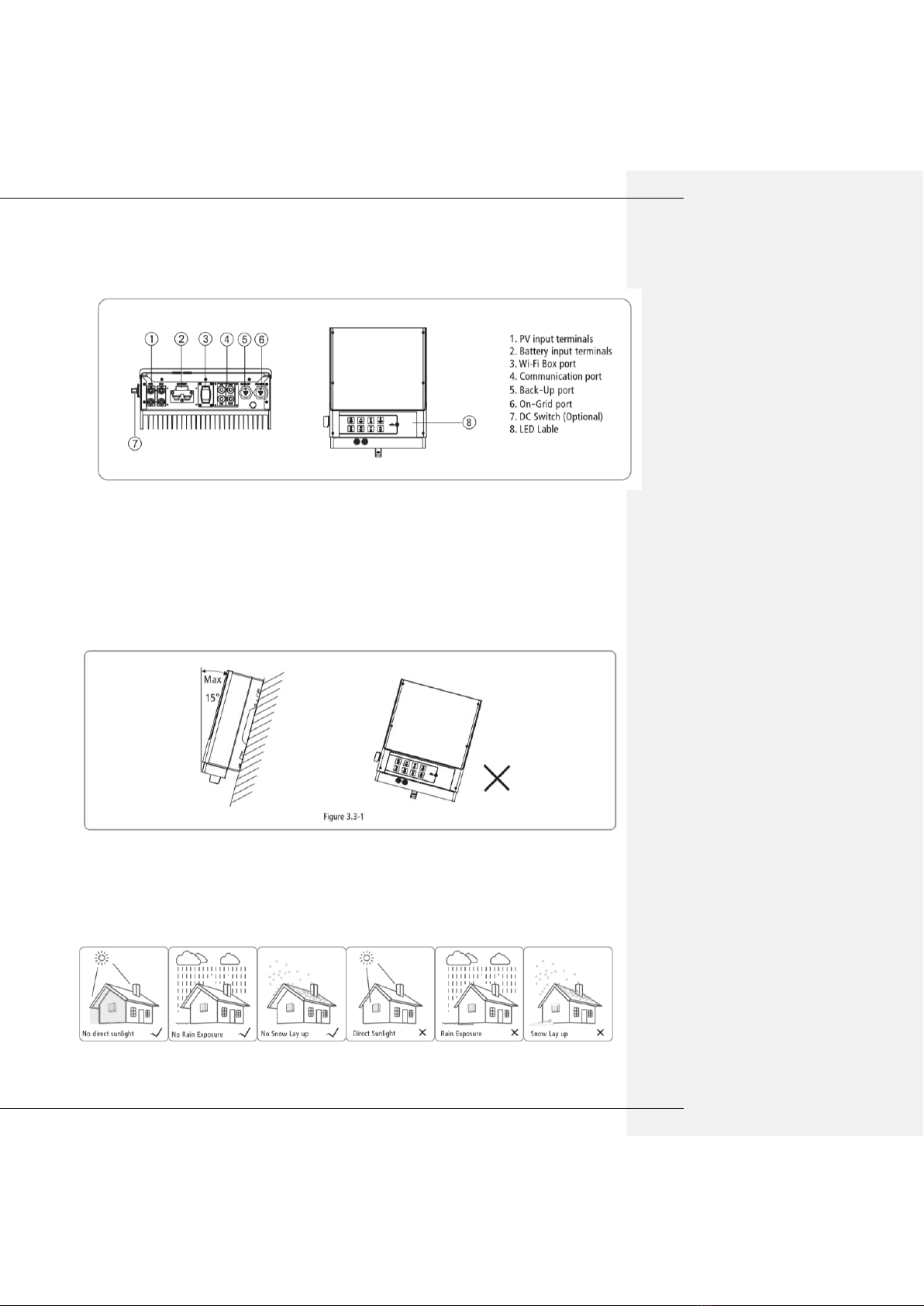
3.2 Product Overview..............................................................................................................................7
3.3 Selecting The Mounting Location......................................................................................................7
3.4 Mounting ..............................................................................................................................................8
4 Electrical Connection...................................................................................................................................9
4.1 PV Connection ......................................................................................................................................9
4.2 Battery Connection............................................................................................................................ 11
4.3 On-grid &Back-up Connection ........................................................................................................ 12
4.4 Communication Connection.............................................................................................................. 13
4.7 Wi-Fi Reset &Reload........................................................................................................................ 15
4.8 DRED Connection............................................................................................................................... 15
4.9 Earth Fault Alarm............................................................................................................................... 16
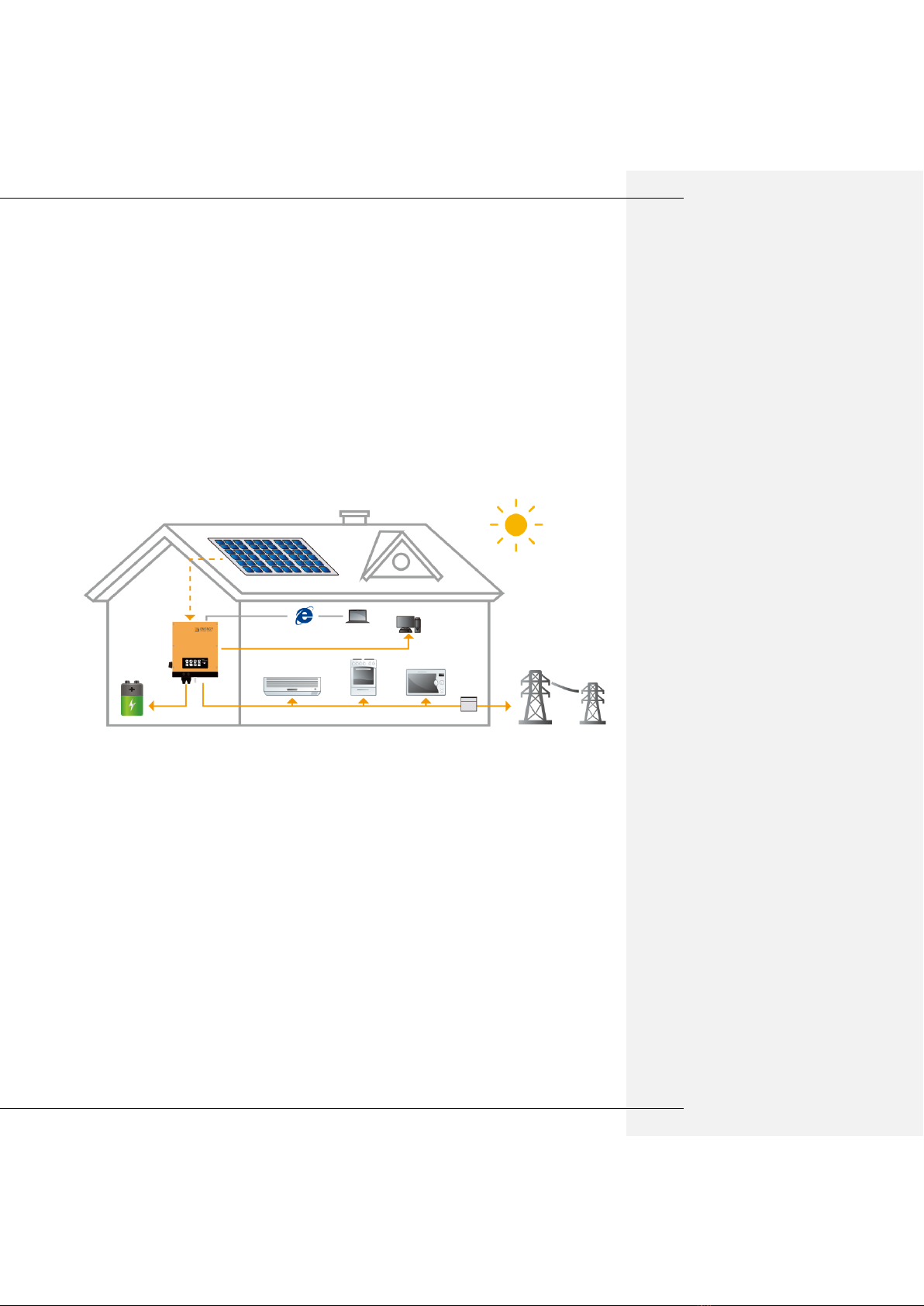
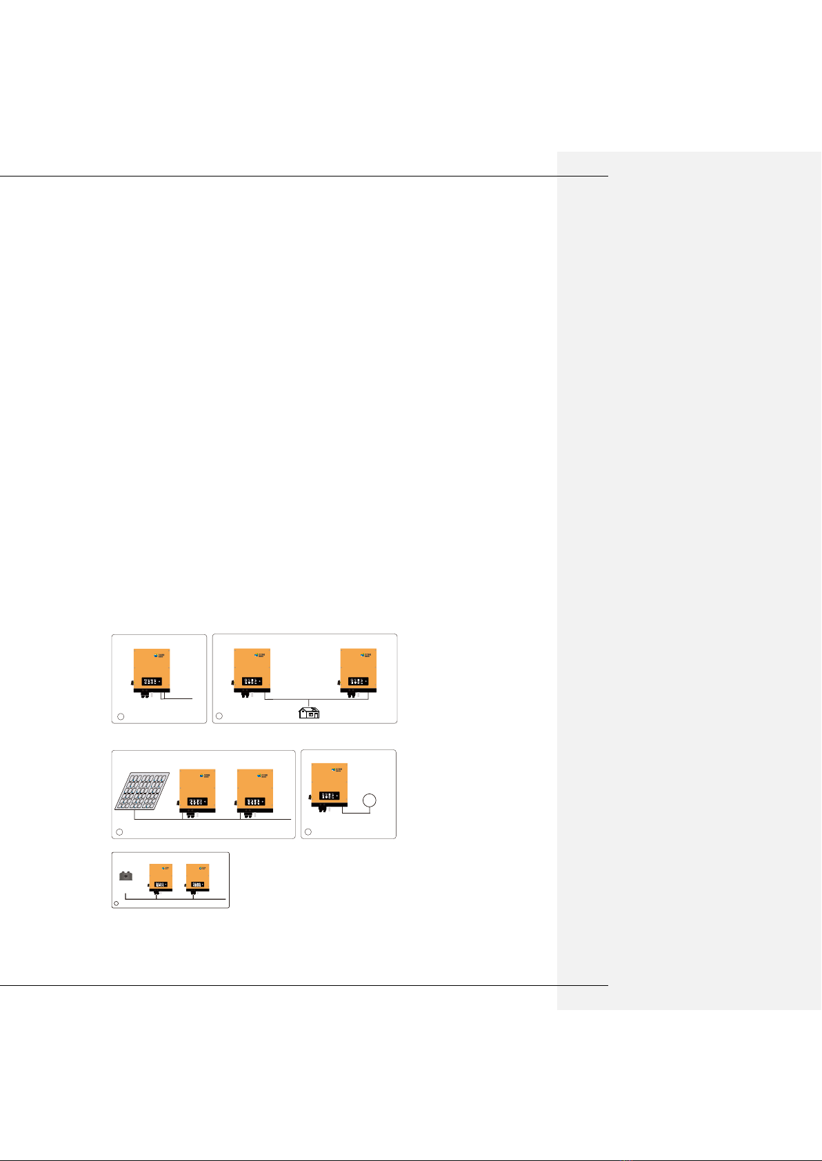
4.10 System Connection Diagram for Normal mode and UPS mode ...................................................... 16
4.11 System Connection Diagram for Off-grid mode.............................................................................. 16
5 GSMART Manager Illustration.................................................................................................................. 17
6 CEI Auto Test/Power limit function Instruction........................................................................................ 17
7 LED Lights Illustration ............................................................................................................................... 17
8 Work Modes ............................................................................................................................................. 18
9 Trouble shooting....................................................................................................................................... 19
10. Error Message........................................................................................................................................ 21
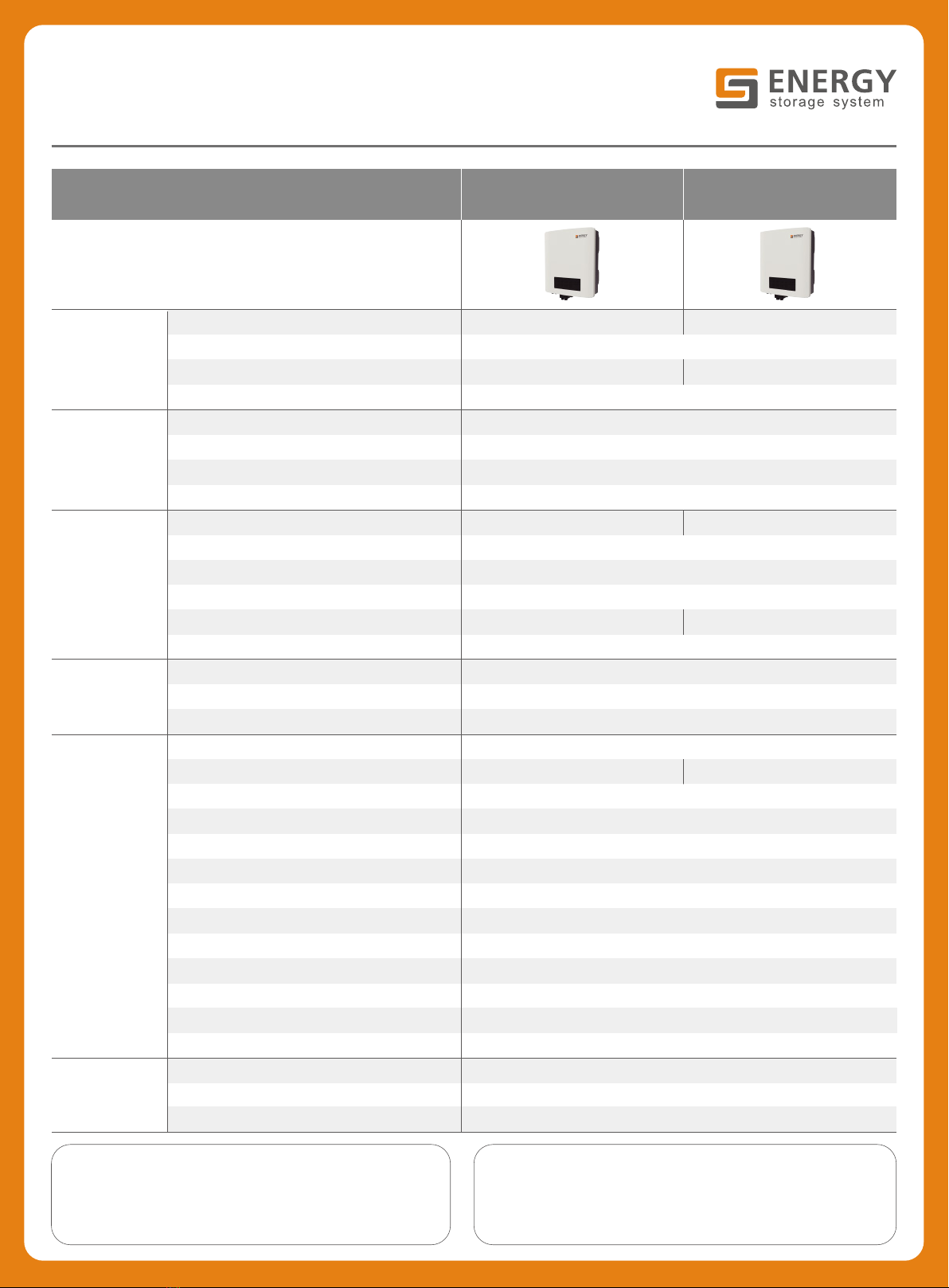
11 Technical Parameters ............................................................................................................................. 22
12 Certificates.............................................................................................................................................. 24
13 Maintenance........................................................................................................................................... 24

08
USER MANUAL
1、introduction:
The GS Energy storage inverter (hybrid) are bidirectional which apply to PV system with battery to storage energy.
Energy produced by the PV system is used to optimize self-consumption; excess energy is used to charge the
batteries, and then feed into the public grid when the PV energy is adequate.
When PV energy output is insufficient to support connected loads, the system automatically discharge energy from
the batteries if battery capacity is abundant. If the battery energy is insufficient to meet own consumption
requirements, electricity will be drawn from the public grid.
The GS Energy storage inverter is designed for both indoor and outdoor use.
2、Important Safety Warning
Before using the inverter, please read all instructions and cautionary markings on the unit and this manual. Store
the manual where it can be accessed easily.
The GS Energy storage inverter of Gsmart(Ningbo) Energy Storage Technology Co.,Ltd (hereinafter referred to as
Gsmart) strictly conforms to related safety rules in design and test.
Safety regulations relevant to the location shall be followed during installation, operation and maintenance.
Improper operation may have a risk of electric shock or damage to equipment and property.

08
2.1 Symbols
DANGER!
“DANGER” indicates a hazardous situation, if not avoid, it may directly result in
death or serious injury.
Caution!
Failing to observe a warning indicated in this manual may result in injury.
Danger of hot surface!
i
Refer to the operating instructions.
Product should not be disposed as household waste.
5min
Inverter will be touchable or operable after minimum 5 minutes of being
turned off or totally disconnected, in case of any electrical shock or injury.
CE MARK
TUV MARK
2.2 Safety
Installation, maintenance and connection of inverters must be performed by qualified personnel, in
compliance with local electrical standards, wiring rules and the requirements of local power authorities
and/or companies.
To avoid electric shock, DC input and AC output of the inverter must be terminated at least 5 minutes
before performing any installation or maintenance.
The temperature of some parts of the inverter may exceed 60℃during operation. To avoid being burnt,
do not touch the inverter during operation. Let it cool before touching it.
Ensure children are kept away from inverters.

08
Do not open the front cover of the inverter. Apart from performing work at the wiring terminal (as instructed
in this manual), touching or changing components without authorization may cause injury to people,
damage to inverters and annulment of the warranty.
Static electricity may damage electronic components. Appropriate method must be adopted to prevent
such damage to the inverter; otherwise the inverter may be damaged and the warranty annulled.
Ensure the output voltage of the proposed PV array is lower than the maximum rated input voltage of the
inverter; otherwise the inverter may be damaged and the warranty annulled.
When exposed to sunlight, the PV array generates dangerous high DC voltage. Please operate according
to our instructions, or it is result in danger to life.
PV modules should have an IEC61730 class A rating.
If the equipment is used in manner not specified by the manufacturer, the protection provided by the may
be impaired.
Completely isolate the inverter before maintaining. Completely isolate the inverter should: Switch off the
DC switch, disconnect the terminal, disconnect the battery terminal, and disconnect the AC terminal.
Prohibit to insert or pull the AC and DC terminal, and the inverter is running.
In Australia, the inverter internal switching does not maintain the neutral integrity, neutral integrity must be
addressed by external connection arrangements like the example proposed in the diagram 4.10.
In Australia, the output of backup side in switchbox should be labeled’ main switch UPS supply’, the output
of normal load side in switchbox should be labeled ’main switch inverter supply’.
Don’t connect GS Energy storage inverter in the following ways:
1) UPS port should not be connected to grid;
2) UPS port should not be connected in parallel;
3) The single PV panel string should not be connected to two or more inverters;
4) On grid or UPS port should not be connect AC generator;
5) One battery(bank) connect with multi inverters.
LINK BATTERY GRID FAULT
SYSTEM MODEL UPS Wi-Fi
Wi-Fi
Resetting
CCBN
storagesp ecia list
!
√
On Grid
X
1
LINK BATTERY GRID FAULT
SYSTEM MODEL UPS W i-Fi
Wi-Fi
Resetting
CCBN
storagesp ecia list
!
√
X
LINK BATTERY GRID FAULT
SYSTEM MODEL UPS Wi -Fi
Wi-Fi
Resetting
CCBN
storagesp ecia list
!
√
UPS
LOAD
UPS
2
LINK BATTERY GRID FAULT
SYSTEM MODEL UPS W i-Fi
Wi-Fi
Resetting
CCBN
storagesp eci alis t
!
√
X
LINK BATTERY GRID FAULT
SYSTEM MODEL UPS W i-Fi
Wi-Fi
Resetting
CCBN
storagesp ecia list
!
√
PV
PV X
3
LINK BATTERY GRID FAULT
SYSTEM MODEL UPS Wi-Fi
Wi-Fi
Resetting
CCBN
storagesp eci alis t
!
√
X
X
6
LINK BATTERY GRID FAULT
SYSTEM MODEL UPS Wi-Fi
Wi-Fi
Resetting
CCBN
storagespecial ist
!
√
LINK BATTERY GRID FAU LT
SYSTEM MODEL UP S Wi-F i
Wi-Fi
Resetting
CCBN
storagespecial i st
!
√
X
BATTERY
X
……
BATTERY
4

08
3 lnstallation
3.1 Packing List
Before installation、please inspect the unit .Be sure that nothing inside the package is damaged. You should
have received the following items inside of package:

08
3.2 Product Overview
3.3 Selecting The Mounting Location
Mounting Location should be selected based on the following aspects:
●The installation method and mounting location must be suitable for the inverter’s weight and dimensions.
●Mount on a solid surface.
●Select a well ventilated place sheltered from direct sun radiation.
●Install vertically or tilted backward by max 15°.The device cannot be installed with a sideways tilt. The
connection area must point downwards. Refer to Figure 3.3.1
●In order to achieve optimal performance, the ambient temperature should be lower than 45℃.
●For the convenience of checking the LED lights and possible maintenance activities, please install the
inverter at eye level.
●Inverters should NOT be installed near inflammable and explosive items. Any strong electro-magnetic
equipment should be kept away from installation site.
●product label and warning symbol shall be clear to read after installation.
●Please avoid direct sunlight, rain exposure, snow lay up when install.
●In consideration of heat dissipation and convenient dismantlement, the minimum clearance around the

08
inverter should be no less than the following value:
3.4 Mounting
Remember that this inverter is heavy! Please be careful when lifting out from the package.
1. Use the wall-mounted bracket as a template and drill 6 holes on the wall. 10mm in diameter and 80mm
deep. Refer to Figure3.4-1.
2 . Fix the wall-mounted bracket on the wall with six expansion bolts in accessory bag.
3 . Carry the inverter by holding the heat-sink two sides. Refer to Figure 3.4-2.
4 . Place the inverter on the wall-mounted bracket. Refer to Figure 3.4-3、Figure 3.4-4.

08
4 Electrical Connection
Hybrid lnverter System Connection Diagram
Note:if equipped with lead-acid battery.do not need to connect③.
4.1 PV Connection
● Before connecting the PV panels, ensure the plug connectors have the correct polarity. lncorrect polarity
could permanently damage the inverter.
● Check the short-circuit of the PV string. The total short-circuit current must not exceed the inverter’s
maximum PV current.
● PV array should not be connected to the grounding conductor.
● Must be use DC plugs in accessory bag.
● The minimum insulation resistance to ground of the PV panels must exceed 19.33kΩ, there is a risk of shock
hazard if the requirement of minimum resistance is not met.
There are two types of DC plugs. Phoenix and MC4 or Amphenol series. Please refer to Figure 4.1-1.

08
Installation instruction of Phoenix please refer to Figure 4.1-2
Installation instruction of MC4 and Amphenol please refer to Figure 4.1-3
An earth wire terminal is set on the right side of the inverter. It can be connected to earth wire. Refer to Figure
4.1-3

08
4.2 Battery Connection
Before connecting to the battery, please install a separate DC breaker (63A) between inverter and battery. This
will ensure the inverter can be securely disconnected during maintenance.
Reversed polarity will damage the inverter!
Be aware of electric shock and chemical hazards!
It is a normal phenomenon that electric arc occurs when connecting battery to the inverter without use a DC
breaker.
It’s very important for system safety and efficient operation to use appropriate cable for battery connection. To
reduce risk of injury, please use the proper recommended cable size. Refer to Figure 4.2-1
Suggestion: if the battery is to be installed indoor, for details please refer to battery manufacture’s user manual.
Suggestion: Batteries must be installed with a distance to each other, details please refer to battery
manufacture’s user manual.
As for the number of cells used, it will be decided by customer’s choice, the choice must comply with the
followed requirement:
the rated voltage is 48V.
Please follow below steps to implement battery connection:
(1) Check the nominal voltage of batteries. The nominal output voltage should meet GSMART product Spec.
(2) Disconnect DC breaker between inverter and battery.
(3) Disconnect screw cap from insulator.
(4) Disconnect waterproof ring from insulator.
(5) Put the cable through the components in this order: screw cap, waterproof ring, insulator, battery cover and
battery terminal.
Refer to Figure 4.2-2.
(6) Compress the terminal head by professional tool and screw down screw cap slight. Refer to Figure 4.2-3,
Figure 4.2-4.

08
(7) Put battery terminal s into the corresponding holes (Red to the positive terminal; Black to the negative
terminal.) and fasten them by screwdriver and spanner (recommended torsion: 6~8N.m), then fasten battery
cover with pan head screws in accessory bag. Refer to Figure 4.2-5, Figure 4.2-6.
(8) Screw down screw cap again.
4.3 On-grid &Back-up Connection
4.3.1 On –grid connection
In order to ensure that the inverter can be safe and reliable to disconnect from grid, please install a circuit
breaker only for inverter on-grid port.
Model
Recommended circuit breaker specifications

08
GS-hybrid-5K
32A
Note:
Multiple inverters are not allowed to share a circuit breaker.
Load is not allowed to connect between the inverter and the circuit breaker.
4.3.2 UPS Load Connection
In order to ensure that the UPS function can be safe and reliable, Please refer to the following content, refer
to left Figure 4.3.2-1.
Inductive load: Single inductive load max power ≤0.7KVA, Total inductive load power ≤1KVA;
For example: Such as Air conditioner, Washer, Electric motor etc is inductive load.
Capacitive Load : Single capacitive load power ≤0.7KVA, Total capacitive load power ≤1.5KVA;
For example: Such as computer, Switch power etc is capacitive load.;
4.3.3 AC Terminal Connection
Installation instruction of WIELAND series please refer to Figure 4.3.3-1.
4.4 Communication Connection

08
There are two pre-made cables connect to GS Energy storage inverter, one cable is 3m which is marked “To
battery”should be connected to Li-battery communication port, the other cable is 10m which marked “To meter”
should be connected to Meter. If not use the battery communication and EM inverter is installed outsides,
please take out the “To battery”cable by remove the communication cover, then put the communication cover
back and install the waterproof terminal.
The “To meter”communication cable attached on inverter can be used for both CAN and RS485
communication protocol.
BMS port is used for communication with lithium battery and can be used for both CAN and RS485
communication protocol.
RS485 port is used for communication with expansion devices.
Color
RS485
Orange/Write
485_A
Orange
485_B
Green/Write
485_A
Blue
NC
Blue/Write
NC
Green
485_B

08
Brown/Write
NC
Brown
NC
4.7 Wi-Fi Reset &Reload
Wi-Fi Reset &Reload only apply to WiFi connection problem, such an ‘Can’t find the inverter WiFi signal’or
‘WiFi’configuration problem’.
Wi-Fi Reset means restarting the Wi-Fi module.
Wi-Fi Reload means making the Wi-Fi module to the default factory setting.
Short press(about 1s) the touch switch, then LED Wi-Fi displays Once a second flicker, Wi-Fi reset is
successful. Refer to Figure
Long press(more than 3s) the touch switch , then Wi-Fi reload is successful. Refer to Figure
4.8 DRED Connection
Connection Procedure:
Put the cable through the components in this order: screw cap, one-hole sealing ring, insulation body and
sheet metal parts.
Pull out the 6-pin terminal from the socket in the cabinet and take off the resistor which is fixed in it. Cable
should be connected an Figure 4.8-1.
Insert the green terminal into the corresponding interior terminal of the inverter. Pull Cable softly to maintain
the cable to be pulled out.
Lock the sheet metal part onto the box and tighten the screw up.
Note:
6-pin terminal is used to make connection to DRED device. If DRED device is not available, please keep it not
connected.
No
Function
1
DRM1/5
2
DRM2/6
3
DRM3/7
4
DRM4/8
5
REFGEN
6
COM/DRM0
1. DRED connection is only available for Australia and Zealand.
2. Supported DRM COMMAND: DRM0, DRM1, DRM2, DRM3, DRM4, DRM5, DRM6, DRM7, DRM8.
批注 [应莉莉1]: 是否有图?
批注 [应莉莉2]: 是否有图?

08
4.9 Earth Fault Alarm
GS Energy storage inverter complies with part2 of IEC62109-2.13.9. when earth fault occurs, the fault indicator
LED on front cover will light on and the buzzer in inverter will keep ringing 1 minute and ring again after half
an hour unless the fault in eliminated.
4.10 System Connection Diagram for Normal mode and UPS mode
4.11 System Connection Diagram for Off-grid mode

08
5 GSMART Manager Illustration
GS Energy storage inverter has no LCD screen, it can be controlled via the APP
software (GSMART Manager). For iOS System, please go to AppStore to search for
“GSMART Manager”, then download and install it. For Android System, please go to
google play to search for “GSMART Manager”, then download and install it. Besides,
it can be also installed by scanning the OR CODE on the back cover of this manual.
When GSMART storage inverter is working, please use mobile devices to select the
SSID of inverter (Factory defaults is Solar-Wi-Fi, and initial password is 12345678. If
any questions, please refer to Wi-Fi Configuration). After accessing inverter’s Wi-Fi
network, you can open the App then configure and monitor the GSMART storage
inverter system.
6 CEI Auto Test/Power limit function Instruction
The PV Auto Test function of CEI is integrated in GSMART Manager App. For the detailed operation of this
function, please check instructions on GSMART Manager App.
The Power limit function can be set by GSMART Manager App. For the detailed operation of this function,
please check instructions on GSMART Manager App.
7 LED Lights Illustration
SYSTEM
MODE
UPS
WIFI
LINK
BATTERY
GRID
FAULT
GREEN
GREEN
GREEN
BLUE
BLUE
BLUE
YELLOW
RED
INDICATOR
STATUS
EXPLANATION
SYSTEM
ON = SYSTEM IS RUNNING
BLINK = SYSTEM IS STARTING
OFF = SYSTEM IS NOT OPERATING
MODE
ON = NORMAL MODE
BLINK1 = UPS MODE
BLINK2 = SELF DEFINE MODE
OFF = OFF GRID MODE
UPS
ON
ON = UPS IS READY
OFF
OFF = UPS IS OFF
WIFI
ON
ON = Wi-Fi CONNECTED
BLINK1
BLINK1 = Wi-Fi SETTING
BLINK2
BLINK2 = Wi-Fi ROUTER PROBLEM
BLINK3
BLINK3 = Wi-Fi SERVER PROBLEM
OFF
OFF = NOT CONNECTED

08
LINK
ON
ON = BMS & METER READY
BLINK1
BLINK1 = BMS COMMUNICATION READY & METER COMMUNICATION FAIL
BLINK2
BLINK2 = METER COMMUNICATION READY & BMS COMMUNICATION FAIL
OFF
OFF = BMS & METER FAIL
BATTERY
ON
ON = BATTERY IS CHARGING
BLINK1
BLINK1 = BATTERY IS DISCHARGING
BLINK2
BLINK2 = BATTERY IS WARNING
BLINK3
BLINK3 = BATTERY IS LOW
OFF
OFF = BATTERY IS DISCONNECTED
GRID
ON
ON = GRID CONNECTED
BLINK1
BLINK1 = GENERATE ENERGY TO GRID
BLINK2
BLINK2 = BUYING ENERGY FROM GRID
OFF
OFF = NO GRID
FAULT
ON
ON = FAULT HAS OCCURRED
BLINK
BLINK = OVER LOAD OF UPS OUTPUT
OFF
OFF = NO FAULT
8 Work Modes
Inverters have the following main work modes based on different conditions.
MODE 1: NORMAL
Energy produced by the PV system priority for local
load, excess energy is used to charge the battery, finally
remaining is delivered to the grid.
LINK BATTERY GRID FAULT
SYSTEM MODEL UPS Wi-Fi
Wi-Fi
Resetting
CCBN
storagespecialist
!
√
MODE 2: UPS
When the grid is actived, Energy produced by the PV
system priority for battery, then local load, finally
remaining is delivered to the grid. When the grid is not
actived, the storage inverter disconnected grid first,
then energy produced by the PV system and batteries
to supplied local UPS load.
LINK BATTERY GRID FAULT
SYSTEM MODEL UP S Wi -Fi
Wi-Fi
Resetting
CCBN
storagespecialist
!
RUN
√
MODE 3: OFF GRID
Energy produced by the PV system priority and battery
supplied local load.
RUN
LINK BATTERY GRID FAULT
SYSTEM MODEL U PS Wi-Fi
Wi-Fi
Resetting
CCBN
storagespecialist
!
RUN
√
MODE 4: SELF DEFINE
This manual suits for next models
5
Table of contents
Popular Inverter manuals by other brands

STEELE PRODUCTS
STEELE PRODUCTS SP-GG750E owner's manual

Lux Power Technology
Lux Power Technology SNA3000 WPV user manual

Southwest Windpower
Southwest Windpower AIR 30 owner's manual

Generac Power Systems
Generac Power Systems Centurion 005223-0 owner's manual

CMP
CMP MSW-2000 manual

Digimax
Digimax UP-8B5N user manual

Huawei
Huawei SUN2000 M5 Series user manual

Toshiba
Toshiba TOSVERT VF-AS1 Series instruction manual

Schumacher Electric
Schumacher Electric XI41DU owner's manual

Solplanet
Solplanet ASW H-S Series user manual

Mecc Alte
Mecc Alte ECO-ECP 4 Operating and maintenance instructions

Veikong
Veikong VFD700 Series Operation manual