GSE GSEM430-144M User manual

Date:2021.06 Doc No:GSE-M-0001 Ver.A
1
Installation guide for module
Purpose of this guide
This guide contains information regarding the installation and safe handling of photovoltaic
modules made by Gazioğlu Solar Enerji San. Ve Tic. A.Ş. hereafter is referred to as
“GSE”.
All instructions should be read and understood before installing the modules. The
installation of modules should conform to all the safety precautions in this guide when
installing the modules. The local standards should also be followed in such installations. If
there are any questions, please contact our sales department for further assistance.
Before installing a photovoltaic system, the installer should be familiar with the mechanical
and electrical requirements for such a system. Keep this guide in a safe place for future
reference (maintenance).
The mechanical and electrical installation of modules should consult the corresponding
laws and regulations, such as electrical method, building law.
Scope
PV modules are ideal for charging storage batteries used to power remote homes,
recreational vehicles, boats, telecommunication systems and other electrical applications.
This manual contains important installation, maintenance and safety information. The word
“module” as used in this manual refers to one or more PV modules.
“GSE” modules are designed to fulfill the criteria of protection class II requirements
according to IEC61730-part1.
The modules are qualified for protection class II: Hazardous voltage (IEC61730: higher
than 50V DC; EN61730: higher than 120V), hazardous power applications (higher than
240W) where general contact access is anticipated (Modules qualified for safety through
EN IEC61730-1 and -2 ).
Disclaimer of liability:
The installation techniques, handling and use of this product are beyond company control.
Therefore, “GSE” does not assume responsibility for loss, damage or expense resulting
from improper installation, handling or misuse.
General Safety Information
Ensure that the module is used only in applications for which it is suitable (see “Installing
Modules”). All work on a PV system (installation, setup, maintenance) must be carried out
only by appropriately qualified and authorized engineers.
The appropriate DIN standards, construction rules and safety instructions must be followed
during installation.
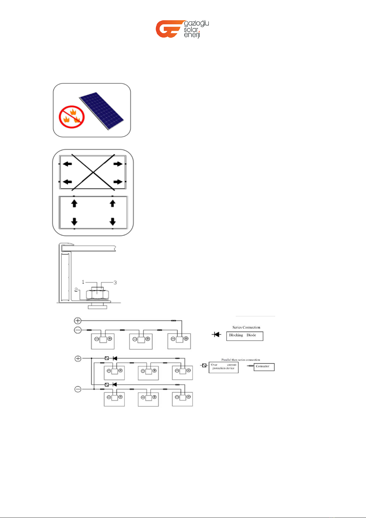
Warning!
PV modules generate electricity as soon as they are exposed to the sunlight. One

Date:2021.06 Doc No:GSE-M-0001 Ver.A
2
module generates the safety extra low volt level, but multiple modules connected in
series (summing the voltage) or in parallel (summing the current) represent a danger.
The following points must be noticed when handling the solar modules to avoid the risk of
fire, sparking and fatal electric shock.
Do not use mirrors or other magnifiers to artificially concentrate sunlight on the modules!
Meaning of crossed –out wheeled dustbin:Do not
dispose of electrical appliances as unsorted municipal
waste, use separate collection facilities.Contact your local
government for information regarding
the collection systems available.If electrical appliances are
disposed of in landfills or dumps, hazardous
substances can leak into the groundwater and get into the food chain, damaging your health and
well
Do not insert any
electrically conducting
materials into the plugs or sockets!
Do not insert any
electrically conducting
materials into the plugs or sockets!
Make sure to use safety equipment (insulated
tools, insulated gloves, etc.) when wiring.
Make sure that we do the connection when the
circuitry is cut off. Do not disconnect under load.
Guarantees the clean connecters has not been
polluted, and the electrical connection and the
mechanical joint is good, to avoid the
generation of electric arc effectively.

Date:2021.06 Doc No:GSE-M-0001 Ver.A
3
being.When replacing old appliances with new ones, the retailer is legally obligated to take back
your old
appliance for disposals at least free of charge.
Unpacking and Storing Modules:
Utmost attention is required when handling the modules. Below marks will be used for
some caution items when unpacking, transporting, and storing the modules:
Do not strike and destroy the module.
Carry modules with both hands. Do not use the
connection socket as a handle;
Don’t lacerate the frame during handling and installing.
Do not stand on the module.
Do not twist the module.Do not twist the module.
Do not mark on the rear of the module using sharp objects.
The accessible PV module surface shall be smooth
and free from sharp edges, burrs, etc.,
Installing Modules:

Date:2021.06 Doc No:GSE-M-0001 Ver.A
4
Please consult local laws and regulations before installing modules and abide by
requirements on building fire protection.
System should be installed by qualified personnel only. The system involves electricity, and
can be dangerous if the personnel are not familiar with the appropriate safety procedures.
The PV modules should be mounted in a location where they will receive maximum sunlight
throughout the year. In the Northern Hemisphere, the modules should face south. And in
the Southern Hemisphere, the modules should face north.
In order to achieve maximum annual yield, optimum
orientation and tilt of PV modules is necessary. Sunlight
shining vertically onto the PV module is the best condition
to generate maximum power.
Artificially concentrated sunlight shall not be directed on
the module.
Make sure the module absorb sunlight without any
shelter to produce the maximum output.
Keeping good ventilation conditions prevents the
modules from getting hot which would reduce
the output performance.
The maximum load on module must not exceed
2.4KN/m2
Site-specific environment loads such as wind and snow
should be taken into account to avoid exceeding the
maximum.
The voltage in series should not exceed the system
voltage nominated by manufacturer.
When designing the system, recommended the maximum
number of modules in parallel should be no more than four

Date:2021.06 Doc No:GSE-M-0001 Ver.A
5
while the maximum number of modules in series no more
than fifteen.
The module must not be installed close to fire or
Flammable materials.
Each module should be fixed at least 8 points on long
frame.
The modules are supported parallel to the surface of the
building wall or roof. And the assembly is to be mounted
over a fire resistant roof covering rated for module’s
application.
Use the existing installation holes instead of drilling
additional holes for installation (Drilling holes shall against
the reliability and warranty of the modules). The
installation and attachment materials (nuts, bolts, etc)
must be corrosion-resistant. Moment of force is 5N·m
for module mounting.
1 Stainless steel M8 nut
2 Stainless steel spring washer
3 Stainless steel M8 t-head bolt
It is suggested to confirm according to the voltage and current actually used in the power
station.

Grounding:
Although the modules are certified to Safety qualification, grounding is nevertheless
to be used. The grounded connection must be made by a qualified electrician.
Connect module frames to each other using cables with cable lugs.
All the junctions on the conductive connection must be fixed. Soldering is not
required.
Date:2021.06 Doc No:GSE-M-0001 Ver.A
A minimum of four clamps must be located in the same colored zone to be certified
to tested value. If one of the clamps is in the different zone the lowest value should
be taken in the account.
Green zone is certified for 2400 Pa Downward
Yellow zone is avalible for 1600 Pa Downward
Red zone should not be used
As the mounting angle increases, downward force will be increased with a
accelerated force such as sliding snow. This increased force will preliminary affect
the module frame. This should be considered when mounting the modules.
6

Date:2021.06 Doc No:GSE-M-0001 Ver.A 7
·The metallic frames must be grounded according to
Article 250 of the U.S. NEC.
·Should provide appropriate engagement through the
anodized layer.
·PV system should work with a reliable lightning protection
system.
1 Stainless steel nut M4
2 stainless steel bolt M4×30
3 stainless steel flat washer M4
4 stainless steel spring washer M4
5 stainless steel serrated washer M4
6 stainless steel slotted washer M4
All ferrous metal in the conductive connection should specially treated, such as by
anodization, spray-painting, galvanization. Stainless steel does not need to be treated.
This protection has been punctured by the grounding device to achieve sufficient
connection.
Wiring
To ensure proper wiring, pay close attention to:
·Correct wiring scheme
When designing the system, avoid forming close loop to minimize risk of an indirect
lighting strike. Check that wiring is correct before starting the generator. If the measured
open circuit voltage (Voc) and short-circuit current (Isc) differ from the specifications,
then there may be a wiring fault.
·Correct connection
The cross section area of cable and the capacity of connector must be selected to suit the
maximum system short circuit current (The area of the cable mated with the connector
is recommended to be 4~6 mm2), otherwise the cable and connector will be overheated
under large current. Please note that the upper limit temperature of cable is120℃ and
the connector is 100℃. The ambient temperature range of cable and connector is -40℃
-90℃.The plug connector has its own polarity. Make sure that the connection is safe and
tight. The plug connector should not receive outer stress. Connectors should only be
used to connect the circuit, but never used to turn the circuit on or off.
·Use of suitable materials
Use cable extensions and plugs that are designed for outdoor applications. Ensure that
they are in perfect electrical and mechanical condition. Only the cables with one
conductor are used.

Date:2021.06 Doc No:GSE-M-0001 Ver.A 8
Ensure that all materials meet the requirements of the system maximum voltage, current,
moisture, and temperature when they expose to sunlight.
Under normal conditions, a photovoltaic module is likely to produce more current and/or
voltage than that reported under standard test conditions.
Accordingly, the values of Isc and Voc marked on this module should be
multiplied by a factor of 1.25 when selecting electricity components voltage ratings,
conductor capacities, fuse type, and type of control components connected to the PV
output.
The maximum series Fuse rating is 20A. And the maximum reverse current is known as
series Fuse rating multiplied by a factor of 1.35.
·Bypass Diodes
When modules in series are shaded partially, it may cause reverse voltage across cells
or modules, this may cause undesirable heating to occur. The use of a diode to bypass
the shaded area can minimize both heating and array current reduction.
All “GSE” modules are equipped with factory installed bypass diodes. The factory
installed diodes provide proper circuit protection for the system. Rating of bypass diodes:
Current 10A; Voltage 50V
·Others
During installation, be sure to tie the cable from the junction box to the mounting
substructure with nylon line, etc. to avoid direct contact of the cable with the back surface
of the module.
Module mounting
GSE’s Limited Warranty for modules is based upon modules being mounted in
accordance with following conditions.
1) Operating conditions
Install GSE Solar Crystalline series modules in the following conditions:
.Operating temperature: -40℃ to +85℃
. Storage temperature: -20℃ to +50℃
. Humidity: below 85RH%
. Altitude: ≤2000m
. Mechanical Load Pressure: 2400Pa (245 Kg/m2)
*Mechanical load bearing specifications of the module is based on GSE Solar mounting
methods. A professional system installer must be responsible for the mechanical load
calculations based on the specific system design.
*The modules have been evaluated by TUV according to IEC61215 for a maximum positive
design loading of below 2400Pa, and negative design loading 1600Pa,with 1.5 times safety
factor.
2) Limited conditions
Installation environment with following conditions should be avoided.
·The installation area with extreme sand and dust damage.

Date:2021.06 Doc No:GSE-M-0001 Ver.A 9
·The installation position with extreme air pollution, chemical vapors, acid rain, and/or soot,
etc.
·The installation place with extreme hail and snow damage.
·The installation location with extreme salt damage.
Checklists:
·All fastenings are tight, secure and free of corrosion.
·All cable connections are secure, tight, clean and free of corrosion.
·Cables are not damaged in any way.
·Verification of the grounding resistivity of metals.
Maintenance and Cleaning
Do not change the PV components (diode, junction box, plug connectors) that can be
serviced by “GSE” authorized distributor or dealer without voiding the warranty.
Given the module a sufficient tilt (at least 15°) to keep one self-clean effect in normal
conditions (rainfall will have a self-cleaning effect). When heavy soiling happened on the
module (which will result in output reductions), we use a gentle cleaning implement (such
as a sponge) and water (from a hose) without clean agents to rinse the modules. Dried
dirt must never be scraped or rubbed, scraping and rubbing module surface will cause
micro-scratching. Periodic inspection must be done for the system.
Module Specifications
Please refer to the latest Module datasheet for more details
MODULE SPECIFICATIONS UNDER STC CONDITION
Model Type Module
Technology
Numb
er Of
Cells
Maximum
Power
(Pmax) [W]
Tolerance ±
5%
Open Circuit
Voltage (Voc)
[V] Tolerance
± 5%
Maximum
Power
Voltage
(Vmp) [V]
Short Circuit
Current
(Isc) [A]
Tolerance
± 5%
Maximu
m Power
Current
(Imp) [A]
Maximu
m Over
Current
Protectio
n [A]
GSEM460-144M
Mono
crystalline
144 460 50.25 42.67 11.41 10.78 20 A
GSEM455-144M
Mono
crystalline
144 455 50.10 42.41 11.37 10.73 20 A
GSEM450-144M
Mono
crystalline
144 450 49.83 42.10 11.34 10.69 20 A
GSEM445-144M
Mono
crystalline
144 445 49.55 41.75 11.31 10.66 20 A
GSEM440-144M
Mono
crystalline
144 440 49.25 41.40 11.28 10.63 20 A
GSEM435-144M
Mono
crystalline
144 435 48.99 41.08 11.25 10.59 20 A

Date:2021.06 Doc No:GSE-M-0001 Ver.A 10
GSEM430-144M
Mono
crystalline
144 430 48.69 40.72 11.22 10.56 20 A
GSEM425-144M
Mono
crystalline
144 425 48.39 40.36 11.18 10.53 20 A
GSEM420-144M
Mono
crystalline
144 420 48.11 40.01 11.15 10.50 20 A
GSEM380-120M
Mono
crystalline
120 380 41.70 34.50 11.56 11.02 20 A
GSEM375-120M
Mono
crystalline
120 375 41.50 34.30 11.48 10.93 20 A
GSEM370-120M
Mono
crystalline
120 370 41.30 34.10 11.37 10.86 20 A
GSEM365-120M
Mono
crystalline
120 365 41.10 33.90 11.28 10.77 20 A
GSEM360-120M
Mono
crystalline
120 360 40.90 33.70 11.20 10.69 20 A
GSEM355-120M
Mono
crystalline
120 355 40.70 33.50 11.10 10.60 20 A
GSEM350-120M
Mono
crystalline
120 350 40.50 33.30 11.02 10.52 20 A
MODULE SPECIFICATIONS UNDER STC CONDITION
Model Type Module
Technology
Numb
er Of
Cells
Maximum
Power
(Pmax) [W]
Tolerance
± 5%
Open Circuit
Voltage (Voc)
[V] Tolerance
± 5%
Maximum
Power
Voltage
(Vmp) [V]
Short Circuit
Current
(Isc) [A]
Tolerance
± 5%
Maximu
m Power
Current
(Imp) [A]
Maximu
m Over
Current
Protectio
n [A]
GSE550-144M Mono crystalline 144 550 49.83 41.33 13.79 13.30 20 A
GSE545-144M Mono crystalline 144 545 49.68 41.18 13.71 13.24 20 A
GSE540-144M Mono crystalline 144 540 49.53 41.03 13.63 13.17 20 A
GSE535-144M Mono crystalline 144 535 49.38 40.88 13.54 13.10 20 A
GSE530-144M Mono crystalline 144 530 49.23 40.73 13.46 13.02 20 A
GSE525-144M Mono crystalline 144 525 49.08 40.58 13.39 12.95 20 A
GSE520-144M Mono crystalline 144 520 48.95 40.43 13.35 12.86 20 A
GSE515-144M Mono crystalline 144 515 48.81 40.33 13.30 12.77 20 A
GSE455-120M Mono crystalline 120 455 41.32 34.42 13.75 13.22 20 A
GSE450-120M Mono crystalline 120 450 41.25 34.21 13.62 13.16 20 A
GSE445-120M Mono crystalline 120 445 41.10 34.06 13.52 13.07 20 A
GSE440-120M Mono crystalline 120 440 40.95 33.91 13.41 12.98 20 A
GSE435-120M Mono crystalline 120 435 40.82 33.85 13.31 12.85 20 A

Date:2021.06 Doc No:GSE-M-0001 Ver.A 11
GSE430-120M Mono crystalline 120 430 40.70 33.86 13.20 12.70 20 A
GSE500-132M Mono crystalline 132 500 45.41 38.11 13.58 13.12 20 A
GSE495-132M Mono crystalline 132 495 45.28 37.95 13.47 13.04 20 A
GSE490-132M Mono crystalline 132 490 45.13 37.89 13.36 12.93 20 A
GSE485-132M Mono crystalline 132 485 45.02 37.77 13.25 12.84 20 A
GSE480-132M Mono crystalline 132 480 44.91 37.65 13.16 12.75 20 A
GSE475-132M Mono crystalline 132 475 44.80 37.52 13.07 12.66 20 A
GSE410-108M Mono crystalline 108 410 37.16 31.01 13.67 13.22 20 A
GSE405-108M Mono crystalline 108 405 37.12 30.98 13.60 13.07 20 A
GSE400-108M Mono crystalline 108 400 37.08 30.92 13.53 12.94 20 A
GSE395-108M Mono crystalline 108 395 37.04 30.86 13.47 12.80 20 A
GSE390-108M Mono crystalline 108 390 37.00 30.80 13.41 12.66 20 A
MODULE SPECIFICATIONS UNDER STC CONDITION
Model Type Module
Technology
Numb
er Of
Cells
Maximum
Power
(Pmax) [W]
Tolerance
± 5%
Open Circuit
Voltage (Voc)
[V] Tolerance
± 5%
Maximum
Power
Voltage
(Vmp) [V]
Short Circuit
Current
(Isc) [A]
Tolerance
± 5%
Maximu
m Power
Current
(Imp) [A]
Maximu
m Over
Current
Protectio
n [A]
GSE260-60P Poly crystalline 60 260 38.06 30.80 9.08 8.44 20 A
GSE265-60P Poly crystalline 60 265 38.18 31.03 9.12 8.54 20 A
GSE270-60P Poly crystalline 60 270 38.30 31.29 9.16 8.63 20 A
GSE275-60P Poly crystalline 60 275 38.46 31.54 9.22 8.72 20 A
GSE280-60P Poly crystalline 60 280 38.85 31.88 9.33 8.78 20 A
GSE285-60P Poly crystalline 60 285 39.01 31.96 9.44 8.92 20 A
GSE290-60P Poly crystalline 60 290 39.20 32.20 9.54 9.01 20 A
GSE295-60P Poly crystalline 60 295 39.36 32.49 9.62 9.08 20 A
GSE300-60P Poly crystalline 60 300 39.48 32.75 9.71 9.16 20 A
GSE310-72P Poly crystalline 72 310 45.51 37.35 8.97 8.30 20 A
GSE315-72P Poly crystalline 72 315 45.69 37.62 8.99 8.38 20 A
GSE320-72P Poly crystalline 72 320 45.86 37.81 9.02 8.46 20 A
GSE325-72P Poly crystalline 72 325 46.04 38.06 9.05 8.54 20 A
GSE330-72P Poly crystalline 72 330 46.36 38.33 9.10 8.61 20 A
GSE335-72P Poly crystalline 72 335 46.43 38.62 9.19 8.68 20 A
GSE340-72P Poly crystalline 72 340 46.73 38.91 9.26 8.74 20 A
GSE345-72P Poly crystalline 72 345 46.98 39.18 9.32 8.81 20 A
GSE350-72P Poly crystalline 72 350 47.23 39.45 9.38 8.87 20 A
GSE355-72P Poly crystalline 72 355 47.38 39.75 9.42 8.93 20 A
GSE360-72P Poly crystalline 72 360 47.53 39.96 9.49 9.01 20 A
GSE365-72P Poly crystalline 72 365 47.68 40.15 9.53 9.09 20 A

Date:2021.06 Doc No:GSE-M-0001 Ver.A 12
MODULE SPECIFICATIONS UNDER STC CONDITION
Model Type Module
Technology
Numb
er Of
Cells
Maximum
Power
(Pmax) [W]
Tolerance
± 5%
Open Circuit
Voltage (Voc)
[V] Tolerance
± 5%
Maximum
Power
Voltage
(Vmp) [V]
Short Circuit
Current
(Isc) [A]
Tolerance
± 5%
Maximu
m Power
Current
(Imp) [A]
Maximu
m Over
Current
Protectio
n [A]
GSEN420-144M
Mono
crystalline
144 420 49.91 41.02 10.68 10.24 20 A
GSEN415-144M
Mono
crystalline
144 415 49.76 40.84 10.60 10.16 20 A
GSEN410-144M
Mono
crystalline
144 410 49.68 40.52 10.53 10.12 20 A
GSEN405-144M
Mono
crystalline
144 405 49.58 40.29 10.49 10.06 20 A
GSEN400-144M
Mono
crystalline
144 400 49.39 40.07 10.42 9.99 20 A
GSEN395-144M
Mono
crystalline
144 395 49.18 39.86 10.38 9.91 20 A
GSEN390-144M
Mono
crystalline
144 390 49.04 39.67 10.34 9.83 20 A
GSEN385-144M
Mono
crystalline
144 385 48.92 39.49 10.30 9.75 20 A
GSEN380-144M
Mono
crystalline
144 380 48.80 39.30 10.26 9.67 20 A
GSEN375-144M
Mono
crystalline
144 375 48.68 39.10 10.22 9.59 20 A
GSEN350-120M
Mono
crystalline
120 350 41.32 35.32 10.36 9.91 20 A
GSEN345-120M
Mono
crystalline
120 345 41.25 34.92 10.32 9.88 20 A
GSEN340-120M
Mono
crystalline
120 340 40.98 34.52 10.28 9.85 20 A
GSEN335-120M
Mono
crystalline
120 335 40.71 34.16 10.24 9.81 20 A
GSEN330-120M
Mono
crystalline
120 330 40.44 33.80 10.20 9.76 20 A
GSEN325-120M
Mono
crystalline
120 325 40.13 33.62 10.16 9.67 20 A
GSEN320-120M
Mono
crystalline
120 320 40.02 33.40 10.12 9.58 20 A

Date:2021.06 Doc No:GSE-M-0001 Ver.A 13
GSEN315-120M
Mono
crystalline
120 315 39.90 33.19 10.08 9.49 20 A
This manual suits for next models
75
Table of contents
Popular Solar Panel manuals by other brands

Schüco
Schüco MSE 210 installation instructions

EGING PV
EGING PV EGM Series General installation manual

Schletter
Schletter SECT installation manual

RM Solar
RM Solar S Class 20 Pro instruction manual

Viessmann
Viessmann Vitosol 100-FM Technical guide

Gasolarxy
Gasolarxy PG-GSP100W Installation guide & manual