GSI Group E Series User manual

PNEG-1993
CE Compliant E-Series
Chain Conveyors - All Models
Installation and Operation Manual -
Original Instructions
PNEG-1993
Version: 2.0
Date: 04-26-16

2 PNEG-1993 CE Compliant E-Series Chain Conveyors - All Models
CE Declaration of Incorporation
EC MACHINERY DIRECTIVE
2006/42/EC
Vendel Park, Erdoalja U1, Biatorbagy, H-2051, Hungary
The GSI Group declares that
GSI E-Series chain conveyors
Models
225 W x 225 T
300 W x 225 T
300 W x 300 T
375 W x 300 T
Excluding:
Meet the following clauses of the Essential Requirements of the Machinery Directive 2006/42/EC.
1.1.2 and sub-clauses principles of safety integration
1.3.2 Risk of break-up during operation
1.3.7 Risk related to moving parts
1.3.8 Choice of protection against risks arising from moving parts
1.3.8.1 Moving transmission parts
1.3.8.2 Moving parts involved in the process (Installer has responsibility to ensure complete compliance
with this clause, as per manual.)
1.3.9 Risks of uncontrolled movements
1.4 Required characteristics of guards and protective devices
1.4.1 General requirements
1.4.2 Special requirements for guards
1.4.2.1 Fixed guards
1.5.4 Errors of fitting
1.5.5 Extreme temperatures
1.5.6 Fire
1.5.7 Explosion
1.5.8 Noise
1.5.9 Vibrations
1.5.13 Emissions of hazardous materials and substances

PNEG-1993 CE Compliant E-Series Chain Conveyors - All Models 3
CE Declaration of Incorporation
EC MACHINERY DIRECTIVE
2006/42/EC
Vendel Park, Erdoalja U1, Biatorbagy, H-2051, Hungary
1.6 Maintenance
1.6.1 Machinery maintenance
1.6.4 Operator intervention
1.7 Information
1.7.1 Information and warnings on the machinery
1.7.1.1 Information and information devices
1.7.2 Warning of residual risks
1.7.4 Instructions
1.7.4.1 General principles for the drafting of instructions
1.7.4.2 Contents of the instructions but not inclusive of sub-clause (u)
1.7.4.3 Sales literature
This declaration applies only to the mechanical elements of the above machines and does not imply
conformity by any other items of equipment fitted to or connected with the above machines.
The equipment above must not be put into service until the machinery into which it is to be incorporated
has been declared in conformity with the provisions of all relevant Directives, nor until these
components have been assembled in the manner recommended in the manufacturers instructions.
Signed :
Name:
Date:
Digitally signed by Frank Ward
DN: cn=Frank Ward, o=Hennock
International Limited, ou,
Date: 2016.04.26 14:39:02 +01'00'

4 PNEG-1993 CE Compliant E-Series Chain Conveyors - All Models
All information, illustrations, photos, and specifications in this manual are based on the latest
information available at the time of publication. The right is reserved to make changes at any
time without notice.

Table of Contents
PNEG-1993 CE Compliant E-Series Chain Conveyors - All Models 5
Contents
Chapter 1 Safety .....................................................................................................................................................6
Safety Guidelines .................................................................................................................................. 6
Cautionary Symbols Definitions ............................................................................................................ 7
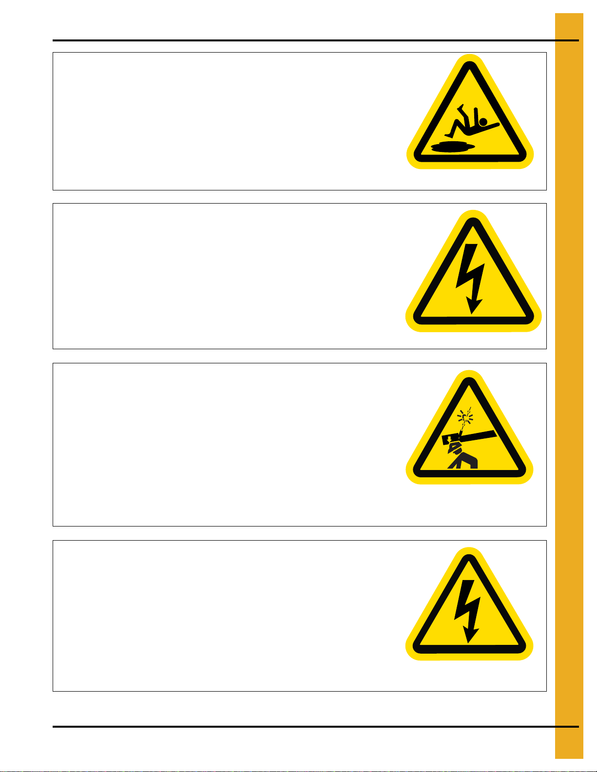
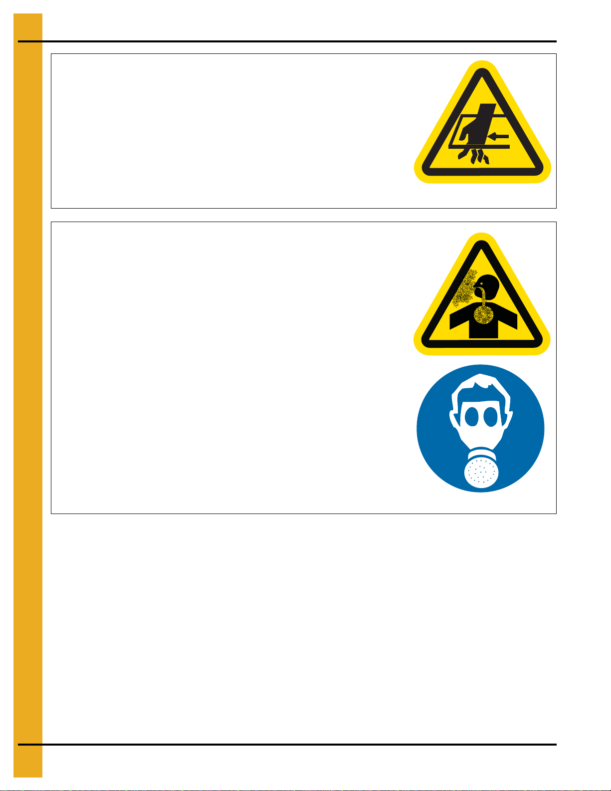
Safety Cautions ..................................................................................................................................... 8
Safety Sign-Off Sheet ......................................................................................................................... 12
Correct Use ......................................................................................................................................... 13
Correct Installation .............................................................................................................................. 14
Guards ................................................................................................................................................ 15
Electrical Safety .................................................................................................................................. 15
Possible Hazards Inside Grain Bins .................................................................................................... 17
Chapter 2 Safety Decals ......................................................................................................................................18
CE Mark and Rating Plate ................................................................................................................... 20
Chapter 3 Installation ..........................................................................................................................................21
Pre-Installation Preparation ................................................................................................................. 21
Head and Tail Identification ................................................................................................................. 22
Assembling an Un-Assembled Intermediate Section .......................................................................... 23
Assemble Conveyor Sections ............................................................................................................. 24
Chain Installation ................................................................................................................................. 28
Gear Motor Installation ........................................................................................................................ 30
Chapter 4 Electric Operated Gate Installation ...................................................................................................31
Overall Head Gate and Intermediate Gate Dimensions ...................................................................... 31
Cut Trough Bottom for Intermediate Gate ........................................................................................... 32
Motor Bracket Installation for Head Gate and Intermediate Gate ....................................................... 33
Limit Switch Installation of Head Gate and Intermediate Gate ............................................................ 34
Install Gate to Trough Bottom of Intermediate Gate and Head Gate .................................................. 36
Flipping the Shaft to Change Gate Drive Side .................................................................................... 37
Slack Chain Detector and Plug Switch ................................................................................................ 38
Chapter 5 Electrical Installation .........................................................................................................................39
Chapter 6 Reducer Lubrication ..........................................................................................................................41
Lubricant Table ................................................................................................................................... 43
Start-Up and Break-In ......................................................................................................................... 44
Chapter 7 Maintenance ........................................................................................................................................45
Chapter 8 Optional Components ........................................................................................................................46
‘Whirlygig’ Motion Sensor .................................................................................................................... 46
Chapter 9 Troubleshooting .................................................................................................................................47
Chapter 10 Warranty ............................................................................................................................................49

6 PNEG-1993 CE Compliant E-Series Chain Conveyors - All Models
1. Safety
Safety Guidelines
Safety guidelines are general-to-specific safety rules that must be followed at all times. This manual is
written to help you understand safe operating procedures and problems that can be encountered by the
operator and other personnel when using this equipment. Save these safety guidelines for future
reference.
As owner or operator, you are responsible for understanding the requirements, hazards, and precautions
that exist and to inform others as required. Unqualified persons must stay out of the work area at all times.
Alterations must not be made to the equipment. Alterations can produce dangerous situations resulting in
SERIOUS INJURY or DEATH.
This equipment must be installed in accordance with the current installation codes and applicable
regulations,whichmustbe carefullyfollowed inall cases. Authorities havingjurisdictionmustbe consulted
before installations are made.
When necessary, you must consider the installation location relative to electrical, fuel and water utilities.
Personnel operating or working around equipment must read this manual. This manual must be delivered
with equipment to its owner. Failure to read this manual and its safety instructions is a misuse of the
equipment.
ST-0001-3

1. Safety
PNEG-1993 CE Compliant E-Series Chain Conveyors - All Models 7
Cautionary Symbols Definitions
Cautionary symbols appear in this manual and on product decals. The symbols alert the user of potential
safety hazards, prohibited activities and mandatory actions. To help you recognize this information, we
use the symbols that are defined below.
DANGER
WARNING
CAUTION
NOTICE
This symbol indicates an imminently hazardous situation
which, if not avoided, will result in serious injury or death.
This symbol indicates a potentially hazardous situation
which, if not avoided, can result in serious injury or death.
This symbol indicates a potentially hazardous situation which,
if not avoided, can result in minor or moderate injury.
This symbol is used to address practices not related to
personal injury.
This symbol indicates a general hazard.
This symbol indicates a prohibited activity.
This symbol indicates a mandatory action.
ST-0005-2

1. Safety
8 PNEG-1993 CE Compliant E-Series Chain Conveyors - All Models
Safety Cautions
Use Personal Protective Equipment
Eye
Protection
Hearing
Protection
Hand
Protection
Head
Protection
Respiratory
Protection
Foot
Protection
Fall
Protection
• Use appropriate personal protective equipment:
• Wear clothing appropriate to the job.
• Remove all jewelry.
• Tie long hair up and back.
ST-0004-1
Follow Safety Instructions
• Carefully read all safety messages in this manual and
safety signs on your machine. Keep signs in good
condition. Replace missing or damaged safety signs.
Be sure new equipment components and repair parts
include the current safety signs. Replacement safety
signs are available from the manufacturer.
• Learn how to operate the machine and how to use
controls properly. Do not let anyone operate without
instruction.
• If you do not understand any part of this manual or
need assistance, contact your dealer.
ST-0002-1

1. Safety
PNEG-1993 CE Compliant E-Series Chain Conveyors - All Models 9
Maintain Equipment and Work Area
• Understand service procedures before doing work. Keep area
clean and dry.
• Never service equipment while it is operating. Keep hands, feet,
and clothing away from moving parts
• Keep your equipment in proper working condition. Replace worn
or broken parts immediately.
ST-0003-1
Install and Operate Electrical Equipment Properly
• Electrical controls must be installed by a qualified electrician and
must meet the standards set by the National Electric Code,
Canadian Electrical Code, and all local and state codes.
• Lock-out power source before making adjustments, cleaning, or
maintaining equipment.
ST-0027-2
Stay Clear of Hoisted Equipment
• Always use proper lifting or hoisting equipment when assembling
or disassembling equipment.
• Do not walk or stand under hoisted equipment.
• Always use sturdy and stable supports when needed for
installation. Not following these safety precautions creates the
risk of falling equipment, which could crush personnel and cause
serious injury or death.
ST-0047-1
Operate Motor Properly
• All electrical connections should be made in accordance with the
National Electric Code (US) or Canadian Electrical Code (CEC).
Be sure equipment and bins are properly grounded.
• Lock-out power before resetting motor overloads.
• Do not repetitively stop and start the drive in order to free a
plugged condition. Jogging the drive in this manner can damage
the equipment and drive components.
ST-0009-2

1. Safety
10 PNEG-1993 CE Compliant E-Series Chain Conveyors - All Models
Stay Clear of Slide Gate
• Keep hands away from slide gate opening. Slide gates can crush
and dismember. Motor can start at any time.
• Lock-out power source before making adjustments, cleaning, or
maintaining equipment.
ST-0049-1
Toxic Fume and Dust Hazard
• Remove paint before welding or heating.
• Avoid potentially toxic fumes and dust. Hazardous fumes can be
generated when paint is heated by welding, soldering, or using a
torch.
• Do all work outside or in a well-ventilated area. Dispose of paint
and solvent properly.
• Remove paint before welding or heating:
— If you sand or grind paint, avoid breathing the dust. Wear an
approved respirator.
— If you use solvent or paint-stripper, remove stripper with soap
and water before welding.
— Remove solvent or stripper containers and other flammable
material from area. Allow fumes to disperse at least 15 minutes
before welding or heating.
ST-0043-1

1. Safety
PNEG-1993 CE Compliant E-Series Chain Conveyors - All Models 11
Fall Hazard
• Ladders, stairways and platforms are for use by competent and
trained personnel only. Do not allow children or other unauthorized
persons to have access to the equipment.
• Access to the equipment must be restricted by the use of security
fencing and lockable gates.
• Lower sections of ladders must be fitted with a lockable safety gate
to prevent unauthorized access.
• Make sure that hot surfaces have had adequate time to cool before
working on or in the equipment.
• Lock out and tag out power supplies and fuel supplies to all
equipment.
• Do not attach lifting equipment to ladders or platforms.
• Do not go outside of the safety rails provided on elevated platforms.
• Donotworkatheightsduringhighwinds,rain,snow,oricestorms.
ST-0056-1
ST-0017-1
Stay Clear of Moving Parts
• Entanglement in rotating sprocket or
moving chain will cause serious injury
or death.
• Keep all guards and covers in place at all
times.
• Lock-out power source before making
adjustments, cleaning, or maintaining
equipment.

1. Safety
12 PNEG-1993 CE Compliant E-Series Chain Conveyors - All Models
Safety Sign-Off Sheet
Below is a sign-off sheet thatcan be used to verify that all personnel have read and understood the safety
instructions. This sign-off sheet is provided for your convenience and personal record keeping.
Date Employee Name Supervisor Name
ST-0007

1. Safety
PNEG-1993 CE Compliant E-Series Chain Conveyors - All Models 13
Correct Use
1. The E-Series Chain Conveyor system is for conveying whole agricultural seeds and grains only. Any
other use is prohibited.
2. It may be equipped to receivegrains from trucks, trailers, other mechanical grain handling equipment.
3. It shall never be filled manually.
4. The conveyor shall never be used with personnel inside the store or bin.
5. Electrical control systems shall be designed to the requirements of the Machinery Directive
2006/42/EC,riskassessmentandshouldbeinaccordancewithEN60204:2006,ENISO13849:2006
or EN 954-1.
6. Never use the E-Series Chain Conveyor with any guards removed.
Figure 1A Example of Enclosed Inlet and Outlet
Incorrect use can be extremely dangerous. Moving chain, paddles, sprockets and
shafts can cause serious injury and kill.
Example enclosed inlet
conveyor feeding elevator.
Example enclosed outlet
feeding conveyor.

1. Safety
14 PNEG-1993 CE Compliant E-Series Chain Conveyors - All Models
7. Power must be OFF, TAGGED and LOCKED before entering grain bin or store or working on
the conveyor. (See Figure 1B.)
Figure 1B
8. Wherever possible run the En-Masse Conveyor empty before stopping it.
9. Never leave the En-Masse Conveyor running unattended.
10. Never allow an untrained person less or one less than 18 years old to operate the
En-Masse Conveyor.
11. Never allow someone under the influence of alcohol or drugs to operate the equipment.
12. Never work alone.
13. Never start equipment until all persons are clear of the grain bin.
14. Keep hands and feet away from all moving parts.
15. Always think before acting. Never act impulsively around the equipment.
Correct Installation
Final installation shall be in accordance with all the safety requirements outlined in this manual and fulfils
the Essential Requirements of the Machinery Directive 2006/42/EC.
1. Supported conveyor at maximum 3 m intervals.
2. Do not fix lift equipment to the conveyor.
3. Do not use the conveyor as a walkway.
4. Provide suitable access ladders, stairs, platforms and walkways to all parts of the conveyor.
5. The conveyor should be installed straight in all directions and horizontal.
6. Never modify the Conveyor from it is original specification.
7. En-Masse inlet and outlet must always be enclosed or all moving parts inaccessible per ISO 13857.

1. Safety
PNEG-1993 CE Compliant E-Series Chain Conveyors - All Models 15
Guards
The following minimum guarding must be fitted at all times.
1. All trough, head and tail covers.
2. Inlet and outlet guarding. (See Page 14.)
3. Belt drive and pulley guard.
Electrical Safety
Motors must be:
1. Selected to suit the length of conveyor (check with GSI).
2. IEC/CE compliant.
3. IP55 minimum.
Control equipment shall include:
1. Fuse protected main power supply.
a. The electrical supply should include earth leakage protection, eg Residual Current Device (RCD)
or Residual Current Circuit Breaker (RCCB), to provide automatic disconnection in the event of
a fault.
2. Lockable main safety disconnect.
a. Disconnects all electrical power.
3. Lockable motor service disconnect.
a. Adjacent to each motor (or group of motors).
b. Disconnects all power to the motors.
4. Emergency stops.
a. Stops all equipment immediately when pressed.
b. Must remain engaged until manually disengaged.
c. Equipment shall not immediately re-start when the emergency stop is re-set.
5. Door safety interlocks - where doors provide access to dangerous machinery. (See Figure 1C
on Page 16.)
a. Immediately stops and prevents re-start of all equipment when the door is open.
b. Equipment shall not immediately re-start when the door in closed.
c. Safety switches shall be SIL3 in accordance with IEC62061:2005.
d. Safety circuits should be Category 3 in accordance with EN 954-1:1997 or PLc in accordance
with ISO 13849-1:2006.

1. Safety
16 PNEG-1993 CE Compliant E-Series Chain Conveyors - All Models
Figure 1C
6. The electrical supply must include a properly designed protective earth system (PE), withconnection
to all exposed conductive parts.
7. All motors shall be connected to protective earth at the terminal provided.
8. The control system shall include,
a. Short circuit protection.
b. Start/stop controls (labelled 1 and 0 respectively).
c. Equipment shall not immediately re-start following reestablishment of power.
d. Motor circuits shall include over current protectionset according to the full load current, stated on
the motor rating plate.
e. Motor thermal protection may also be required.
9. All electrical design, installation and testing must be carried out by a qualified electrical engineer, in
accordance with EU Directives and Standards, local laws and codes.

1. Safety
PNEG-1993 CE Compliant E-Series Chain Conveyors - All Models 17
Possible Hazards Inside Grain Bins
Theinsideof a grain bin, nomatterwhat size, is adangerous location. Grain bins should be kept
locked shut
at all times.
NEVER allow a child or untrained, inexperienced person to enter a grain bin.
Hazards present at any time may include:
Mass flow of grain when filling or emptying which
could draw you in and cause suffocation/burial.
Bridged, crusted or capped grain which could collapse if you stand on it.
It is recommended NEVER to walk on the surface of the stored material.
If grain has stopped flowing,
become bridged, capped or
crusted, the only safe way
to remedy this is from the
outside of the bin.
Exposed machinery such as fans, augers and conveyors
with which you could become entangled.
Hazardous substances such as dust, mould spores,
vapors and gases or low oxygen levels which could
cause respiratory problems.
High temperature combustible material.
It is a recommended additional safety measure to fit grain bin doors and hatches with electrical
interlock switches, to stop all equipment if the door or hatch is opened. However this does not
override the need to lock out power before entering.

18 PNEG-1993 CE Compliant E-Series Chain Conveyors - All Models
2. Safety Decals
Below are the safety warning decals that should be fitted and visible/legible at all times.
DC-2259MGSI Group
1
DC-2259M on head and tail section
On side
(not visible here)
On side
(not visible here)

2. Safety Decals
PNEG-1993 CE Compliant E-Series Chain Conveyors - All Models 19
DC-2258M on intermediate trough sections.
DC-2258M
GSI Group
DC-2258M
GSI Group

2. Safety Decals
20 PNEG-1993 CE Compliant E-Series Chain Conveyors - All Models
CE Mark and Rating Plate
Once the conveyor has been assembled equipped, in accordance with the instructions given in this
manual, the installer or supplier shall make the full Declaration of Conformity and apply the CE mark, in
accordance with the EU Machinery Directive 2006/42/EC. The rating plate, supplied with the drive unit
should be fitted.
Length 176 ft / 53.7 m
Max Chain Speed 167 FPM / 0.85 m/s
Max Capacity 10000 BPH / 350 m3h
Snorm / Scrit 41 RPM / 36 RPM
Ambient Temperature -20°C - +40°C
Tcrit 120°C
SN
Date 26 April 2016
30 HP / 22.5 kW
3 ~
380V (AC)
46 A
50 Hz
GSI HUNGARY KFT
1-93 Budafoki ut, IP-West Building C
Budapest, H-1117
HUNGARY
EN MASSE CHAIN CONVEYOR
100G2114-176
This manual suits for next models
4
Table of contents
Other GSI Group Accessories manuals
Popular Accessories manuals by other brands

Janssen Fritsen
Janssen Fritsen Club Uneven Bars tensioned user manual

Amana
Amana POWER VENT & DOOR KIT installation instructions

DMP Electronics
DMP Electronics 1108 installation guide

Hugo Müller
Hugo Müller GS 4X.00 MOD instruction manual

Optex
Optex OVS-01CC installation instructions

Byron
Byron BY30 manual