GSI Group II Series User manual

PNEG-1043
SeriesII
26"and32"Tall
En-Masse Chain Conveyors
Installation and Operation Manual
PNEG-1043
Date: 12-21-20

2 PNEG-1043 Series II 26" and 32" Tall En-Masse Chain Conveyors
Equipment Information
Use of the Equipment Information page will help you identify your equipment incase you need to call your
dealer or installer. This information should be filled out and kept on record.
Equipment Information
Model Number: ______________________
Serial Number: _______________________
Date Purchased: _____________________
Dealer/Distributor Name and Phone Number:
___________________________________
___________________________________
___________________________________
___________________________________
GSI Material Handling
1004 E. Illinois St.
Assumption, IL. 62510-0020
Phone: 1-217-226-4421
Fax: 1-217-226-4420
www.gsiag.com

Table of Contents
PNEG-1043 Series II 26" and 32" Tall En-Masse Chain Conveyors 3
Contents
Chapter 1 Safety .....................................................................................................................................................4
Safety Guidelines .................................................................................................................................. 4
Safety Sign-Off Sheet ........................................................................................................................... 5
Chapter 2 Safety Decals ........................................................................................................................................6
Head Section Decal Locations .............................................................................................................. 6
Tail Section Decal Locations ................................................................................................................. 7
Chapter 3 General Precautions ............................................................................................................................8
Chapter 4 Inspection .............................................................................................................................................9
Receiving Inspection ............................................................................................................................. 9
Pre-Installation Preparation ................................................................................................................... 9
Chapter 5 Installation ..........................................................................................................................................10
Head and Tail Assembly ..................................................................................................................... 10
Intermediate Trough Section Assembly .............................................................................................. 10
Cover Assembly Installation ................................................................................................................ 12
Inlet Assembly and Installation ............................................................................................................ 12
Drag Chain Assembly Installation ....................................................................................................... 13
Installing Shaft Mount Reducers ......................................................................................................... 14
Torque Arm Bracket Installation .......................................................................................................... 15
Chapter 6 Care and Maintenance .......................................................................................................................16
Storage ................................................................................................................................................ 16
Welding ............................................................................................................................................... 16
Motor ................................................................................................................................................... 16
Support ................................................................................................................................................ 17
Clearance ............................................................................................................................................ 17
Discharge ............................................................................................................................................ 17
Chapter 7 Options ................................................................................................................................................18
Inspection Ports .................................................................................................................................. 18
Plug Relief Door .................................................................................................................................. 18
Slack Chain Assembly ........................................................................................................................ 19
Chapter 8 Optional Carry-Over Bars ..................................................................................................................21
Carry-Over Bars - Reversing Conveyor .............................................................................................. 21
Chapter 9 Troubleshooting .................................................................................................................................22
Chapter 10 Warranty ............................................................................................................................................23

4 PNEG-1043 Series II 26" and 32" Tall En-Masse Chain Conveyors
1. Safety
Safety Guidelines
This manual contains information that is important for you, the owner/operator, to know and understand.
This information relates to protecting personal safety and preventing equipment problems. It is the
responsibility of the owner/operator to inform anyone operating or working in the area of this equipment
of these safety guidelines. To help you recognize this information, we use the symbols that are defined
below. Please read the manual and pay attention to these sections. Failure to read this manual and its
safety instructions is a misuse of the equipment and may lead to serious injury or death.
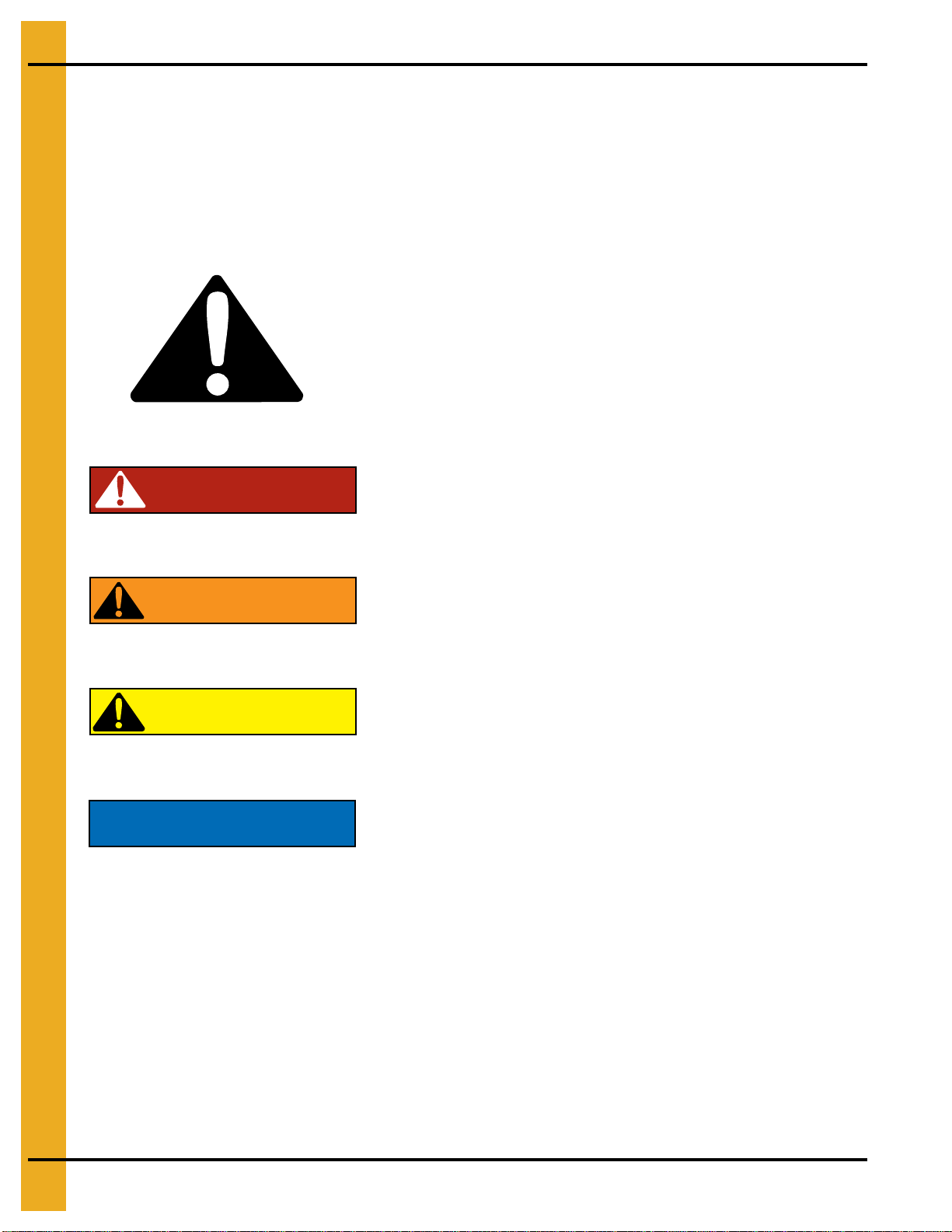
DANGER
WARNING
CAUTION
NOTICE
This is the safety alert symbol. It is used to alert you
to potential personal injury hazards. Obey all safety
messages that follow this symbol to avoid possible
injury or death.
WARNING indicates a hazardous situation which, if not
avoided, could result in death or serious injury.
CAUTION, used with the safety alert symbol, indicates a
hazardous situation which, if not avoided, could result in
minor or moderate injury.
NOTICE is used to address practices not related to
personal injury.
DANGER indicates a hazardous situation which, if not
avoided, will result in death or serious injury.

1. Safety
PNEG-1043 Series II 26" and 32" Tall En-Masse Chain Conveyors 5
Safety Sign-Off Sheet
As a requirement of O.S.H.A., it is necessary for the employer to train the employee in the safe operating
and safety procedures for this auger. This sign-off sheet is provided for your convenience and personal
record keeping. All unqualified persons are to stay out of the work area at all times. It is strongly
recommended that another qualified person who knows the shut down procedure be in the area in the
event of an emergency.
Date Employee Name Supervisor Name

6 PNEG-1043 Series II 26" and 32" Tall En-Masse Chain Conveyors
2. Safety Decals
Head Section Decal Locations
DC-972
WARNING
Moving parts can crush
and cut. Keep hands
clear. Do not operate
without guards in place.
Failure to do so could
result in serious injury.
GSI Group 217-226-4421
Moving parts can
crush and cut.
Do not operate with
guard removed.
Disconnect and lockout
power before servicing.
Keep hands clear
.
DC-997
The GSI Group 217-226-4421
DANGERDANGER
WARNING
EXPOSED CONVEYORS
Moving parts can cause
serious injury.
Lockout power before
removing covers or inspection
door.
GSI Group Inc. 217-226-4421 DC-1230
Moving parts can
crush and cut.
Do not operate with
guard removed.
Disconnect and lockout
power before servicing.
Keep hands clear.
DC-996The GSI Group 217-226-4421
WARNING
1
2
3
4
Decal 3 outside
Decal 4 inside
Decal 3 Outside
Decal 4 Inside

2. Safety Decals
PNEG-1043 Series II 26" and 32" Tall En-Masse Chain Conveyors 7
Tail Section Decal Locations
DC-972
WARNING
Moving parts can crush
and cut. Keep hands
clear. Do not operate
without guards in place.
Failure to do so could
result in serious injury.
GSI Group 217-226-4421
Moving parts can
crush and cut.
Do not operate with
guard removed.
Disconnect and lockout
power before servicing.
Keep hands clear
.
DC-997
The GSI Group 217-226-4421
DANGER
DANGER
Moving parts can
crush and cut.
Do not operate with
guard removed.
Disconnect and lockout
power before servicing.
Keep hands clear.
DC-996
The GSI Group 217-226-4421
WARNING
1
Decal 3 Outside
Decal 4 Inside
3
4

8 PNEG-1043 Series II 26" and 32" Tall En-Masse Chain Conveyors
3. General Precautions
1. Read and understand the Operator’s manual BEFORE operating the unit.
2. Keep all safety shields and devices in place.
3. Keep all covers in place.
4. Make certain everyone is clear of the equipment before operating.
5. Keep hands, feet and clothing away from moving parts.
6. Shut OFF and lock out all power to adjust, service, clean or unclog the unit.
7. Keep off the equipment at all times.
8. Keep children, visitors and all untrained personnel away from the machine
when in operation.
9. Do not operate electric motor equipped units until motors are properly grounded.
10. Disconnect power on electrical driven units before resetting motor overloads.
11. Do not repetitively stop and start the drive in order to free a plugged condition.
“Jogging” the drive in this manner can damage the conveyor and/or
drive components.
CAUTION

PNEG-1043 Series II 26" and 32" Tall En-Masse Chain Conveyors 9
4. Inspection
Receiving Inspection
Carefully inspect the shipment as soon as it is received. Verify that the quantity of parts or packages
actually received corresponds to the quantity shown on the packing slip. Any discrepancies should be
clarified immediately. Please remember that any damage or missing parts must be noted on the bill of
lading at the time of delivery. Report any damage or shortage to the delivering carrier as soon as possible.
GSI’s responsibility for damage to the equipment ends with acceptance by the delivering carrier.
Save all paperwork and documentation furnished with any of the en-masse conveyor components.
Pre-Installation Preparation
Familiarize yourself thoroughly with this manual and all the conveyor parts. Read the Operator’s manual
and all safety signs before using or servicing equipment. Taking the time to do so will aid in the assembly
of the conveyor.
Remove all banding and crating material. Arrange the conveyor components so that they are
easily accessible.
Locate sturdy items to serve as blocking. (i.e. wood blocks, saw horses, etc.) Blocking is used to support
the conveyor sections above the ground to help in assembly. Locate and place the conveyor sections
on the blocking in order, starting with the head section and concluding with the tail section.

10 PNEG-1043 Series II 26" and 32" Tall En-Masse Chain Conveyors
5. Installation
Head and Tail Assembly
The head and tail sections of the chain conveyor are shipped pre-assembled direct from the factory.
Intermediate trough sections may come factory pre-assembled or unassembled. The order will serve
as a reference to how the trough section will arrive. If you have any questions, please refer to the
order confirmation.
Figure 5A Head Assembly Figure 5B Tail Assembly
Intermediate Trough Section Assembly
Figure 5C Typical Intermediate Trough Section Assembly

5. Installation
PNEG-1043 Series II 26" and 32" Tall En-Masse Chain Conveyors 11
An en-masse conveyor may be purchased with unassembled trough sections. The following
recommendations may prove useful in the assembly.
Before assembling conveyor trough sections together, remove the covers. Covers should be stored in a
protected area in order to minimize any possible damage. Remember to retain factory shipped hardware
for conveyor cover installation.
Take a moment to familiarize yourself with the trough assembly. Install the slide rail returns so that the
wide ends of the rail returns face away from the discharge end of the conveyor. The narrow end of the rail
returns, therefore, will face toward the discharge end.
Intermediate trough sections are supplied in standard ten feet (10') lengths. Depending on the application
andindividualspecificationshowever, shortersectionsmayberequiredtoaccommodatea desired overall
length.
Lay bottom plate weldment on blocking material. Next, loosely attach side weldments to bottom plate
with 3/8'' hardware provided. Then fasten slide rail return weldment to intermediate sides with the
1/2" hardware.
NOTE: It is critical for straightness of the conveyor that the sides and bottom flanges are aligned flush.
Also, it is important that the inside dimensions of the box are equidistant in measurement
from side-to-side both top and bottom of the trough box (Dimension A = Dimension B).
(See Figure 5D.)
Figure 5D End View of Trough Section (Liners not shown for clarity.)
After making sure the flanges are aligned, tighten all hardware on the trough section. Abrasion Resisting
(A.R.) liners are installed with the 3/8" flat countersunk hardware provided. Adequately tighten liners to
conveyor sides. Make sure that the countersunk hardware is not protruding above the surface of the
A.R. liners.
During assembly of each trough section to the next section, carefully inspect each flange joint to ensure
that the inside bottom and side surfaces of the troughs are flush. A chalk line is helpful during this phase
of the assembly to ensure the proper alignment of the trough surfaces. The maximum run-out in any
direction should be ±1/4''. Proper alignment minimizes wear on flights and other potential damage to the
conveyor. Make sure the conveyor is level in horizontal applications.
Proceed by attaching the head and tail assemblies using the same alignment procedures and precautions
noted in the preceding paragraph.

5. Installation
12 PNEG-1043 Series II 26" and 32" Tall En-Masse Chain Conveyors
Cover Assembly Installation
Fasten covers to the en-masse conveyor with the 3/8" and 1/2" hardware provided. Adequately tighten the
1/2" bolts and nuts so that the vertical cover seams are in tight contact with each other.
When an inlet is on the conveyor, a cover section may have to be cut accordingly to accommodate the
inlet. For installation of an inlet, see inlet assembly and installation below.
Inlet Assembly and Installation
One inlet is typically provided per conveyor. GSI’s recommendation for inlet installation includes a
minimum distance of no less than 6" between the closest edge of the inlet and the tail assembly.
(See Figure 5E.)
The inlet can be attached with continuous weld seams. If intermittently welded, it is important to use
caulking or sealing around the inlet area in order to seal the unit.
Similarly, GSI recommends that if inlets are welded onto the conveyor, this procedure should be done
before the installation of motor and/or other electrical devices. If the owner fails to follow this precaution,
the owner assumes all risks associated with this installation.
Figure 5E
Ref # Description
AHead Discharge End
B Standard Inlet
CTail End

5. Installation
PNEG-1043 Series II 26" and 32" Tall En-Masse Chain Conveyors 13
Drag Chain Assembly Installation
All chain supplied with new conveyors, regardless of type, will be installed in a similar manner. Correct
total chain length has been determined for the installation by GSI. The conveyor drag chain is shipped
in approximate ten feet (10') lengths with an additional pre-cut short section, if necessary (refer to
packing list). If welded chain (WH132, WH155 or WH157) has been supplied with the conveyor, a
minimum of five feet (5') of chain with cottered pin connectors will be supplied. These pin connectors
and links may be removed as necessary for chain take-up. The chain may be installed at any time during
conveyor assembly.
It is recommended however, that you position the chain over the slide rail returns and the sprockets in the
head and tail assemblies. The UHMW wear pads should be in front of the welded chain flights in the
direction of chain travel (A). (See Figure 5F.) Connect chain lengths together with connecting links
and/or pins.
Figure 5F
Tighten the drag chain assembly using the take-up screws located on each side of the tail section or on
the take-up head. The chain should be able to be lifted slightly when sufficiently tightened. After the chain
is tight, check that the head and tail shaftsare square to the box sides. If the shafts are not square, loosen
the tighter of the two take-up screws until the shafts are square. Lock the take-up screws by tightening the
jam nuts.
Rotate the chain, now on the sprockets, at least one complete revolution. Check to see that the chain and
its wear pads are not catching on flanges or rubbing on the trough liners. Ensure a break-in period whereby
the chain is allowed to run and seat itself. After running it for an adequate period of time, stop the machine,
disconnect and lock out the power source. Re-tighten as necessary and remove any excess chain portions.
Repeat this process as necessary.
Ref # Description
ADirection of Chain Travel Bottom Run

5. Installation
14 PNEG-1043 Series II 26" and 32" Tall En-Masse Chain Conveyors
Installing Shaft Mount Reducers
Assemble torque arm bracket to conveyor per installation instructions found on Page 15.
To aid in the installation of the reducer onto the shaft, remove any protective coating film from shaft.
Slide the reducer onto the drive shaft extending from the side of the conveyor head section. Using the
instructions and hardware supplied with the reducer, assemble it to the conveyor drive shaft.
Assemble motor mount to the reducer. Refer to installation instructions provided with motor mount.
Installthe rear panel of the drive guard before mounting the sheaves. The rear panelhas four (4) mounting
brackets with slotted holes. Attach the lower brackets to the matching reducer assembly bolts. Attach the
upper brackets to the matching holes in the front motor mount support.
Assemble the V-belt driven sheave to the input shaft of the shaft mount reducer. Slide the sheave hub
onto the shaft and insert the square key. Attach the hub sheave using the supplied retaining screws.
The retaining screws pass through the non-threaded holes of the hub and into the sheave. Align the driver
and driven sheaves and tighten the retaining screws. During tightening, it is possible for the sheave to
move out of alignment orbecome out of square. For maximum V-beltlife,thedrivensheaveshouldremain
bothperpendicular to thedrive shaft and alignedwiththe drive sheave.Slipthe V-belts over boththe driver
and driven sheaves.
Figure 5G
Ref # Description
ASpan
B Belt deflection 1/64” per inch of span
CForce
DMotor
EReducer

5. Installation
PNEG-1043 Series II 26" and 32" Tall En-Masse Chain Conveyors 15
Adjustment of V-belt tension is achieved by tightening the hex nuts located on the four (4) jackscrews of
the motor base. Adjust motor base equally at all four (4) jackscrews to maintain shaft alignment. Belts are
designed to fit loose upon installation. When the V-belt tension is correct, tighten the top nut on the
jackscrews to lock the motor base in position. Proper tension is 1/64" of deflection per one inch (1") of
sheave centers on one side of belt, centered between sheaves.
NOTE: Too much tension shortens belt life. Check belt tension frequently during the first 24-48 hours
of operation.
Install the front drive guard panel over the four (4) corner mounting studs. Secure with washers and
nuts provided.
Fill the shaft mount reducer with the manufacturer’s recommended oil. A list of recommended oil can be
found in the gear reducer instructions.
Torque Arm Bracket Installation
When a drive package is ordered with the conveyor system, a torque arm bracket is provided.
The torque arm bracket is pre-punched for ease of installation on the unit. Begin installation of this option
by first determining the location of the torque arm bracket relative to the range of extension allowed by the
shaft mount reducer’s torque arm. The bracket will extend on the same side of the conveyor as the head
shaft. Remove the 5/8" bolts necessary from the bottom of the conveyor head bottom plate.
Figure 5H Torque Arm Bracket
Set the torque arm bracket in place and attach with the 5/8" hardware previously removed from the
bottom plate of the conveyor. Four (4) 5/8" bolts and nuts are required to fasten the torque arm bracket to
the conveyor.
Install shaft mount reducer to head shaft per instructions on Page 14.
Next, match the size of the hardware to the reducer manufacturer’s torque arm. Use this hardware to
attach the torque arm to the bracket. Adequately tighten all hardware.

16 PNEG-1043 Series II 26" and 32" Tall En-Masse Chain Conveyors
6. Care and Maintenance
The care and maintenance section is provided to help extend the useful life of the unit. Like all equipment,
the useful life of the conveyor is greatly reduced if not used wisely and well maintained.
Please follow the next few simple steps to ensure the safety and longevity of the equipment.
1. Check all bearings and moving parts daily during use.
2. Lubricate bearings according to bearing manufacturer’s recommendations.
3. Follow manufacturer’s recommendations for gear reducer lubrication and maintenance.
4. Inspect the V-belts periodically for proper tension and wear. V-belts should be replaced as
necessary. If replacement or tension adjustment is required, please refer to the shaft mount reducer
assembly section on Page 14.
5. The drag chain and sprockets should be checked periodically for wear, damage and proper
adjustment. Any broken or bent paddles should be replaced or straightened. Should adjustment or
replacement of the drag chain be required, refer to assembly section on Page 13.
Storage
If the unit is to be inactive for an extended period, the following procedures are recommended.
1. Thoroughly clean the unit.
2. Loosen the drag chain tension. Doing so relieves the stress placed on the bearings and shafts of the
drive and tail sections.
3. Lubricate drag chains, shafts and drive components with a good grade of light machine oil.
Welding
Welding on or to the conveyor may cause damage to both the conveyor and its electrical system.
If welding is necessary, measures should be taken to protect the conveyor. Should it be necessary to
fasten anything to the conveyor permanently, careful consideration should be given to methods of
maintenance, removal and replacement of the conveyor and/or its parts. (Please refer to Inlet Installation
for GSI recommended guidelines.)
Motor
Connect the conveyor motor to a power source according to the motor manufacturer’s instructions and
recommendations. To avoid injury it is recommended that a certified electrician perform the motor wiring.
A shut off switch should be placed near the motor so that the system may easily be shut down to help
prevent accidents during maintenance. It is important to check proper motor shaft rotation before installing
drive belts.
Before any maintenance is performed to the conveyor, shut OFF and lock out power
to prevent accidental start-up.
WARNING

6. Care and Maintenance
PNEG-1043 Series II 26" and 32" Tall En-Masse Chain Conveyors 17
Support
GSI’s recommended general guidelines in this area include adequate support for the conveyor assembly
to be installed at intervals no greater than 10 feet (10'). It is recommended that supports be installed at
vertical portions of flanges,leaving bottoms of trough sections clear. By attaching supports in this manner,
the removable bottoms are unobstructed for easy replacement. Support legs are available as an option.
Clearance
A clearance of at least the width of the conveyor is recommended on all sides of the unit. While clearance
may be acceptable, serious consideration must be given to methods of maintenance, removal and
replacement of the conveyor and/or its parts.
Discharge
The standard conveyor is constructed with one discharge located at the drive end. If intermediate
discharges are to be used, the location(s) must be determined prior to proceeding with the conveyor
assembly. Intermediate discharges cannot be installed over a trough joint; therefore, it may be necessary
to position a shorter trough section to serve as a spacer in order to accommodate the placement of the
discharge(s) where they are required.
The owner assumes all responsibility for any alterations to the equipment.

18 PNEG-1043 Series II 26" and 32" Tall En-Masse Chain Conveyors
7. Options
Inspection Ports
After determining location(s) for the inspection port(s) on conveyor, cut an 11-3/4" square hole in the cover
for each inspection port. Cut the square opening so that it is centered over the peak of the conveyor cover.
Position the inspection port over the square hole until its frame is flush to the cover. Weld inspection port
to conveyor cover. Additional caulking may be required so that water will shed from the inspection port.
Figure 7A
Plug Relief Door
GSI Series 2 26" and 32" tall en-masse conveyors come equipped with a head discharge plug relief door
as a standard feature. A NEMA 4 heavy duty limit switch is standard on the relief door.
However, in extremely dirty, dusty conditions and/or in enclosed environments, a NEMA 9 heavy duty limit
switch should be used on the plug relief door. The NEMA 9 limit switch is available as an added option.
The optional NEMA 9 limit switch (GSI part # CE-00504) attaches to the same universal bracket on the
front of the head assembly as the standard NEMA 4 limit switch. The same hardware is usedfor both limit
switches.
NOTE: The limit switch bracket must be oriented as shown for proper engagement between limit switch
and plug relief door.
Attach the bracket to the hood cover with two (2) 5/16" bolts and nuts where two (2) pre-punched
holes are located. Two (2) pairs of pre-punched holes are provided on the removable head hood
cover-one (1) pair on the left side and one (1) pair on the right side of hood cover. Next, use two (2)
#10 machine screws, nuts and washers to fasten the limit switch to the bracket. The limit switch can be
installed either to the left or to the right. Do not tighten these machine screws at this time.
Adjust the limit switch so that the actuator arm keeps sufficient tension against the plug relief door. After
the limit switch is properly positioned, tighten the two (2) machine screws.

7. Options
PNEG-1043 Series II 26" and 32" Tall En-Masse Chain Conveyors 19
Plug Relief Door (Continued)
Figure 7B
Slack Chain Assembly
The GSI Group offers a slack chain detector system as an option for its 26" and 32" tall series II
en-masse conveyors. Depending on working conditions and/or environment, either a NEMA 4 or a
NEMA 9 limit switch is available.
Begin installation of optional slack arm assembly by first cutting a 12" x 5" rectangular hole in the head
section cover. (See Figure 7C on Page 20.)
Next, center the slack chain assembly over the rectangular opening. Mark the locations for the
four (4) 7/16" diameter holes. Temporarily remove the slack chain assembly, and drill the four (4)
7/16" diameter holes.
Before attaching slack chain assembly to the conveyor, apply sealant to bottom surfaces of slack
chain assembly.
Fasten slack chain assembly to conveyor with 3/8" hardware. See Figure 7C on Page 20 regarding
direction of slack chain assembly on the conveyor.
After installation, check that the clearance between the UHMW paddle in the slack chain assembly and
the UHMW flights on the chain is approximately 1/2" to 3/4". Adjust if necessary.
Ref # Description
AStandard Plug Relief Door Limit Switch
B Optional NEMA 9 Limit Switch GSI (CE-00504)

7. Options
20 PNEG-1043 Series II 26" and 32" Tall En-Masse Chain Conveyors
Slack Chain Assembly (Continued)
Figure 7C
Ref # Description
ATop Mount Slack Chain with NEMA 4 Limit Switch
B Top Mount Slack Chain with NEMA 9 Limit Switch
CØ 7/16" Typical
D Apply sealant to underside all around before attaching to conveyor.
Other manuals for II Series
1
Table of contents
Other GSI Group Accessories manuals
Popular Accessories manuals by other brands

PCB Piezotronics
PCB Piezotronics 208C03 Installation and operating manual

Electra
Electra e2.3 instruction manual

HeimVision
HeimVision Greets 1 user manual

Tendercare
Tendercare Snappi Sun Hood and Transparent Rain Shield instructions

Markilux
Markilux 6000 installation instructions

Panasonic
Panasonic EX-10 Series user manual