GSI Group PNEG-1204 User manual

PNEG-1204
Enclosed Belt Conveyor
Installation and Operation Manual
PNEG-1204
Date: 12-21-20

2PNEG-1204 Enclosed Belt Conveyor
Use of the equipment information page will help you identify the equipment in the case that you need to
call your dealer or installer. This information should be filled out and kept on record.
Equipment Information
Model #:___________________________________________
Serial #:____________________________________
Date Purchased:____________________________________
Dealer/Distributor Name and Phone #:___________________________________________
Material Handling
1004 E. Illinois St.
Assumption, IL. 62510
Phone: 1-217-226-4421
All information, illustrations, photos, and specifications in this manual are based on the latest
information available at the time of publication. The right is reserved to make changes at any
time without notice.

Table of Contents
PNEG-1204 Enclosed Belt Conveyor 3
Contents
Chapter 1 Introduction ..........................................................................................................................................4
Chapter 2 Safety .....................................................................................................................................................5
Safety Guidelines .................................................................................................................................. 5
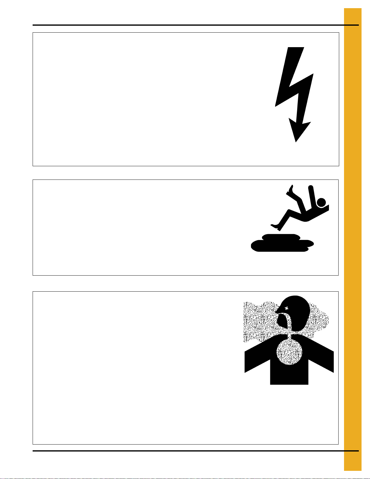
Safety Instructions ................................................................................................................................. 6
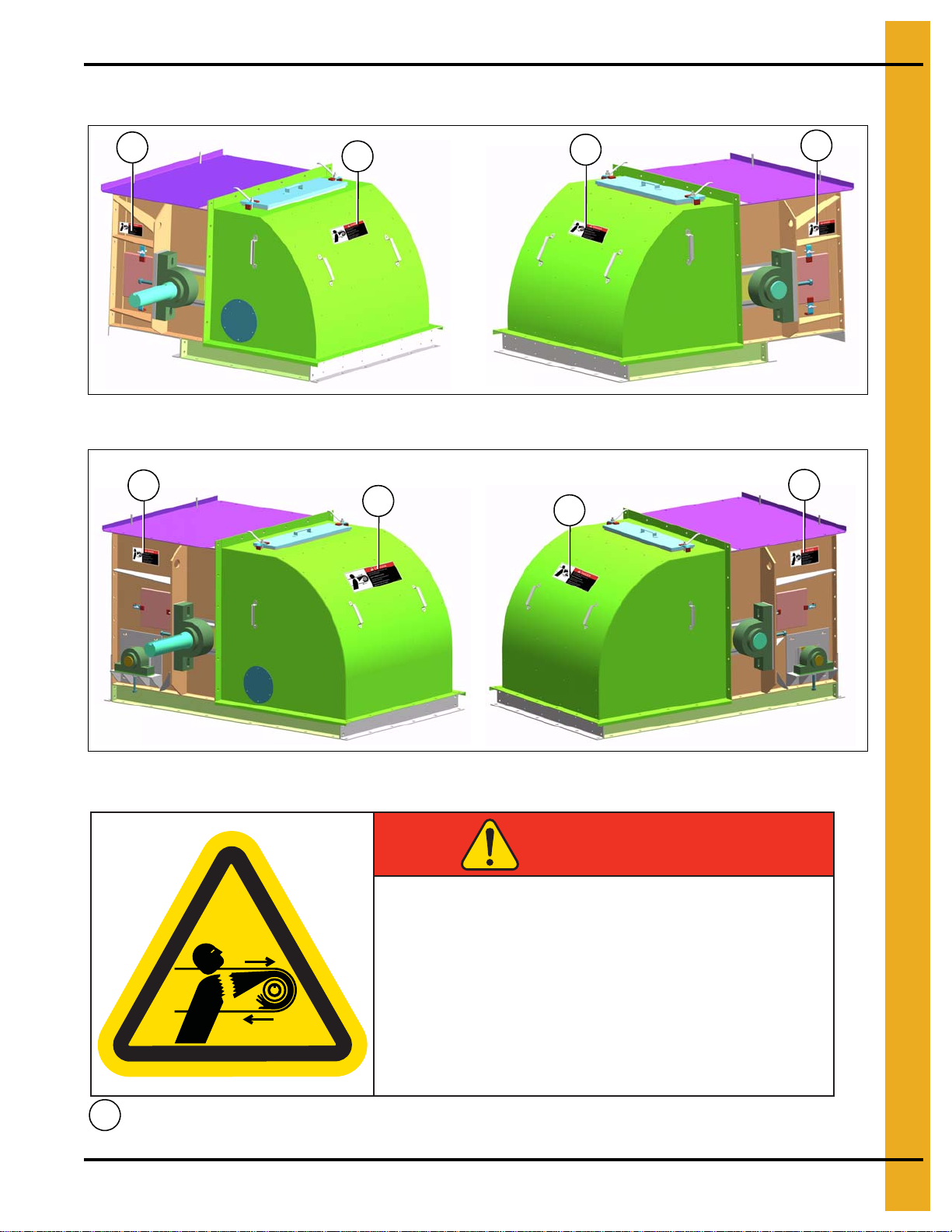
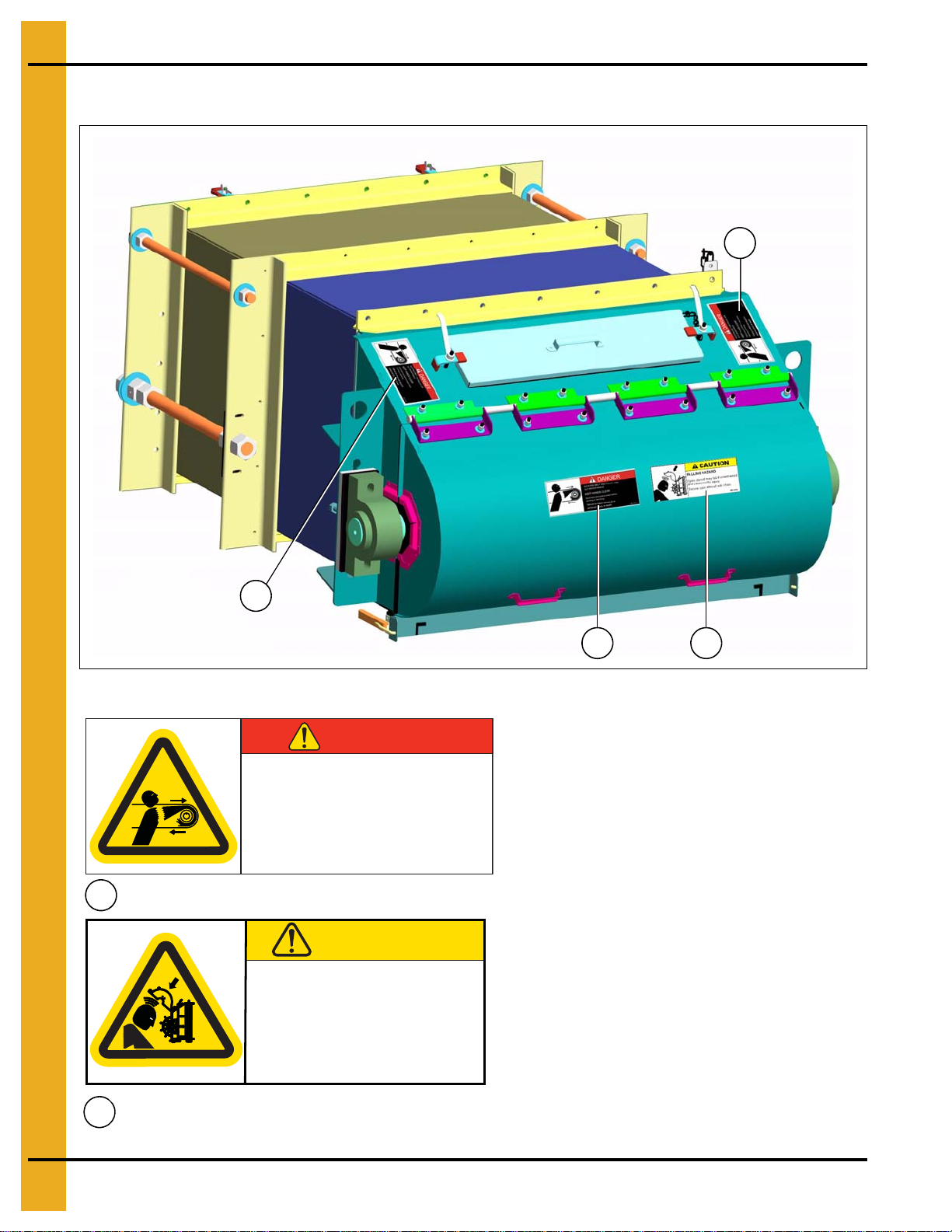
Chapter 3 Decals ....................................................................................................................................................9
Head Section Decal Locations .............................................................................................................. 9
Tail Section Decal Locations ............................................................................................................... 10
Loader Section Decal Locations ......................................................................................................... 11
Intermediate Section Decal Locations ................................................................................................. 12
Belt Guard Cover ................................................................................................................................ 13
Chapter 4 Conveyor Assembly ...........................................................................................................................14
Conveyor Assembly Overview ............................................................................................................ 14
Intermediate Section Installation ......................................................................................................... 15
Cover Installation ................................................................................................................................ 18
Loader Installation ............................................................................................................................... 20
Chapter 5 Motor Assembly .................................................................................................................................22
Motor and Shaft Torque Arm II Installation ......................................................................................... 22
Motor and Torque Arm II Reducer Installation .................................................................................... 24
Chapter 6 Belting Assembly ...............................................................................................................................29
Finding Belt Centerline ........................................................................................................................ 29
Squaring the Belt End ......................................................................................................................... 30
Check the Squareness of the Belt Cut ................................................................................................ 31
Installation of Belt ................................................................................................................................ 32
Splicing the Belt .................................................................................................................................. 33
Belt Tension ........................................................................................................................................ 37
Belt Tracking ....................................................................................................................................... 38
Chapter 7 Loading ...............................................................................................................................................41
Spouting .............................................................................................................................................. 41
Spouting Location ............................................................................................................................... 42
Belt Conveyor Loading ........................................................................................................................ 43
Chapter 8 Options ................................................................................................................................................44
Motion Sensor Option (Whirligig - WG1-4B) ....................................................................................... 44
Pressure Plug Switch Option .............................................................................................................. 45
Chapter 9 Start-Up ...............................................................................................................................................46
Starting Conveyor ............................................................................................................................... 46
Secure Shroud During Maintenance ................................................................................................... 46
Chapter 10 Care and Maintenance .....................................................................................................................47
Bearings ............................................................................................................................................ 47
Welding .............................................................................................................................................. 47
Motor ................................................................................................................................................. 47
Support .............................................................................................................................................. 47
Storage .............................................................................................................................................. 48
Chapter 11 Troubleshooting ...............................................................................................................................49
Chapter 12 Appendix 1 - Reference Information ...............................................................................................50
Chapter 13 Warranty ............................................................................................................................................51

4PNEG-1204 Enclosed Belt Conveyor
1. Introduction
READ THIS MANUAL carefully to learn how to properly use and install equipment. Failure to do so could
result in personal injury or equipment damage.
INSPECT the shipment immediately upon arrival. The customer is responsible for ensuring that all
quantities are correct. The customer should report and note any damage or shortage on the bill of
lading to justify their claim to the transport company.
THIS MANUAL SHOULD BE CONSIDERED a permanent part of your equipment and should be easily
accessible when needed.
This warranty provides you the assurance that the company will back its products when defects appear
within the warranty period. In some circumstances, the company also provides field improvements, often
without charge to the customer, even if the product is out of warranty. Should the equipment be abused
or modified to change its performance beyond the factory specifications, the warranty will become void
and field improvements may be denied.

PNEG-1204 Enclosed Belt Conveyor 5
2. Safety
Safety Guidelines
This manual contains information that is important for you, the owner/operator, to know and understand.
This information relates to protecting personal safety and preventing equipment problems. It is the
responsibility of the owner/operator to inform anyone operating or working in the area of this equipment
of these safety guidelines. To help you recognize this information, we use the symbols that are defined
below. Please read the manual and pay attention to these sections. Failure to read this manual and its
safety instructions is a misuse of the equipment and may lead to serious injury or death.
DANGER
WARNING
CAUTION
NOTICE
This is the safety alert symbol. It is used to alert you
to potential personal injury hazards. Obey all safety
messages that follow this symbol to avoid possible
injury or death.
WARNING indicates a hazardous situation which, if not
avoided, could result in death or serious injury.
CAUTION, used with the safety alert symbol, indicates a
hazardous situation which, if not avoided, could result in
minor or moderate injury.
NOTICE is used to address practices not related to
personal injury.
DANGER indicates a hazardous situation which, if not
avoided, will result in death or serious injury.

2. Safety
6PNEG-1204 Enclosed Belt Conveyor
Safety Instructions
Our foremost concern is your safety and the safety of others associated with this equipment. We want to
keep you as a customer. This manual is to help you understand safe operating procedures and some
problems that may be encountered by the operator and other personnel.
As owner and/or operator, it is your responsibility to know what requirements, hazards, and precautions
exist, and to inform all personnel associated with the equipment or in the area. Safety precautions may be
required from the personnel. Avoid any alterations tothe equipment. Such alterations may produce a very
dangerous situation where SERIOUS INJURY or DEATH may occur.
This equipment shall be installed in accordance with the current installation codes and applicable
regulations, which should be carefully followed in all cases. Authorities having jurisdiction should be
consulted before installations are made.
Follow Safety Instructions
Carefully read all safety messages in this manual and
safety signs on your machine. Keep signs in good
condition. Replace missing or damaged safety signs. Be
sure new equipment components and repair parts include
the current safety signs. Replacement safety signs are
available from the manufacturer.
Learn how to operate the machine and how to use controls
properly. Do not let anyone operate without instruction.
Keep your machinery in proper working condition.
Unauthorized modifications to the machine may impair
the function and/or safety and affect machine life.
If you do not understand any part of this manual or need
assistance, contact your dealer.
Read and Understand Manual
Stay Clear of Rotating Idler
Entanglement in rotating idlers can cause serious
injury or death.
Keep all shields and covers in place at all times.
Wear close fitting clothing. Stop and lock out power
source before making adjustments, cleaning, or
maintaining equipment. Entanglement Hazard

2. Safety
PNEG-1204 Enclosed Belt Conveyor 7
Operate Motor Properly
In an emergency, shut down the power source.
Turn OFF and lock out all power sources before performing
any maintenance.
Do not operate electric motor equipped units until motors are
properly grounded.
Disconnect power on electrical driven units before resetting
motor overloads.
Do not repetitively stop and start the drive in order to free a
plugged condition. Jogging the drive in this manner can damage
the equipment and/or drive components. Electric Shock Hazard
Practice Safe Maintenance
Understand service procedures before doing work. Keep area
clean and dry.
Never lubricate, service, or adjust machine while it is in operation.
Keep hands, feet, and clothing away from rotating parts.
Keep all parts in good condition and properly installed. Fix
damage immediately. Replace worn or broken parts. Remove any
built-up grease, oil, and debris. Maintain Equipment
and Work Area
Remove Paint Before Welding or Heating
Avoid potentially toxic fumes and dust.
Hazardous fumes can be generated when paint is heated by
welding, soldering, or using a torch.
Do all work outside or in a well-ventilated area.
Dispose of paint and solvent properly.
Remove paint before welding or heating:
• If you sand or grind paint, avoid breathing the dust. Wear
an approved respirator.
• If you use solvent or paint stripper, remove stripper with
soap and water before welding. Remove solvent or
stripper containers and other flammable material from
area. Allow fumes to disperse at least 15 minutes
before welding or heating.
Breathing Hazard

2. Safety
8PNEG-1204 Enclosed Belt Conveyor
Prepare for Emergencies
Be prepared if fire starts.
Keep a first aid kit and fire extinguisher handy.
Keep emergency numbers for doctors, ambulance service,
hospital, and fire department near your telephone. Keep Emergency Equipment
Quickly Accessible
Wear Protective Clothing
Wear close-fitting clothing and safety equipment appropriate
to the job.
Remove all jewelry.
Tie long hair up and back.
Wear safety glasses at all times to protect eyes from debris.
Wear gloves to protect your hands from sharp edges on
plastic or steel parts.
Wear steel-toed boots to help protect your feet from falling
debris. Tuck in any loose or dangling shoestrings.
A respirator may be needed to prevent breathing potentially
toxic fumes and dust.
Wear a hard hat to help protect your head.
Wear appropriate fall protection equipment when working at
elevations greater than six feet (6').
Eye Protection
Gloves
Steel-Toed Boots
Respirator
Hard Hat
Fall Protection

PNEG-1204 Enclosed Belt Conveyor 9
3. Decals
Head Section Decal Locations
Figure 3A Standard Head Section
Figure 3B Snub Head Section
111
1
111
1
Disconnect and lockout power before
adjusting or servicing.
ROTATING BELT AND PULLEY WILL
CUT OR ENTANGLE.
Failure to heed will result in
personal injury or death.
KEEP HANDS CLEAR
DC-1672
DANGERDANGER
GSI Group 217-226-4421
1
DC-1672

3. Decals
10 PNEG-1204 Enclosed Belt Conveyor
Tail Section Decal Locations
Figure 3C Belt Conveyor Tail Section
1
21
1
Disconnect and lockout power before
adjusting or servicing.
ROTATING BELT AND PULLEY WILL
CUT OR ENTANGLE.
Failure to heed will result in
personal injury or death.
KEEP HANDS CLEAR
DC-1672
DANGERDANGER
GSI Group 217-226-4421
DC-1690
Secure open shroud with chain.
Open shroud may fall if unrestrained
and cause bodily injury
.
CAUTION
.
FALLING HAZARD
GSI Group 217-226-4421
1
DC-1672
DC-1690
2

3. Decals
PNEG-1204 Enclosed Belt Conveyor 11
Loader Section Decal Locations
Figure 3D Fixed Skirt Loader
Figure 3E Swing-Up Skirt Loader
3
3
Decal on right side in
same location as
decal on left side.
3
3
3
3
Decal on right side in
same location as
decal on left side.
KEEP HANDS CLEAR
Disconnect and lockout power before
adjusting or servicing.
MOVING BELT CAN CUT OR ENTANGLE.
Failure to heed can result in
personal injury or death.
WARNING
DC-1671GSI Group 217-226-4421
3
DC-1671

3. Decals
12 PNEG-1204 Enclosed Belt Conveyor
Intermediate Section Decal Locations
Figure 3F Intermediate Inspection Section
Figure 3G Standard Intermediate Section
Decal on right side in same
location as decal on left side.
13
Decal on right side in same
location as decal on left side.
3
KEEP HANDS CLEAR
Disconnect and lockout power before
adjusting or servicing.
MOVING BELT CAN CUT OR ENTANGLE.
Failure to heed can result in
personal injury or death.
WARNING
DC-1671GSI Group 217-226-4421
Disconnect and lockout power before
adjusting or servicing.
ROTATING BELT AND PULLEY WILL
CUT OR ENTANGLE.
Failure to heed will result in
personal injury or death.
KEEP HANDS CLEAR
DC-1672
DANGERDANGER
GSI Group 217-226-4421
1
DC-1672
3
DC-1671

3. Decals
PNEG-1204 Enclosed Belt Conveyor 13
Belt Guard Cover
Figure 3H Belt Guard Cover
4
5
SHEAR POINT
Keep hands clear of moving
parts. Do not operate with
guard removed. Disconnect
and lockout power before
servicing.
DC-994
SHEAR POINT
Keep hands clear of moving
parts. Do not operate with
guard removed. Disconnect
and lockout power before
servicing.
DC-995
WARNING
4
DC-994
DC-995
5

14 PNEG-1204 Enclosed Belt Conveyor
4. Conveyor Assembly
Conveyor Assembly Overview
1. Remove any banding and crating material. Arrange all the conveyor components in such a fashion
that all are easily accessible.
2. Locate sturdy items to serve as blocking (i.e. wood blocks, saw horses, etc.). Blocking is used to
support the conveyor sections above the ground to help in assembly. Locate and place the conveyor
sections on the blocking in order, starting with the head section and concluding with the tail section.
3. A clearance of at least the width of the conveyor is recommended on all sides of the unit. Less
clearance may be acceptable however, serious consideration must be given to methods of
maintenance, removal and replacement of the conveyor and/or its parts.
4. Thestandardconveyorisconstructedwithone discharge locatedat the driveend.Iftripperdischarge
sections are to be used, the location(s) must be determined before continuing with the conveyor
assembly.Itmaybe necessarytopositionashorter intermediatesection toserveas aspacerin order
to accommodate the placement of the tripper discharge(s) where required.
5. Always consult with the approval prints for exact conveyor layout. Maintain adequate clearance for
tail extension.
6. During installation of the conveyor, string a chalk line along the conveyor sides to assure that the
conveyor is being assembled in a straight line. All hardware should be included with your conveyor.
It is recommended that all flanges be caulked to seal the conveyor to keep the dust in and the
weather out.
7. After all sections are caulked and bolted, the loader(s) is/are ready to be installed. Loaders must be
installed with the grain stream moving in the same direction and same speed as the conveyor belt.
(See Page 41 for recommended spout loading.)
8. After location of the loader(s) (as to spouts, gates and valves) has been established, the
loader(s) are bolted to the conveyor. Do not weld loader(s) to the conveyor. (See Page 20 for
loader installation.)
9. Belt may now be hand fed through the conveyor. Make sure when splicing belt that each cut is clean,
square and straight. Detailed belt assembly instructions are listed on Pages 29-40. These
instructions should be followed closely and read thoroughly before starting this step.
10. Check drive belts for tension. Also check the oil level in the speed reducer. Reducers are shipped
without oil. Refer to Page 50 for the type and quantity of oil. (DO NOT overfill reducer.)

4. Conveyor Assembly
PNEG-1204 Enclosed Belt Conveyor 15
Intermediate Section Installation
NOTE: Make sure to read assembly overview on Page 14.
1. Intermediate sections are supplied in standard ten feet (10') lengths. Depending on your application
and individual specifications however, shorter sections may be required to accommodate a desired
overall length.
2. After making sure the flanges are aligned, tighten all hardware on the trough section. (It is
recommended that the flanges are caulked to ensure sealing from dust and outside moisture.)
3. During assembly of the intermediate sections, carefully inspect each flange joint to ensure that
the inside bottom and side surfaces of the intermediates are flush. A chalk line is helpful during
this phase of the assembly to ensure the proper alignment of the intermediate section surfaces.
The maximum run-out in any direction should be ±1/4". Make sure the conveyor is level in
horizontal applications.
4. Proceed by attaching the head and tail assemblies using the same alignment procedures and
precautions noted in the preceding paragraph.
NOTE: It is critical for straitness of the conveyor that the sides and bottom flanges are aligned flush.
Also, it is important that the inside dimensions of the box measure equidistant from side-to-side
both top and bottom of the intermediate section (Dimension A = Dimension B). (See Figure 4A.)
Figure 4A End View of Intermediate Section (Liners not shown for clarity.)

4. Conveyor Assembly
16 PNEG-1204 Enclosed Belt Conveyor
Intermediate Section Installation (Continued)
1. Intermediate sections bolt together along the side and bottom flanges. The covers are fastened to
the cover channels by flat clips and easy grip handles. (See Figure 4B.)
Figure 4B
2. Standard intermediate sections do not have a direction in which they bolt to other intermediate
sections. The cover channels connect intermediate sections on both ends.
3. Two (2) inspection intermediate sections are included on each installation. They should be
assembled at the head and tail. The inspection holes should be oriented closest to the head or
tail. (See Figure 4C.)
Figure 4C
ADC
D
B
B
Ref # Description Ref # Description
ACover CCover Channel
B Flat Clips D Easy Grip Handles
F
E
G
Ref # Description
ETail Section
F Intermediate Inspection Section
GInspection Door

4. Conveyor Assembly
PNEG-1204 Enclosed Belt Conveyor 17
Intermediate Section Installation (Continued)
4. The inspection door end of each intermediate section has adapter angles with slotted holes for
bolting to head or tail sections. (See Figure 4D.)
Figure 4D
5. A special cover channel is provided with the tail as shown in Figure 4E.
Figure 4E
Ref # Description
HAdapter Angle with Slotted Holes
Ref # Description
ITail Cover Channel
H
I

4. Conveyor Assembly
18 PNEG-1204 Enclosed Belt Conveyor
Cover Installation
1. Fasten covers to the belt conveyor with the 3/8" easy grip handles provided. Adequately tighten the
3/8" handles so that the covers are in tight contact with conveyor cross channels. (See Figure 4F.)
Figure 4F
2. When a loader is on the conveyor, thecover section may have to be cut accordingly toaccommodate
the loader. (See Figure 4G.) For installation of a loader, see loader installation on Page 20.
Figure 4G
Ref # Description
A3/8" Wing nut on tail section to secure cover
Ref # Description
BEasy Grip Handles
A
B
B

4. Conveyor Assembly
PNEG-1204 Enclosed Belt Conveyor 19
Cover Installation (Continued)
3. Conveyor covers are made to fit over the entire width and half the length of a conveyor intermediate
section. Standard covers measure approximately 4'-7" in length. When a loader is ordered, the cover
may be measured and cut to take up the displacement of the loader housing. This depends on the
position of the loader. (See Figure 4H.)
Figure 4H Standard Cover Length
NOTE: DO NOT walk on conveyor covers.
4'-7"

4. Conveyor Assembly
20 PNEG-1204 Enclosed Belt Conveyor
Loader Installation
Fixed Skirt Loader
1. The fixed skirt loader always attaches at the tail end so no cover modifications should be necessary.
The soft rubber skirts are adjustable and can be set to lightly touch the conveyor belt.(See Figure 4I.)
Figure 4I Fixed Skirt Loader
Figure 4J
NOTE: GSI’s recommendation for loader installation includes a minimum distance of no less than 6"
between the center of loader inlet and the tail assembly. (See Figure 4J.)
Table of contents
Other GSI Group Accessories manuals
Popular Accessories manuals by other brands

Silvercrest
Silvercrest SPBS 5000 B2 operating instructions

Scan Cool
Scan Cool SD 226 BE user manual

GOAL ZERO
GOAL ZERO YETI 500X LITHIUM user guide

Heath Zenith
Heath Zenith 6168 owner's manual

Silvercrest
Silvercrest HG01100-BS Operation and safety notes

Resolution
Resolution CryptiX NanoMax RE622 Series user manual