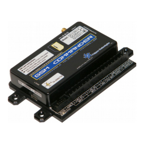
GSM Commander GC0108 User manual

User Manual for GC0108, GC0328, GC0648,
GC1288
Applicable to software package Version 8.00 and up
Revision: V8.00 Last Edited 11 May 2023
Before Attempting to connect or operate this product, please read these instructions in its entirety
This manual is intended to provide detailed technical specifications and explanations, to the basic
user as well as the more technically-minded person. This manual is a live document, and will be
updated often with new information. Please ensure that you have the latest version, by checking our
website at: http://www.gsmcommander.com.
Changelog:
CDH May 2023 – Initial release of V8

TABLE OF CONTENTS
Features 3
Specifications 4
System requirements 4
Dimensions 5
Installation 6
Environment 6
Power Supply 6
USB Port 6
SIM Card 6
Antenna 7
Software Installation 7
Mounting 7
Optically - Isolated Digital Inputs 8
Outputs 9
Temperature Sensor 10
Analog Input 11
Battery Input 12
Expansion Unit 13
Dimensions of Expansion Unit 18
Status LEDs 18
Testing the GSM Commander 20
Configuration Via PC 21
Configuration via SMS 24
Set Administrator number 24
Clear Administrator number 24
Check Administrator number 25
Check Airtime 25
Add a Number to the list 25
Remove a Number from the list 25
Enable/Disable statements 25
Override GPRS Settings 26
Reset GPRS 26
Reset GSM Commander 26
IF-THEN Behaviour statements 27
Supported IF Conditions 27
Supported THEN Actions 32
Multiple Actions to a Single IF Condition 35
Message Parameters 35
Variables 36
Timed operations 37
Firmware Updates 37
4-20MA Analog Application Note 38
Application Examples 39
Troubleshooting 42
Guarantee 44
Important Notice / Disclaimer 44
Manufacturer Contact Details 45
© Polygon Technologies. All rights reserved Page 2

1. FEATURES
* Only able to view the current status of the unit via Airdrive.
© Polygon Technologies. All rights reserved Page 3

2. SPECIFICATIONS
Weight
200gram
Dimensions
146,2 x 85,2 x 27mm
Power Supply
11-30V DC via DC Jack
Power Consumption
~ 5-10W
Current Consumption
~ 150mA at idle (no inputs or outputs active)
Operating Temperature
-10°C to +60°C
Storage Temperature
-20°C to +80°C
Digital Inputs
Opto-isolated. Inputs draw 2 - 45mA, depending on
voltage. Can accept any DC signals of any type,
including:
Dry Contacts
Open Collector (NPN)
Closed Collector (PNP)
DC Voltage (5-24V)
Digital Outputs
2 x SPDT Relay Contact rating: 8Amp DC (10 - 48V) or
4amp AC (110 – 400V). Expandable to maximum of 32*
Analog Inputs
1 x Analog input 8bit resolution 0-10V/4-20mA *
(Not available on GC0108)
IO Connector type
Rising clamp terminals
2G Frequency bands
GSM/GPRS/EDGE 900/1800 MHz
4G Frequency bands
LTE-FDD B1/B3/B5/B7/B8/B20
*Model Dependent (See Feature Matrix in Section 2 )
3. SYSTEM REQUIREMENTS
The setup software requires a PC with the following specifications:
Operating system
WinXP / Vista / Win7 / Win8 /Win10 / Win11
Computer Architecture
Pentium 2 or higher IBM compatible PC
Disk space
2MB
Ports
1 x free USB port
© Polygon Technologies. All rights reserved Page 4

4. DIMENSIONS
© Polygon Technologies. All rights reserved Page 5

5. INSTALLATION
5.1. Environment
Due to the make-up of the GSM Commander and its electronics, we STRONGLY advise that it not be installed in
close proximity to a variable speed drive or any other electrically noisy equipment. DO NOT install the GSM
Commander into a metal enclosure unless an antenna is mounted on the outside of the enclosure.
5.2. Power Supply
The GSM Commander has a 2.1mm DC jack connector where a power supply must be connected. The power
supply should have the following specifications:
Output Voltage: 11v-30v
Output Current: 0.5A
Polarity:
A suitable power supply is supplied with the retail product.
In industrial applications, it is advised that the GSM Commander be installed into its own metal housing
and be powered from a separate power supply with a DC Filter. (As opposed to sharing one with other
equipment).
Please Note: While the GSM Commander has fairly rugged internal power supply circuitry, no special provision
for lightning protection is made. If the GSM Commander is used in an area that is prone to thunderstorms, it is
advisable to use a commercially available lightning suppressor (The same applies to inputs or outputs that are
connected to wires longer than 2 or 3 meters). The guarantee does not cover damage resulting from lightning
strikes! The GSM Commander can operate reliably from voltages in the range of 11 to 30V DC.
5.3. USB Port
The GSM Commander provides a USB port that connects to a PC using the supplied USB cable. This allows the
PC to configure the unit.
5.4. SIM Card
The GSM Commander accepts a standard GSM SIM card from any network. The SIM card may be prepaid or on
contract. If the SIM Card is purchased as part of a prepaid plan, ensure that the card is loaded with sufficient
airtime.
WARNING: DO NOT Insert or remove the SIM card while the GSM Commander is powered!!
Note that airtime will decrease with every SMS that is sent from the unit. The unit can automatically detect if
the airtime is running low. It is the user's responsibility to make sure that the airtime is topped up. See your
network's documentation on how to purchase and load airtime.
The SIM card is fitted into the back of the unit, as indicated by the legend on the enclosure. The SIM card will
click into place and is removed simply by pressing against it. The card will pop out with a “click” sound, ready
to be completely removed.
Before you install your SIM Card:
Install the SIM card into a normal cellular phone
Verify that there is no SIM PIN enabled (The phone must not ask for a PIN when switched on with this SIM
card inside) If the phone does request a PIN, you need to enter the correct pin so that the phone can
start, and then disable the SIM Card PIN. See your cellphone documentation on how this can be done.
Verify that you are able to send an SMS message.
The SIM card will now work with the GSM Commander.
Please Note: If you are using a prepaid SIM card, be aware that if the SIM card has not produced a billable
event on the network for a long period of time (typically 3 months), the card will be deactivated by the
network, and the SIM card then becomes useless. It is strongly recommended that you configure the GSM
Commander to send you an SMS every now and then (once or twice a week) so that your SIM card remains
active on the network.
The GSM Commander can ONLY check the airtime of a PREPAID SIM card.
© Polygon Technologies. All rights reserved Page 6

5.5. Antenna
The GSM Commander is supplied with a basic antenna operating in the GSM and LTE frequency
bands. Screw the antenna to its connector on the unit (only finger-tight). Verify using a cellphone,
that there is sufficient signal at the proposed installation site. On a phone with a 4 or 5-bar signal
strength indicator, you should have at least 1-2 bars of signal.
If the signal is too weak, the GSM Commander may have trouble sending or receiving SMS messages.
In these cases, try and find a better location, or order one of our special antennas.
Contact Polygon Technologies with your request for a special antenna.
5.6. Software Installation
The latest software is available to download from our website for free at:
https://gsmcommander.com/downloads/software/
Simply download the correct version of software for your model of GSM Commander & execute the
installer and follow instructions.
5.7. Mounting
The GSM Commander is housed in a very durable ABS casing which has 4 protruding tabs, which
allows it to be mounted firmly to any surface by means of a screw. There is also a DINrail mounting
kit available separately.
Please note: The GSM Commander is not water or weatherproof. The GSM Commander must be
mounted indoors, or inside an appropriate IP65-rated weatherproof enclosure. The guarantee does
not cover damage resulting from water ingress! DO NOT mount the GSM Commander inside a steel
cabinet, unless you also mount a separate antenna on the outside of the cabinet.
Suitable antennas can be ordered from Polygon Technologies.
© Polygon Technologies. All rights reserved Page 7

5.8. Optically - Isolated Digital Inputs
The GSM Commander itself provides 2 signal inputs. The number of inputs can be expanded by the
addition of Expansion modules, up to a maximum of 32 inputs (depending on type). Each of these
inputs have 4 terminals associated with them:
+– Internal positive supply (14V)
+IN – Positive input
–IN – Negative input
–– Internal negative supply (Zero volts)
To connect a switch or contact to an input, simply connect the switch between the + and +IN
terminals, and a wire between the – and –IN terminals. The reverse is just as suitable, i.e. that you
connect a wire between + and +IN and place the switch between – and –IN.
You may need an input to activate when power is supplied from some other unit. A good example will
be a burglar alarm that applies power to the wires going to the siren. In such a case, it will be a
simple matter of connecting the positive wire to the +IN input, and the negative wire to the –IN input.
© Polygon Technologies. All rights reserved Page 8

Please keep in mind that these inputs are designed for operation from 5v to 24v. If you require to
connect a voltage above 25V and below 40V to these terminals, you should connect a 1K resistor in
series with the input, as shown below.
The +and –terminals are internally connected to the input power supply of the GSM Commander via
a fuse and a diode. These terminals are provided to make it easy to connect dry contacts to the
GSM Commander.
If the power supply is 14V, the voltage at the +and –terminals will be slightly less at about 13.8V
(due to an internal series diode for reverse polarity protection).
One should not attempt to draw more than 50-100mA in total from the power terminals at the inputs
on the GSM Commander. For each expansion unit, the same applies.
© Polygon Technologies. All rights reserved Page 9

5.9. Outputs
The GSM Commander itself provides 2 x 8A (DC) Relay outputs. The number of outputs can be
expanded by the addition of Expansion modules, up to a maximum of 32 outputs (depending on
type). Each of these inputs each have 3 terminals associated with them:.
Each of these inputs each have 3 terminals associated with them:
COM – Common Terminal
N/C – Normally Closed Terminal
N/O – Normally Open Terminal
When the output is off, the COM and N/C terminals will be internally connected to each other.
When the output is on, the COM and N/O terminals will be internally connected to each other.
Note that there are small LED indicators next to the output terminals, that will show if the output is
ON or OFF. (If the LED is on, then the output is also on) In the picture below, the output is
connected so that the lamp will light up when the output is on.
This output can be used to control devices and appliances, and is rated for 8A DC. It may be used to
control most types of electrical loads, excluding AC motors above 500W.
Here are some examples of things you CAN directly switch on and off using the outputs on the GSM
Commander:
Gate motors and any other motor less than 500W
Mains Lights (energy savers, incandescents, halogens) (maximum 750W)
Here are some examples of things that you can NOT directly switch on and off using the outputs on
the GSM Commander:
Ovens, Heaters, kettles
Pumps and motors above 500W
Please note: Keep in mind that if required, the above loads can easily be switched on and off using
an externally connected relay or contactor.
© Polygon Technologies. All rights reserved Page 10

5.10. Temperature Sensor
One can connect 2 temperature sensors to the GSM Commander (at the expansion port via a
temperature interface module) to measure temperature and allow the GSM commander to perform
certain tasks if the temperature falls above or below a certain point. The sensor provides an
accuracy of 2°C.
There are two temperature sensor options:
Low Temp: Measures from -17 to +26°C
High Temp: Measures from 0 to 60°C
(You need to select the correct version in the setting page of SmartSetup)
A Modbus temperature expansion module is available which allows for an additional 4 temperature
inputs on the GC061and the GC1281 per expansion, max 4 per device (16 x temperature readings).
5.11. Analog Input
The GSM Commander provides a single 0-10,8V analog input, which can be used to measure incoming
voltages from sensor devices. Using an appropriate resistor, one can also connect 4-20mA sources to
the GSM Commander. (See application note under section 18)
What makes this input so special, is that the GSM Commander
can interpret the analog value on your behalf. It is perhaps
the best to explain this at the hand of a good example.
Suppose you have a water tank, with a level sensor that is
connected to the analog input of the GSM Commander. The
sensor is such, that when the tank is empty, the voltage is
1.2V, and when the tank is full, the voltage is 7.8V. The
configuration software allows you to request the current
reading in a scaled format. You would thus tell the software
that 7.8V should correspond to 5000 litres, and 1.2V should
correspond to 0 litres, and leave the rest of the calculations
to the GSM Commander.
You can now receive a message from the Commander, detailing the actual contents of the tank in
litres, instead of just a raw value. (Which you would otherwise have had to convert back to “real”
numbers yourself).
Please note that this feature assumes a linear relationship between the input voltage and the
desired output units. Thus, this will not work very well for a cylindrical tank that is mounted on its
side, as the voltage from the level sensor is not linearly proportional to the actual contents of the
tank.
The user is also able to define the message to precede, and the message to follow the analog value.
© Polygon Technologies. All rights reserved Page 11

The output of the circuit above feeds to an Analog-to-Digital converter with a reference voltage of
0.98V, and a resolution of 8 bits. The full-scale input voltage to the GSM Commander is therefore
10.8V. The range of the analog input can easily be increased by the addition of a resistor in series
with the analog input.
Below are some examples of resistor values, and the resultant input ranges.
1K Ohm : 0 – 11.8V
3.3K Ohm : 0 - 14.0V
6.8K Ohm : 0 – 17.4V
10K Ohm : 0 – 20.6V
15K Ohm : 0 – 25.5V
Smartsetup Software assumes no series input resistor, when defining behaviour statements for the
analog input.
The software shows both a voltage and a “counts” value when selecting trip points for the analog
input. The “counts” value is a variable from zero to 255 (8 bits). If you have connected a 3.3K Ohm
resistor in series, and you want to select a trip point at, say 12V, you will ignore the voltage shown
by the configuration software, and simply select the correct counts value of 214. ((12 / 14) x 250*)
*Please note: The input is NOT isolated, and must be used with care.
5.12. Battery Input
The GSM Commander provides connections for an external rechargeable 12V battery. Under normal
circumstances, the GSM Commander will trickle-charge the battery at a current of about 75mA. In
the case of a power failure, the GSM Commander then starts drawing power from the battery to
continue operating. It is important to note that should your battery drop below 10.8Vdc during a
sustained power outage, the GSM Commander will unlikely be able to charge the battery up again
In the case of a power failure, the GSM Commander can continue operating from the external
battery. The unit can be configured to perform certain tasks (like sending a warning SMS) if the
battery voltage falls below a certain point, and can also perform tasks in the case of a power
failure. (Like sending an SMS and switching on emergency lighting)
© Polygon Technologies. All rights reserved Page 12

In cases where the GSM Commander is used in conjunction with a large system with its own battery
(such as UPS systems), the battery terminals of the GSM Commander can be safely connected to the
large (12V) battery, and the GSM Commander can then monitor the battery voltage for you (only
while power is NOT supplied to the power input connector).
Also, in cases where the user may want to connect other hardware directly to the battery, be aware
that this will probably drain the battery, since the charging current from the GSM Commander is so
low. Other hardware should rather be connected to the power terminals provided at the inputs.
(See section 5.8 for more information on this).
VERY IMPORTANT:
The GSM Commander performs no voltage or current regulation when charging the battery. Internal
to the GSM Commander, the Battery terminal is wired with a 20ohm resistor between the + Batt
terminal and the positive power supplied to the GSM Commander. It is therefore important to
understand that you CAN NOT power the GSM Commander from 24v and use a 12v backup battery,
because the GSM Commander will over charge the battery. Ideally you want the GSM Commander to
be powered from a voltage that is about 2v higher than the battery voltage, to allow safe charging.
There is a diode in parallel with this resistor (cathode facing to the battery) to allow the GSM
Commander to draw power from the battery under power-fail conditions. A resettable fuse provides
added protection against voltage spikes and short circuits.
5.13. Modbus Expansion Unit
The GSM Commander supports comprehensive expansion by means of the GSM Commander Modbus
Expansion unit, which provides an additional 5 inputs and 5 outputs similar to the ones found on the
GSM Commander itself. A total of 6 Expansion units may be daisy chained to provide a maximum of
30 outputs and 30 inputs (Depending on the model) in addition to those on the GSM Commander.
Upon bootup, the GSM Commander will poll all valid Modbus addresses and identify the modules that
are found. Thereafter the GSM Commander will regularly communicate to each unit in the bus. The
“Modbus Status” LED on each Modbus expansion unit will flash each time it receives communication
from the GSM Commander. Note that many different kinds of modbus device can be connected to
the Modbus port.
© Polygon Technologies. All rights reserved Page 13

Connection
The Expansion unit can be connected either via the modbus screw terminal (shown in orange), or via
the 10way ribbon cable (labelled IN and OUT). Typically the ribbon cable used when the expansion
unit is installed next to the GSM Commander. If you have more than one expansion unit, you can
daisy chain them using ribbon cables connected to the IN and OUT terminals as shown, or you can
just connect them in parallel using the screw terminals as shown. If you connect via the screw
terminals (and you use the correct type of cable), the expansion unit can be placed far away, even
as far as 50m.
The Expansion unit can get its power either via the ribbon cable or via the small modbus screw
terminals. If the GSM Commander has a battery connected, battery power will automatically be
used to power the expansions (via either the ribbon or the screw terminals) when needed.
Generally, if more than 2 expansions are connected, it is recommended to do this via the modbus
screw terminals, because the ribbon cable is limited in the amount of current it can handle for
powering the expansion units
IMPORTANT: The GSM Commander must be connected to the IN terminal of the first expansion unit,
and the OUT terminal of the first expansion unit is connected to the IN terminal of the second
expansion unit.
Connecting Multiple Expansion units
© Polygon Technologies. All rights reserved Page 14

Expansion Connection (continued)
You are also able to use a combination of ribbon cable and screw terminal connections. This is ideal
if you are planning to have one expansion unit next to the GSM Commander and another installed
remotely.
© Polygon Technologies. All rights reserved Page 15

Connecting using Modbus screw terminals
It is recommended to use a shielded, 4 core twisted pair cable. The longer your cable run, the
higher the quality cable you need.
It is critical that you use a twisted pair for the data pins. The nature of the wires being twisted
together is what provides the bulk of the noise immunity we need to achieve long distances. We are
less concerned with how the power lines are running. If your cable happens to have more than 2
pairs, we would recommend to use both wires in a pair for each of the power lines.
If your cable has a screen, it is recommended to connect it to the GND terminal on the one end
ONLY.
DIP setting
The DIP setting on each expansion unit will determine where in the IO space of the GSM Commander,
the expanded inputs and outputs will be mapped. The switches are labelled 1,2,3,4 on the switch
itself, and 1,2,4,8 shown on the PCB. Please ignore the 1,2,3,4 on the switch.
This is used to set the Modbus Address. The first Modbus address is 0 (zero), which will have all 4
switches in the OFF position, as shown below. In this case, this expansion unit’s 5 inputs and 5
outputs will be mapped to input and outputs 3-7 respectively in the GSM Commander. (Input and
output 1,2 are on the GSM Commander itself.)
© Polygon Technologies. All rights reserved Page 16

DIP Settings (continued)
Here is a legend to show how other expansions in the chain should be set up (the maximum number
of inputs and outputs supported, is model dependant)
Expansion Unit Power
Each Expansion unit has both a 12V DC jack and battery input, so that it could also be powered by a
separate power supply and battery. Applying power to the Expansion unit either through the DC jack
or battery terminal is optional. The Expansion unit can draw power via the ribbon cable, but under
certain conditions it is better to supply a separate 12V source and battery to the expansion unit.
These conditions are:
When the ribbon cable run becomes very long (>5m)
If you are going to connect more than one expansion unit
If you expect to draw power from the input on the Expansion unit
If you expect most of the inputs and outputs on the expansion to likely be active at once
The Expansion unit will automatically detect if power is applied at either of the it's 12V inputs (DC jack
and battery) and thus stop drawing power via the ribbon cable. So to ensure that the Expansion unit
functions properly in mains power failure conditions, it is advised that you connect a 12V battery to it's
battery terminals together with it's main 12V power supply.
© Polygon Technologies. All rights reserved Page 17

Interface Ribbon cable
Supplied with each Expansion unit is a short (10cm) ribbon cable for interface purposes, but this
ribbon can also be longer, up to 1m.
The ribbon cable connectors are mounted such that pin 1 on the one end connects to pin 10 on the
other, Pin 2 connects to pin 9 etc.
5.14. Dimensions of Expansion Unit
5.15. Status LEDs
The GSM Commander has 2 LEDs to show the current status of the GSM Commander. The red LED,
labeled “GSM”, shows the status of the internal GSM cellular engine, while the green LED, labeled
“STATUS”, shows the status of the GSM Commander as a whole. These two LEDs can paint a
remarkably intricate picture about the state of your installation. We provide the legend to interpret
these LEDs as a separate page so that you can print it out and perhaps leave it inside your cabinet
for handy reference..
© Polygon Technologies. All rights reserved Page 18

© Polygon Technologies. All rights reserved Page 19

5.16. Testing the GSM Commander
5.16.1. Status Request
The GSM Commander (even with a blank configuration) has a built-in test feature. If the GSM
Commander receives “TEST GSMC” as an SMS message, it will reply to the number that sent the
message, with the following text:
DT=01/01/2013-12:00:00 < Indicates current date & time of the GSM Commander
Sig=68% < Indicates the received signal strength
Airt=35 < Indicates the amount of airtime remaining
FW=8.99 < Indicates the firmware version
SN=120648-30225 < Indicates the serial number
PWR=On < Indicates status of mains power
Batt=13.2V < Indicates voltage of battery (if connected)
Ana=108 < Indicates analog value in counts (0 - 250)
tA=23 < Indicates temperature of Probe A (in °C) if connected
tB=44 < Indicates temperature of Probe B (in °C) if connected
IN1,2=0,1 < Indicates status of inputs 1 and 2 (0 = active, 1 = inactive)
OUT1,2=0,1 < Indicates status of outputs1 and 2 (0 = active, 1 = inactive)
Please Note: The airtime remaining will be displayed as “Airt=???” if airtime checking has been
disabled or the incorrect network operator has been chosen in the current setup.
© Polygon Technologies. All rights reserved Page 20
This manual suits for next models
3
Table of contents
Other GSM Commander Controllers manuals