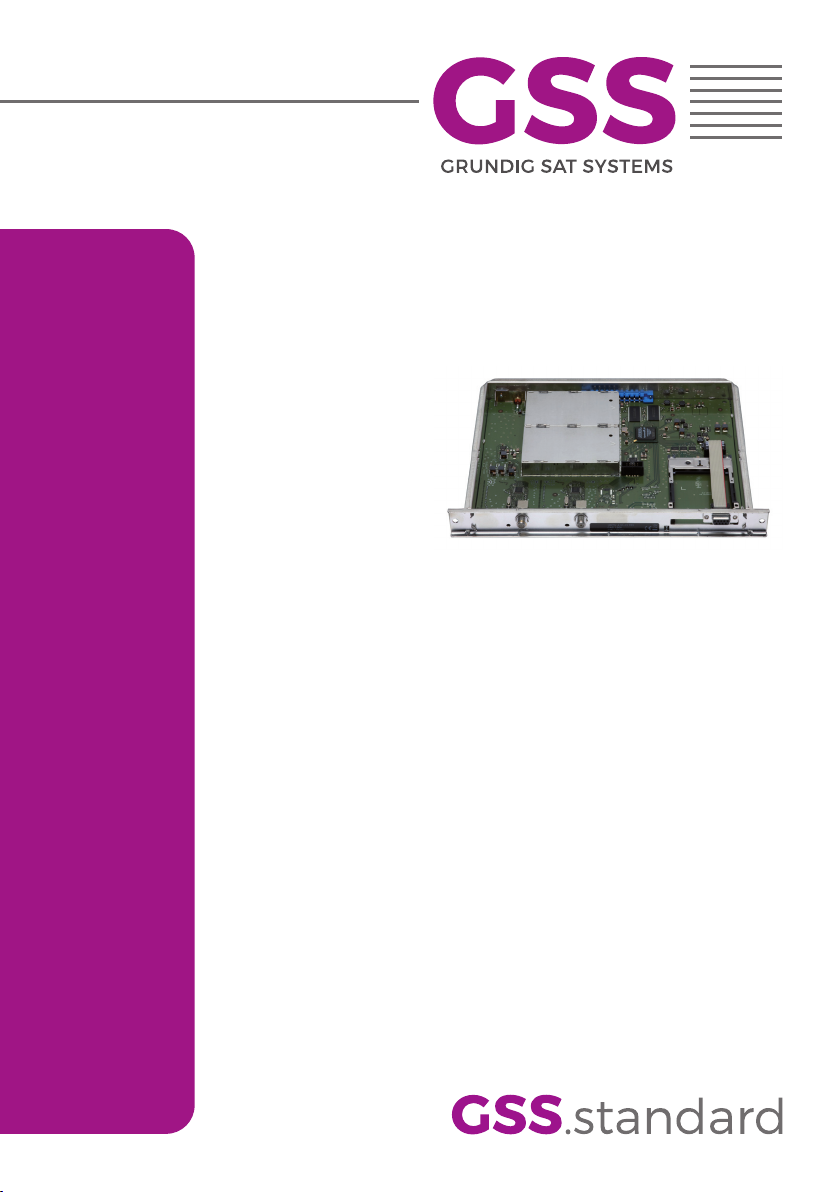
GSS.standard HDTV 1200 C CI User manual

Assembly Instruction
HDTV 1200 C CI

- 2 - HDTV 1200 C CI
Contents
1 Safety regulations and notes ........................................................................4
2 General information ....................................................................................5
2.1 Packing contents ............................................................................5
2.2 Meaning of the symbols used ..........................................................5
2.3 Technical data ...............................................................................5
2.4 Description ...................................................................................6
2.5 Software query..............................................................................7
2.6 How the TPS module works .............................................................7
Station selection ............................................................................7
Changing the Transport stream and ORGNET-ID................................7
Changing the NIT ..........................................................................8
Changing the SID ..........................................................................8
3 Assembly ....................................................................................................8
3.1 Installing the cassette......................................................................8
3.2 EMC regulations ............................................................................9
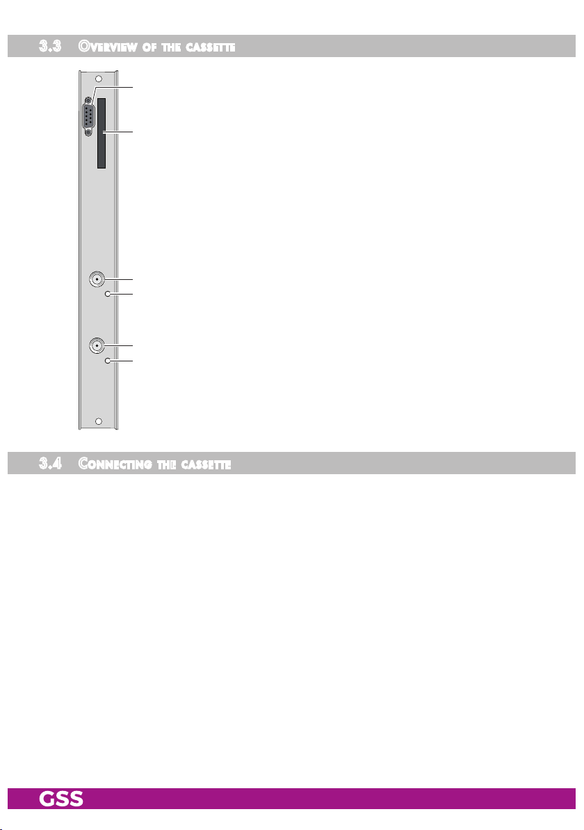
3.3 Overview of the cassette ..............................................................10
3.4 Connecting the cassette ................................................................10
3.5 Retrofitting a CA module ..............................................................11
4 The control panel at a glance .....................................................................12
4.1 Menu items .................................................................................12
4.2 Control panel ..............................................................................12
5 Programming ............................................................................................13
5.1 Preparation .................................................................................13
5.2 Notes on programming via the control software .............................13
5.3
Notes on level setting ...................................................................13
5.3 Programming procedure ...............................................................14
5.4 Programming the cassette ............................................................16
Selecting the cassette ...................................................................16
Output signal (Level, Modulator) ....................................................17
Output parameter (QAM modulation, Inverting the user signal) .........18
Output Symbol Rate .....................................................................19
Output channel / Output frequency ...............................................20
Input parameters .........................................................................21
LNB oscillator frequency ..........................................................21
Input symbol rate ....................................................................22
DVB mode .............................................................................22
Setting the input frequency .......................................................23

- 3 - HDTV 1200 C CI
Station selection .....................................................................24
Descrambling Stations .............................................................24
Service ID (SID) ......................................................................24
Operation with a CA module ........................................................27
PID monitoring .......................................................................27
CA module ............................................................................27
Output data rate ..........................................................................28
Transport stream ID and the ORGNET-ID.........................................29
Network Information Table (NIT) ....................................................30
NIT version ............................................................................31
Factory reset ...............................................................................32
Saving settings ............................................................................32
5.6 Programming via the control software ............................................33
Quick setup via configuration file ..................................................33
Creating/exporting a configuration file .....................................33
Importing a configuration file ...................................................35
Service-ID (SID) ...........................................................................36
6 Final procedures ........................................................................................38
7 Channel and frequency tables ....................................................................39

- 4 - HDTV 1200 C CI
1 safety regulations and notes
• Assembly, installation and servicing should be carried out by authorised
electricians.
• Switch off the operating voltage of the system before beginning with assem-
bly or service work or pull out the mains plug.
• Do not perform installation and service work during thunderstorms.
• Install the system so it will not be able to vibrate…
- in a dust-free, dry environment
- in such a manner that it is protected from moisture, fumes, splashing wa-
ter and dampness
- somewhere protected from direct sunlight
- not within the immediate vicinity of heat sources
- in an ambient temperature of 0 °C to +50 °C. In case of the formation of
condensation wait until the system is completely dried.
• Ensure that the head-end station is adequately ventilated. Do not cover the
ventilation slots.
• Beware of short circuits
• No liability is accepted for any damage caused by faulty connections or
inappropriate handling.
• Observe the relevant standards, regulations and guidelines on the installa-
tion and operation of antenna systems.
• The standards IEC/EN/DIN EN 50083 resp. IEC/EN/DIN EN 60728 must
be observed.
• For further information please read the assembly instructions for the head-
end station used.
• Test the software versions of the head-end station and the cassette and
update them if necessary. The current software versions can be found at
"www.mygss.eu".
Take action to prevent static discharge when working on the device!
Electronic devices should never be disposed of in the household rubbish. In
accordance with directive 2002/96/EC of the European Parliament and the
European Council from January 27, 2003 which addresses old electronic and
electrical devices, such devices must be disposed of at a designated collection
facility. At the end of its service life, please take your device to one of these
public collection facilities for proper disposal.

- 5 - HDTV 1200 C CI
2 general information
2.1 PaCking Contents
1 Cassette HDTV 1200 C CI 2 RF cables
1 Brief assembly instructions
2.2 meaning of the symbols used
Important note
—> General note
• Performing works
2.3 teChniCal data
The devices meet the following EU directives:
2011/65/EU, 2014/30/EU, 2014/35/EU
The product fulfils the guidelines and standards for CE labelling (page 40).
Unless otherwise noted all values are specified as "typical".
RF input
Frequency range: ....................................................... 925 … 2150 MHz
Level range: ............................................................ 60 dBμV … 80 dBμV
Return loss: ..................................................................................> 8 dB
DVB-S modes: ............................................ QPSK 1/2 , 2/3 , 3/4 , 5/6 , 7/8
DVB-S2 modes: ...................QPSK 1/2 , 3/5 , 2/3 , 3/4 , 4/5 , 5/6 , 8/9 , 9/10
8PSK 3/5 , 2/3 , 3/4 , 5/6 , 8/9 , 9/10
Symbol rate DVB-S: .......................................... QPSK: 2 … 45 MSymb/s
Symbol rate DVB-S2: ........................................ QPSK: 10 … 30 MSymb/s
8PSK: 10 … 31 MSymb/s
RF output
Frequency range: ............................................. 42.0 MHz … 860.0 MHz
Channels: ............................................................................ S21 … C69
Types of modulation: ..................................QAM 4, 16, 32, 64, 128, 256
Output level: ............................................................................. 96 dBμV
Output impedance: .........................................................................75 Ω

- 6 - HDTV 1200 C CI
Connections
SAT inputs: .............................................................................2 F sockets
RF output: ...........................................................................1 IEC socket
Connection strip (10-pin): ..................for supply voltages and control circuits
RS-232 socket: ..................................... serial interface for software update
Common Interface: ...........................several channels can be descrambled.
Remote maintenance
Remotely controllable (via PSW 1000*): ..............................................yes
Remote update (via BEflash*): .............................................................yes
(* and a corresponding management unit)
2.4 desCriPtion
The cassette converts services (programmes) modulated in DVB-S-/DVB-S2
standard
into one outgoing QAM modulated signal for feeding into a cable
network
.
The
cassette
has two SAT inputs and one RF output. It is equipped with
two input channel strips ("
A
" and "
B
")
TPS
Tuner A
Tuner B
CA Modul
Modulator HF Output
The channel strips are indicated in the head-end station display with "Bx …A"
and "Bx …B". Using one adequate CA module scrambled stations of two trans-
ponders can be descrambled
. The control of the cassette takes place via the
control unit of the head-end station.
Two LEDs provide an indication of the SAT IF input signal quality based on
their colour (only when stations are selected). Additionally the quality of the
transport stream received is displayed ("CN…"). The integrated TPS module
(Transport Stream Processing) processes the data of the transport streams.
The QAM modulated RF output signals are sent through the RF output of the
cassette to the output collector. The common output level of the channel strips
can be set at the output collector.
Software update for the operating software of the cassette is possible via satellite.
When the head-end station is switched on, the two-line LC display shows the
software version of the control unit. To operate this cassette the software version

- 7 - HDTV 1200 C CI
of the control unit must be "V 45" or higher. You can find the current operating
software for the control unit, the software "BE-Flash" and the current assembly
instructions on the website "www.mygss.eu".
The cassette is intended for use in the
STANDARD LINE
head-end stations.
2.5 soft ware query
Control unit
If necessary, you can activate the indication of the software version of the
control unit manually:
• Press any two keys on the control unit of the head-end station simultaneously
until the display goes dark and the software version, e.g. "V 45" appears.
Cassette
The software version of the cassette, e.g. "V 45", is shown in the display after
activating the cassette (see page 16).
2.6 how the tPs module works
After decoding QPSK or 8PSK -modulated signals, the demodulated data
streams can be accessed via the integrated TPS module. These data streams,
also called transport streams, contain several stations in all their components
(video, audio, data and service information), which can be changed using the
TPS module.
station seleCtion
Individual stations can be selected. This reduces the data rate and, conse-
quently, the output symbol rate. Additionally stations of the different transport
streams can be assembled to a new transport stream.
Changing the transPort stream and orgnet-id
The transport stream ID can be changed. If the stations of two transponders are
combined into one transport streams a new identification must be allocated to
realise the channel search of the settop boxes connected without mistakes.
If the ORGNET-ID is changed a new NIT must be generated.

- 8 - HDTV 1200 C CI
Changing the nit
The transport stream contains data in the form of tables which the receiv-
ers evaluate and require for convenient use. The TPS module can adjust the
"Network Information Table" (NIT) to accommodate the new station data. The
"NIT" contains data which is required by the set-top boxes connected to the
cable network for the automatic search feature.
Changing the sid
By default the SIDs are set automatically. When required the SID can be set
manually using the control software
PSW 1000 (from version 43 on).
3 assembly
3.1 installing the Casset te
– Ensure the head-end station is mounted so it will not be able to vibrate.
Avoid, for example, mounting the head-end station onto a lift shaft or any
other wall or floor construction that vibrates in a similar way.
– Before installing or changing a cassette unplug the power cable from the
mains power socket.
• Remove the fastening screws 1 of an unoccupied slot from the bracket of
the head-end station.
• Insert the cassette in this slot and push it into the housing.
• Align the cassette and apply slight pressure to connect it to the connections
of the board and the RF bus bar.
• Fasten the cassette with the screws 1.
1
1

- 9 - HDTV 1200 C CI
3.2 emC regulations
To comply with the current EMC regulations, it is necessary to connect the lines
leading in and out of the head-end station using cable terminals.
When mounting the cassette in a head-end station which is installed in a 19"
cabinet, make sure the connections leading in and out for the 19" cabinet are
made using cable terminals.
CLASS
KLASSE
The attenuation of shielding of the connection lines for antenna must meet the
requirements for "Class A".
• Insert the required number of cable terminals in the openings provided in
the head-end station or in the 19
"
cabinet.
Tighten the nuts of the cable terminals until the teeth on the lock washers
put under
have penetrated the exterior coating and a good connection is made between the
housing
/ 19" cabinet
and cable terminals.

- 10 - HDTV 1200 C CI
3.3 overview of the Casset te
2
3
5
6
4
11 D-SUB socket "RS 232"
2 Slot for CA module
3
SAT input
"
A
" (channel strip "
A
"
4
Status LED of input "
A
"
5
SAT input
"
B
" (channel strip "
B
")
6
Status LED of input "
B
"
The operating software of the cassette can be updated via the
9-Pin D-SUB socket "RS-232" using a PC or notebook and the
software "BE-Flash". You can find the current operating soft-
ware on the website "www.mygss.eu".
3.4 ConneCting the Casset te
• Connect the RF connections to the inputs
3 (channel strip "
A
") and 5
(channel strip "
B
") .

- 11 - HDTV 1200 C CI
3.5 retrofitting a Ca module
The cassette is equipped with a common interface for CA modules of various
scrambling systems and service providers. Scrambled stations can only be
descrambled with a CA module suitable for the scrambling system and the
corresponding smart card. The smart card contains all the information for
authorisation, descrambling and subscription.
Caution
– Check with the distributor or manufacturer of the CA module to be used
to ensure that it is suitable for descrambling several channels.
– The hardware and software of this cassette have been thoroughly prepared
and tested.
– Any changes made by programme provider to the structures in the pro-
gramme data might impair or even prevent this function.
– When working with the CA module, please read the corresponding operat-
ing manual from the respective provider.
• Insert the smart card
into the CA module
so that the chip
3 on the smart
card
1 faces the thicker side (top) of the CA module
2.
• Insert the CA module into the slot
4 with the top side of the CA module
facing the left side of the cassette.
• Push the CA module without canting into the guide rails of the CA slot 4
and contact it to the common interface.
34 12

- 12 - HDTV 1200 C CI
4 the Control Panel at a glanCe
4.1 menu items
Programme the
cassette
using the buttons on the control unit of the head-end
station. The two-line display of the control unit then shows the menus.
The parameters and functions to be set are underlined.
Use the key to select the following main menu items:
– Output signal
– QAM settings
– Output channel / output frequency
– Tuner
– Station selection
– CA module
– Output data rate
– Transport stream and ORGNET-ID
– Network Information Table (NIT)
– Factory reset
4.2 Control Panel
The key pad on the head-end station is used to scroll through the menus step-by-step:
scrolls forward through the menus.
select parameters in the menus.
set values, initiate actions.
selects sub-menus.
scrolls backward through the menus.
saves all entries.
BE-Remote V 45
please wait . . .

- 13 - HDTV 1200 C CI
5 Programming
5.1 PreParation
• Test the software versions of the head-end station and the cassette and up-
date them if necessary. The current software versions can be found on the
website
"
www.mygss.eu
"
.
• Connect the test receiver to the RF output or the test output of the head-end
station.
• Set the output channel / output frequency of the
cassette
(page 20) and adjust
the TV test receiver to this channel / frequency.
•
Switch on the modulator if necessary (
page
17).
5.2 notes on Programming via the Control soft ware
It is much more convenient to programme the cassette via the control software
PSW 1000.
—> Therefore please read the operating instructions for the software
PSW 1000
, you will find at "www.mygss.eu". If you do not have
internet access, we will send you a DVD on request.
A quick setup of the cassette and filter settings as well as remapping a service
ID (SID) is only possible via
PSW 1000 (from version 43 on).
—> Therefore observe chapter 5.6, page 33
5.3
notes on level setting
In order to prevent interference within the head-end station and the cable sys-
tem, the output level of the cassette must be decreased by 10dB compared to
analogue cassettes at 64 QAM, and by 4 dB compared to analogue cassettes
at 256 QAM.
• Measure the output levels of the other cassettes and tune them to a uniform
output level using the appropriate level controls or software dependent on
the head-end station used.
—> Please regard the assembly instructions of the respective head-end
station.

- 14 - HDTV 1200 C CI
5.3 Programming ProCedure
Bx 4
on -3 dB
OUTPUT
=>
Bx 4
C68
OUTPUT
850.00 MHz
B
BE–Remote
please wait …
V 45
Box 4
V 6
DVBS2-CIM
– – –
Box 1
..............
..............
..............
Bx 1A
C5-12,S3-24
TWIN-SAT
C07
Böx 4
C5-12,S3-24
TWIN-SAT
C07
Box 5
..............
..............
..............
+
t > 10 s
A
▶
◀/
01/06Bx 4A/B TV* –
Das Erste
auto / 0x0001…0xFFFF
▶
◀/
▶
◀/
Bx 4
31667
DATARATE
(25772)
Bx 4
0x0001,0100
TS/ONID
off
Bx 4
off
NIT
=> Make
on / off
Ein / On
▶
◀/
off / on
M
B
A
▶
Bx 4
Defaults
FACTORY
=>
Bx 4
STORE
FACTORY
=> M
auf Werkseinstellung
zurücksetzen und speichern
reset to factory defaults
and store
Tuner A /
Tuner B /
Bx 4A/B
11836 -1.8
FREQ
CN 12
Bx 4A/B
27500 DVB-S
SYMBOL ▶
◀/
▶
◀/
Bx 4A/B
10600 MHz
LNB
▶
▶
▶
Bx 4
Tuner A OK
INPUT
=>
DVB-S / QPSK… /
8PSK… / DTV…
▶
◀/
+ / - / X
▶
◀/
10600 / 9750
27500 / 22000
01/06
auto
Bx 4A/B TV* –
0x6DCA =>
*) Die angezeigte Information ist
abhängig vom verwendeten
CA-Modul.
The information displayed is
dependent on the CA module
used.
Bx 4 01/03
Information *)
MENU
Bx 4
PID Check
CA
on =>
on / off
M
▶
◀/
on / off
+5 … -10 dB
Bx 4A/B
256-QAM
QAM-MODE
normal
▶
◀/
▶
◀/
4 … 256
normal / inverse
Bx 4A/B
6900
QAM-RATE
1000 … 7500
Bedienhinweise
"blättert" Menüs vorwärts.
"blättert" Menüs rückwärts.
wählen die Eingabeposition
wählt Untermenü
stellen Werte ein,.
speichert alle Eingaben.
1 zeigt die Eingabeposition
Operating Hints
scrolls forward through the menu.
scrolls backward through the menu.
select the enter position.
selects a submenu.
set values and triggers actions.
saves all entries.
1 shows the enter position
▶ Make
0…31
Bx 4
Version
NIT
––
◀
Page 15

- 15 - HDTV 1200 C CI
Bx 4
on -3 dB
OUTPUT
=>
Bx 4
C68
OUTPUT
850.00 MHz
B
BE–Remote
please wait …
V 45
Box 4
V 6
DVBS2-CIM
– – –
Box 1
..............
..............
..............
Bx 1A
C5-12,S3-24
TWIN-SAT
C07
Böx 4
C5-12,S3-24
TWIN-SAT
C07
Box 5
..............
..............
..............
+
t > 10 s
A
▶
◀/
01/06Bx 4A/B TV* –
Das Erste
auto / 0x0001…0xFFFF
▶
◀/
▶
◀/
Bx 4
31667
DATARATE
(25772)
Bx 4
0x0001,0100
TS/ONID
off
Bx 4
off
NIT
=> Make
on / off
Ein / On
▶
◀/
off / on
M
B
A
▶
Bx 4
Defaults
FACTORY
=>
Bx 4
STORE
FACTORY
=> M
auf Werkseinstellung
zurücksetzen und speichern
reset to factory defaults
and store
Tuner A /
Tuner B /
Bx 4A/B
11836 -1.8
FREQ
CN 12
Bx 4A/B
27500 DVB-S
SYMBOL ▶
◀/
▶
◀/
Bx 4A/B
10600 MHz
LNB
▶
▶
▶
Bx 4
Tuner A OK
INPUT
=>
DVB-S / QPSK… /
8PSK… / DTV…
▶
◀/
+ / - / X
▶
◀/
10600 / 9750
27500 / 22000
01/06
auto
Bx 4A/B TV* –
0x6DCA =>
*) Die angezeigte Information ist
abhängig vom verwendeten
CA-Modul.
The information displayed is
dependent on the CA module
used.
Bx 4 01/03
Information *)
MENU
Bx 4
PID Check
CA
on =>
on / off
M
▶
◀/
on / off
+5 … -10 dB
Bx 4A/B
256-QAM
QAM-MODE
normal
▶
◀/
▶
◀/
4 … 256
normal / inverse
Bx 4A/B
6900
QAM-RATE
1000 … 7500
Bedienhinweise
"blättert" Menüs vorwärts.
"blättert" Menüs rückwärts.
wählen die Eingabeposition
wählt Untermenü
stellen Werte ein,.
speichert alle Eingaben.
1 zeigt die Eingabeposition
Operating Hints
scrolls forward through the menu.
scrolls backward through the menu.
select the enter position.
selects a submenu.
set values and triggers actions.
saves all entries.
1 shows the enter position
▶ Make
0…31
Bx 4
Version
NIT
––
◀
Page 14

- 16 - HDTV 1200 C CI
5.4 Progra mming the Casset te
—> Pressing the button for longer than 2 seconds cancels the
programming procedure. This takes you back to the programme
item "Selecting the cassette" from any menu. Any entries that have
not been saved are reset to the previous settings.
—> Entries in the menus can be saved by pressing the key. You are
taken back to the "Selecting the cassette" menu item.
—> Pressing the button returns to the previous menu.
• Switch on the head-end station
—> The display shows the software version (e.g. V 45)
—> The processor reads the
cassettes
‘ data (approx. 10 seconds).
BE–Remote
please wait …
V 45
t > 10 s
Ein / On
seleCting the Cassette
Box 4
V 6
DVBS2-CIM
– – –
Box 1
..............
..............
..............
Bx 1A
C5-12,S3-24
TWIN-SAT
C07
Böx 4
C5-12,S3-24
TWIN-SAT
C07
Box 5
..............
..............
..............
+
• Select the
cassette
you want to programme (e.g. Box 4) by repeatedly press-
ing the button if necessary.
—> The display shows e.g. the menu
"Box 4 DVBS2-CIM"
:
"Box 4" stands for
slot
4
"DVBS2-CIM" Type of cassette
"V 6" Software version of the cassette

- 17 - HDTV 1200 C CI
• Press the button.
—> The "Ouput signal" – "OUTPUT" menu is activated.
outPut signal (level, modulator)
In this menu you
– set the output level of the cassette,
– switch the modulator on or off and
– can activate the submenus for the output parameters.
Bx 4
on -3 dB
OUTPUT
=>
Set the output level
This menu item is used to set the output level of the modulator.
• By pressi
ng adjust the output level ("0
" … "
–10 dB").
—> To adjust the output level to the output levels of the other cassettes
please pay attention to chapter 6 "Final procedures"
Switching the modulator off or on
• To switch off the modulator place the cursor under "on" using the
button
and switch "off" the modulator using the buttons.
—>
The switched off modulator is indicated by " - - - " in the display
instead of the channel or frequency display.
• In the case the modulator is switched "off" use the to switch it "on".
Set the output parameter
In this submenu you can set the output parameter of the QAM-Signal.
—> To skip the setting of the output parameters press the but-
ton. The "Output channel / Output frequency" – "OUTPUT" main
menu is activated (page 20).

- 18 - HDTV 1200 C CI
• Press the
button to activate the submenus for the output parameters.
—
> The "Output parameter"
– "QAM-MODE" submenu is activated.
outPut Par ameter (qam modul ation, inverting the user signal)
In this menu, you can set the QAM modulation and invert the user signal.
Bx 4A/B
256-QAM
QAM
normal
QAM modulation
•
Use to set the QAM modulation ("4" … "256").
—> For higher QAM modulation, the output symbol rate is decreased.
An output QAM modulation of >64QAM places a large burden
on the cable network. Due to noise, delay and frequency response
problems, reception of the converted output signal can be affected.
Inverting the user signal
For exceptional cases and "older" digital cable receivers, the spectral position
of the user signal can be inverted
"inverse"
. The factory default is "normal".
• Use to place the cursor under "normal".
• Use to set the spectral position to "inverse".
• Press the button.
—> The "Symbol rate" – "QAM-RATE" submenu is activated.

- 19 - HDTV 1200 C CI
outPut symbol rate
In this menu, you can set the output symbol rate.
Bx 4A/B
6900
QAM-RATE
•
Use the buttons to place the cursor under the number to be changed
("Number 1") and set the symbol rate with the buttons . The value
set corresponds to the new output symbol rate.
—> Please also refer to the menu "Output data rate" – "DATARATE"
(Seite 28).
• Press the button.
—> You will be returned to the "Output signal"
– "OUTPUT" main menu
(page 17).
• Press the button.
—>
The "Output channel / Output frequency" – "OUTPUT" main menu is
activated.

- 20 - HDTV 1200 C CI
outPut Channel / outPut frequenCy
In this menu, you can select the channel or frequen cy setting for the adjustment
of the RF output. The channel setting covers the range of channels S21 …
C69, the frequency setting covers the range from 42.0 MHz to 860.0 MHz.
—> The QAM signal is normally transmitted with a bandwidth of 8 MHz.
This means that you can only use the channel centre frequency of
the existing channel grid in the range of channels S21 … C69
(frequency grid 8 MHz). The CCIR channel grid is 7 MHz in the
range of the lower frequency bands (channels C2 … S20). There-
fore the frequency setting is used here. If one uses the existing chan-
nel grid of 7 MHz in these channel ranges, this will result in inter-
ference (overlapping) with the 8 MHz QAM signal packages, thus
causing transmission problems.
For programming in these channel ranges and in the frequency
ranges below them, we recommend starting with channel S21 /
306 MHz going back in steps of 8 MHz (see frequency table on
page 39), or reducing the bandwidth of the QAM output signal by
removing stations.
Bx 4
C68
OUTPUT
850.00 MHz
Setting the output frequency
• Use the
buttons to place the cursor under the digit to be set for the
frequency display then use to set the output frequency wished.
—>
The corresponding channel is displayed.
Setting the output channel
• Use the
buttons to place the cursor under the channel display then
use to set the output channel wished.
—>
The corresponding frequency is displayed.
• Press the button.
—>
The "Input parameters" – "INPUT" main menu is activated.
Table of contents