– 3 –
© LEYBOLD VAKUUM GMBH GA05.212/10 - 09/00
TABLE OF CONTENTS
4.3 Electrical connection.............................................................19
4.3.1 Connecting the relay contacts (also refer to Fig. 8) ........19
4.3.2 Connecting the test sockets ...........................................20
4.4 Operating modes/remote control ..........................................21
4.5 Operator control ....................................................................21
5 SETTING THE EQUIPMENT CONFIGURATION ......... 22
5.1 Selecting the supply voltage range .......................................22
5.2 Withdrawing the PC boards...................................................23
5.2.1 NT10 ...............................................................................23
5.2.2 NT12 ...............................................................................23
5.2.3 NT13 ...............................................................................23
5.3 Locations of the plug-in and jumpers ...................................24
5.4 Relay statuses .....................................................................25
5.5 Setting the configuration of relay K1 ....................................26
5.6 Setting the configuration of relay K2 ....................................26
5.7 Setting the resonance monitoring funct. ..............................27
5.8 Jumper field S2 ....................................................................27
5.9 Measuring the motor frequency ...........................................28
5.10Connecting examples for remote control .............................29
EC DECLARATION OF MANUFACTURE ......................... 32
EC DECLARATION OF CONFORMITY ............................ 33
FACTORY CERTIFICATE ................................................ 34
FIGURES
Fig.1 TURBOTRONIK NT10 ............................................................6
Fig.2 TURBOTRONIK NT12 ............................................................6
Fig.3 TURBOTRONIK NT13 ............................................................6
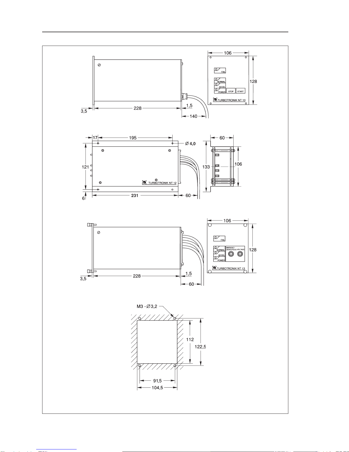
Fig. 4 Dim.drawings of the Turbotronik NT10, NT12, NT13..............8
Fig. 5 Rear panel of the TURBOTRONIK NT10..............................12
Fig. 6 TURBOTRONIK NT 12, pin assignment...............................16
Fig. 7 TURBOTRONIK NT 13, pin assignment...............................20
Fig. 8 Voltage at the front panel test sockets .................................20
Fig. 9 Setting the supply voltage range..........................................22
Fig.10 Supply voltage selector switch TURBOTRONIK NT12 .......22
Fig. 11 Layout Platinen NT10 ........................................................24
Fig. 12 PC board layouts NT12 and NT13.....................................25
Fig. 13 - 17 Setting the configuration of relay K1 ...........................26
Fig. 18 - 22 Setting the configuration of relay K2 ......................26/27
Fig. 23 Setting the resonance monitoring function .........................27
Fig. 23 - 26 Jumper field S2 ......................................................27/28
Fig. 28 Diagram, measuring the motor frequency........................28
Fig. 29 Measuring the motor frequency.........................................28
Fig. 30 - 35 Connecting examples for remote control ..................29
Note (5/3) = refers to figure. The first digit refers to the number
of the figure, the second digit to the position.