GST I-9403 User manual

30308397 Page 1 Issue 1.01
Features
Providing 16 tones.
Using ultra bright LEDs as source for light
indication.
Loop powered and external 24V power supplied.
Power-saving consumption mode and normal
consumption mode (normal consumption mode is
defaulted)
Single/dual address programmable.
Working modes: sounder and strobe, strobe only,
and sounder only.
Standard: EN 54-3.
Description
I-9403 Intelligent Sounder Strobe (the sounder strobe) is
an audible and visual alarm device installed in field,
which can be activated by fire alarm control panel in fire
control center. After activated, it will generate strong
audible and visual alarm signal to warn people in field.
The sounder strobe can use together with a 25.5mm
high shallow base or a 40mm high deep base. Deep
base is used if there is no special statement in this
manual.
Connection & Cabling
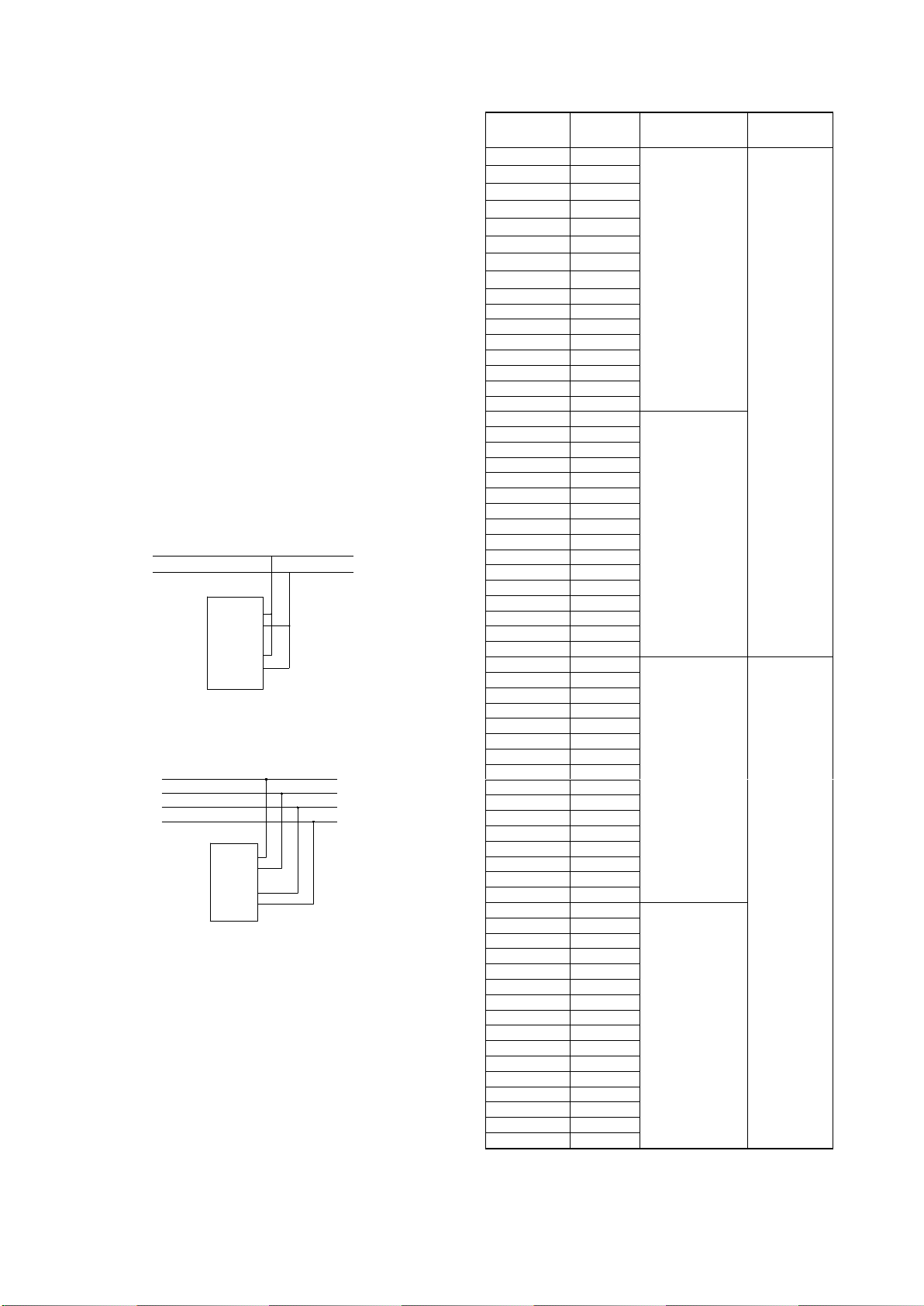
Terminals on the base are shown in Fig. 2.
5mm
55mm
80mm
Tamper-proof knockout
97.5mm
G
1
K
1
D
D
2
1
2
Z
2
K
S
Z
Fig. 1 Fig. 2
Z1(2), Z2(4): Loop of the control panel,
polarity-insensitive.
D1(9), D2(7): To external 24VDC power,
polarity-insensitive.
Recommended Wiring
1.5mm2 or above fire cable for D1, D2, Z1 and Z2,
subject to local codes.
Installation
When surface mounted, the sounder strobe should
be placed 0.2m from the ceiling for normal space height.
When the conduit is embedded, the base should be
mounted on the back box. When conduit is surface
mounted, the deep base should be adopted. Knock the
knockout hole, and connect the conduit with it. The
mounting hole spacing and mounting direction of the
sounder strobe with a deep base are shown in Fig. 2.
Mounting method is shown in Fig. 3a and Fig. 4. The
conduit must be embedded when the shallow base is
used, as shown in Fig. 3b.
Sounder Strobe
Back Box
Knock-off Hole
Conduit
Sounder Strobe
Back Box
Conduit
Fig. 3a Fig. 3b
The base and the sounder strobe are twisted
together. When mounting, remove the sounder strobe,
thread cables through the cable entry in the base and
connect with corresponding terminals, then twist the
sounder strobe onto the base.
Conduit Sounder Strobe
Fig. 4
If the sounder strobe is required to be tamper-proof,
knock down the knockout as shown in Fig. 1 and fix it
with ST2.9×6.5 self-tapping screws (in this case, it can
only be removed by a cross screwdriver).
Application
Address, tone, programming method, working mode,
consumption mode can be set through P-9910B
programmer.
I-9403
Intelligent Sounder Strobe
The Intelligent Solution

30308397 Page 2 Issue 1.01
Tone, single/dual address mode and consumption
mode can be set as the same as programming the
parameter of a module by P-9910B programmer. Refer
to Table 1 for parameters and P-9910B Installation and
Operation Manual for details.
Working mode can be set as same as programming
device type by the programmer, refer to P-9910B
Installation and Operation Manual for details.
Sounder and strobe (defaulted): 24;
Sounder only: 20;
Strobe only: 21.
In single address mode, the sounder strobe will
sound the preset tone with flash frequency 1.4×
(1±20%)Hz when activated.
In dual addresses mode,
The sounder strobe will sound the pre-alarm
tone (refer to Table 1) with flash frequency
0.7×(1±20%)Hz when activating the first address;
The sounder strobe will sound a preset tone
(refer to Table 1) with flash frequency
1.4×(1±20%)Hz when activating the second
address;
The sounder strobe will sound the preset tone
(refer to Table 1) with flash frequency 1.4×
(1±20%)Hz when activating the first and second
address together.
Wiring diagram
Fig.5 shows that the sounder strobe is
loop-powered.
Sounder Strobe
Z1
D2
D1
Z2
Z1
Z2
Fig. 5
Fig. 6 shows that the sounder strobe is
supplied by an external 24V power.
Sounder Strobe
Z1
D2
D1
Z2
Z1
Z2
D1
D2
Fig. 6
An example shows that how to set the sounder
strobe addressed 25 as dual addresses, tone 15 and
normal consumption mode.
Switch on the P-9910 programmer, input the password
and press the Function key and number 3. Enter 63 and
the Program key. The setting is successful when P
appears on the display. The sounder strobe is now to be
programmed Address No. 25 and 26.
Table 1 shows tone mode, programming method,
consumption for the sounder strobe (Single address,
tone 14 and normal consumption are defaulted).
Table 1
Parameter
Tone
Programming
method
Consump-
tion mode
01
01
Single
address
Power-
Saving
02
02
03
03
04
04
05
05
06
06
07
07
08
08
09
09
10
10
11
11
12
12
13
13
14
14
15
15
16
16
17
01
Dual
addresses
18
02
19
03
20
04
21
05
22
06
23
07
24
08
25
09
26
10
27
11
28
12
29
13
30
14
31
15
32
16
33
01
Single
address
Normal
34
02
35
03
36
04
37
05
38
06
39
07
40
08
41
09
42
10
43
11
44
12
45
13
46
14
47
15
48
16
49
01
Dual
addresses
50
02
51
03
52
04
53
05
54
06
55
07
56
08
57
09
58
10
59
11
60
12
61
13
62
14
63
15
64
16

30308397 Page 3 Issue 1.01
Sound Level Data
Distance 1m (unit:dB)
Angle
Horizontal
Vertical
20V
28V
20V
28V
Normal
Mode
Power-saving
Mode
Normal
Mode
Power-saving
Mode
Normal
Mode
Power-saving
Mode
Normal
Mode
Power-saving
Mode
Tone 01
15°
91
81
94
85
90
79
93
85
45°
92
84
95
88
91
80
94
87
75°
93
88
97
92
92
87
96
90
105°
93
89
96
92
92
88
96
90
135°
92
86
95
89
91
81
94
88
165°
90
83
94
85
89
79
93
84
Tone 02
15°
86
81
90
85
86
81
90
85
45°
90
86
93
89
89
85
91
88
75°
95
88
96
92
94
88
9
92
105°
92
88
95
92
92
89
95
93
135°
90
84
92
89
89
84
92
88
165°
88
82
92
86
86
81
92
85
Tone 03
15°
86
80
88
84
85
79
87
84
45°
88
83
91
87
86
80
91
83
75°
92
85
95
89
91
81
95
84
105°
92
85
95
89
91
80
96
85
135°
88
82
90
86
87
80
87
85
165°
85
81
87
84
84
79
86
84
Tone 04
15°
86
81
88
85
86
81
90
85
45°
88
86
92
89
87
85
91
88
75°
94
86
98
89
94
85
97
89
105°
94
86
97
90
93
86
97
89
135°
90
84
95
88
90
84
94
88
165°
89
82
92
86
88
82
91
86
Tone 05
15°
87
81
90
84
86
80
89
83
45°
91
88
93
92
90
80
92
84
75°
93
89
96
94
93
80
95
85
105°
93
89
97
93
93
81
96
86
135°
90
87
93
90
89
81
91
84
165°
87
81
91
84
86
80
90
83
Tone 06
15°
86
79
89
83
85
78
90
82
45°
91
83
93
87
90
84
92
87
75°
93
87
96
91
94
87
96
91
105°
93
88
96
91
93
88
95
90
135°
89
83
92
87
88
83
90
86
165°
85
80
89
83
85
79
89
83
Tone 07
15°
86
76
88
78
85
75
88
77
45°
92
81
95
85
91
81
94
84
75°
92
83
97
87
92
83
96
87
105°
91
83
95
87
91
83
94
86
135°
92
80
96
84
91
79
95
84
165°
86
77
90
82
86
76
90
81
Tone 08
15°
90
80
94
82
89
79
93
81
45°
94
81
97
84
94
81
96
84
75°
96
84
99
87
95
84
98
87
105°
96
84
99
88
96
85
99
88
135°
93
81
97
85
93
81
97
84
165°
89
79
92
82
88
78
91
81

30308397 Page 4 Issue 1.01
Continue
Angle
Horizontal
Vertical
20V
28V
20V
28V
Normal
Mode
Power-saving
Mode
Normal
Mode
Power-saving
Mode
Normal
Mode
Power-saving
Mode
Normal
Mode
Power-saving
Mode
Tone 09
15°
84
81
87
84
83
81
86
84
45°
89
84
93
87
88
82
93
83
75°
92
88
95
92
93
81
96
83
105°
92
88
95
92
92
82
94
83
135°
89
83
93
87
88
82
92
82
165°
85
80
88
83
84
81
89
82
Tone 10
15°
86
80
90
83
85
79
89
82
45°
90
83
94
87
90
83
93
87
75°
94
89
97
93
93
89
96
92
105°
93
89
97
93
92
88
97
93
135°
93
84
95
87
92
84
95
86
165°
86
80
90
83
86
79
91
83
Tone 11
15°
88
78
91
81
88
78
90
80
45°
91
81
93
85
90
81
92
84
75°
93
85
95
89
92
84
95
88
105°
93
86
96
89
92
85
95
89
135°
90
82
94
85
89
81
93
85
165°
88
77
92
81
87
77
91
81
Tone 12
15°
85
81
88
84
84
81
88
83
45°
89
84
92
88
88
84
92
87
75°
92
88
96
91
92
87
95
91
105°
92
87
96
91
92
86
95
91
135°
89
83
93
87
88
83
92
87
165°
85
80
88
83
84
80
88
83
Tone 13
15°
85
78
89
79
84
77
89
79
45°
91
81
93
85
90
81
93
85
75°
94
86
97
90
93
86
97
90
105°
94
86
98
89
93
85
96
89
135°
90
82
95
85
90
81
94
85
165°
87
78
90
81
86
77
91
81
Tone 14
15°
87
80
91
84
86
79
90
84
45°
93
84
96
89
92
83
96
88
75°
96
89
100
91
95
88
99
91
105°
95
88
99
91
95
87
98
90
135°
92
84
95
87
91
84
95
86
165°
88
80
91
83
87
79
91
82
Tone 15
15°
84
78
87
82
83
77
87
81
45°
86
82
89
85
86
78
88
81
75°
90
84
93
89
89
78
92
81
105°
90
85
93
88
90
77
93
82
135°
86
81
89
85
85
78
89
81
165°
84
77
87
81
83
77
87
80
Tone 16
15°
85
83
87
88
84
82
88
87
45°
88
87
93
90
88
86
92
90
75°
91
89
96
94
90
89
95
93
105°
92
89
95
92
91
88
95
92
135°
88
87
91
90
88
87
90
88
165°
85
83
88
87
85
83
87
87

30308397 Page 5 Issue 1.01
Specification
Operating Voltage
Loop: 24V (20V~28V)
Power: 24V (20V~28V)
Standby Current
Power-saving mode:
Loop-powered:
Loop monitor current≤2mA
Start current≤9mA
External 24V power supplied
Loop monitor current≤1mA
Start current≤2mA
Power monitor current≤1mA
Start current≤9mA
Note: The sounder strobe can only
work at power-saving mode when
loop-powered with the maximum of
20 sounder strobes in the loop.
Normal mode:
Loop powered
Loop monitor current≤2mA
Start current≤35mA
External 24V power supplied
Loop monitor current≤1mA
Start current≤2mA
Power monitor current≤1mA
Start current≤35mA
Flash Frequency
Single address:
1.4×(1±20%) Hz
Dual addresses:
First address activated:
0.7×(1±20%) Hz
Second address activated:
1.4×(1±20%) Hz
Programming
Method
Single/dual address (refer to Table
1)
Programming
Range
1~242
Ingress Protection
Rating
IP33
Operating
Temperature
-10℃~+50℃
Relative Humanity
≤95%, non condensing
Enclosure
Material
ABS
Dimension
(L×W×H)
ф110mm×97.5mm (deep base)
ф110mm×83mm (shallow base)
Mounting Hole
Spacing
55mm~80mm
Weight
About 355g (deep base)
About 327.2g (shallow base)
Tone Type
Tone
Description
01
970Hz
02
800Hz /970Hz @ 2Hz
03
800Hz -970Hz @1Hz
04
970Hz 1s off/1s on
05
970Hz, 0.5s/630Hz, 0.5s
06
500Hz -1200Hz×3, 3.5s on/0.5s off
07
2850Hz, 0.5s on/0.5s off×3/1.5s off
08
2850Hz 0.4s on,0.3s off
09
550Hz,0.7s/1000Hz,0.33s
10
1500Hz -2700Hz @3Hz
11
2400Hz
12
500Hz -1200Hz @0.33Hz
13
2400Hz -2900Hz @9Hz
14
2400Hz -2900Hz @3Hz
15
800Hz-970Hz@3Hz
16
500Hz-1200Hz,3.75s/0.25s off
Pre-alarm
800Hz 1s off/1s on
Accessories and Tools
Mode
Name
Remarks
P-9910B
Hand Held
Programmer
Order
separately
C-94DB
base
Order
separately
Limited Warranty
GST warrants that the product will be free from defects in
design, materials and workmanship during the warranty
period. This warranty shall not apply to any product that
is found to have been improperly installed or used in any
way not in accordance with the instructions supplied with
the product. Anybody, including the agents, distributors
or employees, is not in the position to amend the
contents of this warranty. Please contact your local
distributor for products not covered by this warranty.
GST China
Gulf Security Technology Co., Ltd.
No. 80, Changjiang East Road,
QETDZ, Qinhuangdao, Hebei,
P. R. China 066004
Tel: +86 (0) 335 8502528
Fax: +86 (0) 335 8508942
www.gst.com.cn
GST UK
Global System Technology PLC
Lion Court, Staunton Harold Hall,
Melbourne Road, Ashby de la Zouch,
Leicestershire, England LE65 1RT
Tel: +44 1283 225 478
Fax: +44 1283 220 690
www.gst.uk.com
GST Dubai
Global System Technology PLC
PO Box 17998 Unit ZA04
JEBELALI Free Zone,
Dubai, UAE
Tel: +971 (0) 4 8833050
Fax: +971 (0) 4 8833053
www.gst.uk.com
This document is subject to change without notice. Please contact GST for more information or questions.
Table of contents
Popular Lighting Equipment manuals by other brands

Jands
Jands DD-8 operating manual

Generac Power Systems
Generac Power Systems TOWER LIGHT V20 owner's manual

Lena Lighting
Lena Lighting UV-C STERILON SQUARE Hepa 2 PP 144W Installation instruction

Waarmakers
Waarmakers NINEBYFOUR instructions

Future light
Future light PHW-250 Pro-Head-Wash user manual

Selux
Selux SX 37 Mounting instructions