GST C-9101 User manual

Conventional
Combined Smoke and
Heat Detector C-9101
Features and Benefits
1. Multifunctional and highly reliable
detector
2. Sensing chamber for exceptional dust
proof ability
3. Twin LED for 360ºvision
4. Low profile design
Description
I-9101 is a multifunctional and highly reliable
detector that able to sense fire cause by
polyurethane and heptanes fire. And also
detect fire with obvious rise of temperature
such as alcohol fire. With all the combined
features of standard optical and heat detector
makes this suitable for application in data
processing area like computer room and
telephone exchange.
Technical Specifications
•Standard: EN54-part5, part6, part7
•Protection rating: IP 22
•Detecting Range:30m²
•Operating voltage: 24Vdc (9Vdc to
24Vdc) polarized
•Operating Current:
•Standby: 0.1mA; Alarm:30mA
•Operating temperature: -10~50°C
•Relative humidity: 95%
•Application: Indoor use
•Material and colour: ABS, off-white
•Wiring: 1 pair polarized
•Dimensions: diameter 10cm;
height 5cm
Selection of compatible Control Panels
Compatible with all GST Conventional panel
and GST Intelligent Fire Alarm Panels using
Zone monitor module:
Detector Installation
It is installed onto a standard one gang
electrical box with a mounting hole that
have 6.5cm spacing. Point the detector in
the base by the mark-line and secure the
detector in that position by rotates it
clockwise until it reaches the next mark line.
EMBEDDED BOX
CONCRETE PAD OR
HOLDING PAD
LED INDICATOR
MARK−LINE
ROTATE CLOCKWISE
2ND MARK−LINE
Wiring and Connection
Connect the wires to the required terminal
according to the wire diagram with
matching active end of line (P-9907).and
(DZ-03D) required base. Using active end
of line can connect up to 15 detectors and
base with diode. Using 4.7KΩend of line
resistor can connect up to 25 detectors.
The cable must be fire rated type and the
size depends on the distance and
application. Minimum size gauge
1.0mm²(18 AWG)
Ordering Information:
Part No Description Weight/
Kg Pack Qty
per Box
C-9101 Conventional
Combined Optical
Smoke and Dual
Heat Detector
0.123 120
DZ-03 Detector Base -
EOLR
0.05 360
DZ-03D Base with Diode
AOL
0.05 360
MANUFACTURED IN ACCORDANCE WITH
Note: Specifications are subject to change without notice.
12
3
4
12
3
4
C−9101 SMOKE/HEAT DETECTOR
12
3
4
P−9907 ACTIVE
C−9102 SMOKE DETECTOR
END OF LINE
+
−
CONVENTIONAL
PANEL
OR
ZONE
MONITOR
MODULE

Conventional Dual
Heat Detector C-9103
Features and Benefits
1. Fixed Temperature and Rate of Rise
Detection
2. Built-in Remote Indicator Output
3. Twin LED for 360ºvision
4. Low profile design
Description
C-9103 Conventional Rate of Rise and Fixed
Temperature Heat Detector (hereinafter
called the detector) checks ambient
temperature with the sensitive feature of
thermo-sensitive elements. With a built-in
SCM, it’s fixed with highly reliable fire judging
program. Special processing technology
ensures its stable and reliable operation.
Matching with P-9907 Active End of Line Unit,
it can connect with compatible fire alarm
controller to conduct the processing of
detector signals.
Technical Specifications
•Standard: EN54-part5,part6
•Approval: LPCB,CE
•Protection rating: IP 32
•Detecting Range: 30 sqm for normal
area; and 20 sqm for high risk
•Operating voltage: 24Vdc (9Vdc to
24Vdc) polarized
•Operating Current:
•Stanby: 0.8mA; Alarm: 1.4mA
•Operating temperature: -10°C to
+50°C
•Relative humidity: 95%
•Application: Indoor use
•Material and colour: ABS, off-white
•Wiring: 1 pair polarized
•Dimensions: diameter 10cm;
height 5cm
Selection of compatible Control Panels
Compatible with all GST Conventional panel
and GST Intelligent Fire Alarm Panels using
Zone monitor module:
Detector Installation
It is installed onto a standard one gang
electrical box with a mounting hole that
have 6.5cm spacing. Point the detector in
the base by the mark-line and secure the
detector in that position by rotates it
clockwise until it reaches the next mark line.
Wiring and Connection
Connect the wires to the required terminal
according to the wire diagram with
matching active end of line (P-9907).and
(DZ-03D) required base. Using active end
of line can connect up to 15 detectors and
base with diode. Using 4.7KΩend of line
resistor can connect up to 25 detectors.
The cable must be fire rated type and the
size depends on the distance and
application. Minimum size gauge
1.0mm²(18 AWG)
12
3
4
FROM CONTROL PANEL TO NEXT DEVICE
1 PAIR FIRE CABLE 1 PAIR FIRE CABL
E
HOLE
HOLE
C−9314P Remote Indicator
−+
Ordering Information:
Part No Description Weigh
t/Kg Pack Qty
per Box
C-9103 Conventional Dual
Heat Detector
0.123 120
DZ-03 Detector Base -EOLR 0.05 360
DZ-03D Base with Diode AOL 0.05 360
MANUFACTURED IN ACCORDANCE WITH
Note: Specifications are subject to change without notice.
EMBEDDED BOX
CONCRETE PAD OR
HOLDING PAD
LED INDICATOR
MARK−LINE
ROTATE CLOCKWISE
2ND MARK−LINE
12
3
4
12
3
4
C−9103 HEAT DETECTOR
12
3
4
P−9907 ACTIVE
C−9103 HEAT DETECTOR
END OF LINE
+
−
CONVENTIONAL
PANEL
OR
ZONE
MONITOR
MODULE

Innovative Manual Call Point
• Re-settable (non-breaking glass) via special key
• Easy 1st and 2nd fix installation
• Semi-flush or surface mount installation
• Optional back-box for surface mount
• Pleasing style design
Technical Specifications
• Protection Rating: IP55
• Operating Voltage: 24VDC
• Operating current:
Standby Current 0
Alarm Current 30mA
• Operating Environment:
Temperature: -10~+ 50°C
Relative Humidity: 95%
• Contact Resistance: 100m
• Application: Indoor use
• Dimensions:87 x 87 x 58 mm, Surface Mount
87 x 87 x 23.5 mm, Recess Mount
DC-9204
Weather Proof Box
• IP65 protective enclosure for manual call points
C-92WPB
33

Conventional Sounder
Beacon C-9401
Features and Benefits
1. Combined flashing high intensity LED
beacon and sounder
2. Wall mount
3. Two part plug-in construction, no
locking screw required
4. First fix base for easy and safe
installation.
Description
The conventional sounder beacon is suitable
for warehouse, security post, schools and
industrial area. The I-9401 is designed to
meet the requirement of EN54
The unit is utililised a red plexiglass cover
and a number of strong signal red LED, long-
life and low consumption. Two part
construction with base mounted termination
allows easy installation and avoiding the
wiring and connection problem associated
with traditional sounder.
Selection of compatible Control Panels
Compatible with all GST Conventional panel
and GST Intelligent Fire Alarm Panels using
sounder output and Intelligent Sounder
Driver Module
Technical Specifications
•Operating voltage: 24Vdc non-
polarized
•Operating Current:
24Vdc: Standby current 10mA
Action current 160mA
•Operating temp: -10°C to +50°C
•Flashing Frequency: 20x180 per
min.
•Alarm Volume (SPL): 90dB @ 1m
•Relative humidity: 95%
•Application: Indoor use
•Material and colour: ABS,ivorywhite,
red plexiglass
•Wiring:1 pair 24vdc supply
Dimensions: 144x90x57mm
Sounder Installation and wiring
The sounder beacon should be installed in
compliance with all local codes or NFPA 72
National Fire Alarm Code, NFPA 70 National
Electrical Code, BS5389 and EN54. It is
install onto a standard one gang electrical
box with a mounting hole that has 6.5cm
spacing. The terminals DI(+)and D2(-) is
for start-up power 24vdc. The cable must
be fire rated type and the size depends on
the wiring distance. Minimum
recommended size gauge is 1.0mm².
Ordering Information:
Part No Description Unit
Weight
/Kg
Pack
Qty
per
Box
C-9401 Conventional
Sounder Beacon 0.30 64
MANUFACTURED IN ACCORDANCE WITH
Note: Specifications are subject to change without notice.
Mounting Hole
S1 G
D1 D2
Mounting Hole
24VDC

30312267 Issue 1.08
Features
Integrated algorithm of analyzing fire, recognize black smoke
quickly.
Drift sensitivity, suit to environment extensively.
Removable innovative sensing chamber, easy for maintenance.
The fire LED allows 360°viewing.
Providing remote terminals connect with remote indicator.
Featuring magnetic test.
2-level sensitivities (complying with EN 54-7 just when sensitivity is
level 1).
Description
DC-9102E Conventional Photoelectric Smoke Detector is a
new-generation product. With built-in microprocessor, the detector is
highly fixed with reliable fire judging program, which make it stable and
reliable performance.
When the detector checks fire signal, it will send fire information to the
control panel or addressable zone monitor unit by means of current
changing. The detector keeps turning on the LED to indicate alarm state
until it is reset.
The detector is developed from sensing chamber by scattering theory. It
has the ability to resist dust contamination and environmental light.
The detector utilizes drift compensation algorithm: When the environment
is changing, such as dust accumulation, humidity and temperature
changing, the detector can figure out these drift variation to make up for
sensitivity, thus the amount of smoke needed to generate an alarm
remains constant, irrespective of environmental conditions. The principle
diagram is shown as Fig. 1.
Smoke density Smoke density
a Fixed sensitivity b Environment value after drifting (prone
to nuisance alarm)
c Normal environment value A Variable sensitivity
Fig. 1
Connection and cabling
The orientation base is shown in Fig. 3.
C
B
A
Fig. 2 Fig. 3
There are four terminals with number on the base. “1”is connected with
output anode of addressable zone monitor unit or the anode of the power
supply; “2”is used as output, connected with anode of next detector
(Terminal 1) and also connected with anode of remote indicator; “3”is
connected with output cathode of addressable zone monitor unit or the
cathode of the power supply as well as the cathode of next detector; “4”
connects with the cathode of remote indicator.
Recommended Wiring
1.0mm2 or above fire cable for all terminals laid through metal conduit or
flame proof conduit, subject to local codes.
Note: Different color cables are used to avoid wiring mistake.
Installation
Fix the base with two taping screws. Then align A(Fig.2) on the bottom of
the detector to B (Fig.3) of the base, and rotate the detector clockwise to
mark C.
Mounting of the detector is shown in Fig.4.
Electrical Box
Conduit
Detector
51.5mm
Orientation Base
Fig. 4
Application
Notes: The alarm current depends on the current limit of the control
panel. 24VDC cannot power the detector directly. Otherwise the
detector will be blown up for lack of current limit resistor.
The sensitivity level 1 and polling LED status is “ON”are default, which
can be modified by P-9910B programmer.
Program parameters: In power-on state, input unlocking password and
press Clear to unlock. Press Function, then press “3”, the screen shows
“-” at the last digit. Input corresponding sensitivity or parameter and press
Program, the screen will show a “P”, the corresponding sensitivity or
parameter is programmed. Press Clear to clear the "P". Input locking
password and press Clear to return.
Table 1 Parameters Setup
Parameter
Smoke
Sensitivity
Polling LED
Status
1
1
ON
2
2
ON
129
1
OFF
130
2
OFF
Read sensitivity: On power-on time, press Test, the LCD screen shows
the address of the detector; Press Up, it shows in turn the sensitivity,
device type, initial sensitivity.
The detector is suitable for hotels, restaurants, office buildings, teaching
buildings, banks, warehouses, libraries, computer rooms and switch
rooms, etc.
When the detector connects with conventional fire alarm control
panel or addressable zone monitor unit from GST, and if DP-9907 Active
End of Line Unit is connected to the end of output loop, DB-01D base
should be used.
Used as the detector base, DP-9907 Active End of Line is
used to be installed a conventional detector on it. The system
connection is shown in Fig. 5.
O-
O+
Fig. 5
DC-9102E
Conventional Photoelectric
Smoke Detector
Time
Time
a
b
c
a
b
c
A
548d/03
2831-CPR-F0003
GST-0007-01
14

30312267 Issue 1.08
When DP-9907 Active End of Line Unit is not used as the
detector base, a cover should be added to it. The system
connection is shown in Fig.6.
Fig. 6
When the detector is connected with conventional fire alarm control
panel or the addressable zone monitor unit from GST, if a 4.7KΩ
terminal resistor is connected to the end of output loop, then DB-01 base
is used. The system connection is shown in Fig. 7.
O-
O+
Fig. 7
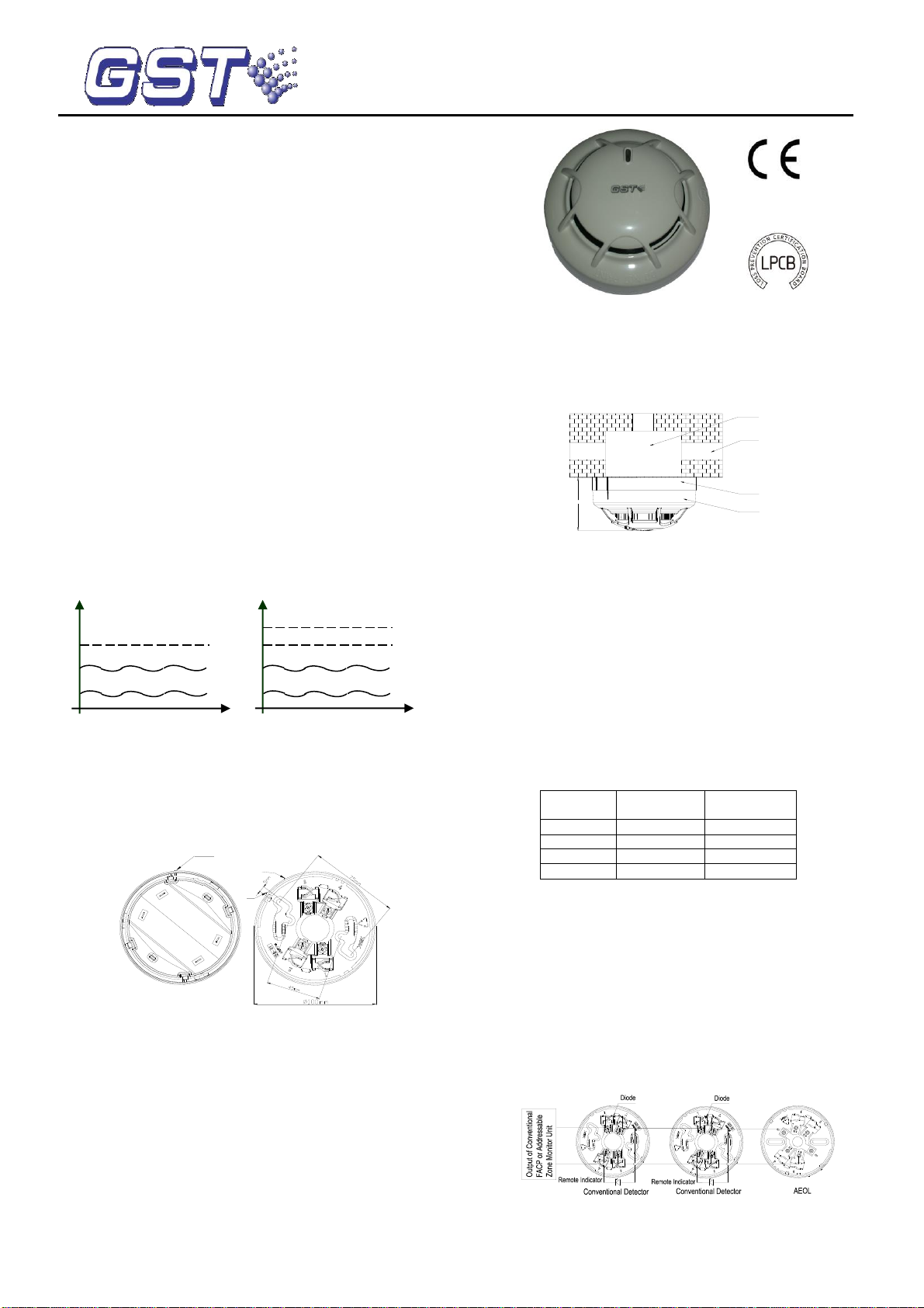
When a remote indicator connects with a few of detectors, a diode
1N5819 needs connecting with Terminal 4 of the orientation base in
series and with anode of the remote indicator. Either DB-01 or DB-01D is
used depends on which DP-9907 Active End of Line Unit or 4.7KΩ
terminal resistor is connected. The system composition is shown in Fig. 8.
O+
O-
Fig. 8
Output loop of the addressable zone monitor unit can be connected with
up to 15 conventional field devices. The addressable zone monitor unit
features loop checking. When the loop is broken, the addressable zone
monitor unit will send fault signal to fire alarm control panel. When any
field device in the output loop is removed, the addressable zone monitor
unit reports fault. If a DP-9907 Active End of Line Unit is connected, it will
not affect the normal operation of other field devices.
Testing
Before testing, please ensure that the detector has been installed
correctly and powered up. After 10 seconds, testing can begin.
1. The detector must be tested after installation and periodical
maintenance.
2. Testing method
1) Magnetic test
Magnetic test zone is shown in Fig. 9. Put the magnet of commission tool
close to that of the detector and hold on for a few seconds until the
detector generates alarm.
Test zone
Fig. 9 Fig. 10
2) Smoke test
Taking a cotton rope burning without flame close to the detector, blow the
smoke into the detector until the detector generates alarm.
3. After testing, cut power for 10 seconds at least and reset the detector.
Notify the proper authorities that the system returns to normal state.
Clean the failure detector in the test according to Maintenance, and test it
again. If it is still fail to pass, please return it to repair.
Maintenance
1. The detector should be installed just before commission and kept well
before installation, taken corresponding measures for dust-proof,
damp-proof and corrosion-proof.
2. The dust cover cannot be removed until the project has been plunged
into usage. Otherwise it can’t alarm normally.
3. Clean the detector at least once a year to ensure normal operation of
the system.
4. If nuisance alarms are often found of the detector on site, the sensing
chamber should be cleaned and replaced when necessary.
a) Open the top cover of detector, and draw out the sensing
chamber by slightly lifting its two sides using a straight
screwdriver, as shown in Fig. 10.
b) Clean the sensing chamber by alcohol cotton swab clipped by
tweezers, and also by clear water and brush. Please note not
to leave any cotton in the chamber.
c) Install the sensing chamber and top cover back.
5. Before cleaning, notify the proper authorities that the system is
undergoing maintenance and will temporarily be out of service. Disable
the zone or system undergoing maintenance to avoid unwanted alarms.
6. The detector should be tested again after cleaning and re-installing.
7. Protect the metal component on the PCB against damp and improper
distortion.
8. Fire simulation test should be made to the detector at least once half a
year.
Specification
Operating Voltage
24VDC(16VDC~28VDC )
Standby Current
≤60μA
Alarm Current
≤55mA
Fire LED
Red, periodically flash once in polling when
the status is set to “ON”; don’t illuminate when
the status is set to “OFF”. Periodically flash
twice in fault or sensing chamber dirty;
illuminate in alarming.
Remote indication
output
Polarity-sensitive output, directly connecting
with remote indicator (built in 10k resistor in
series, max. output current is 2mA); don’t
illuminate when in normal; flash in alarming.
Max. ripple
voltage
2V(peak to peak value)
Alarm reset
Instant power down (10s Min, 1.0VDC Max
Sensitivity setting
The sensitivity can be set by hand held
programmer. There are two sensitivity levels:
level 1 (default), level 2.
Wiring
Two-wire, polarity sensitive.
Environment
Temperature
-10℃~+50℃
Relative Humidity
≤95%, non condensing
Material
ABS
Ingress Protection
Rating
IP2X
Dimension
Diameter:100mm Height: 44.5mm (without
base)
Mounting Hole
Spacing
45mm~75mm
Weight
About 110g
Accessories and Tools
Model
Name
Remark
P-9910B
Hand held programmer
Supplied separately
DB-01
Base
Supplied separately
DB-01D
Base
Supplied separately
DP-9907
Active End of Line Unit
Supplied separately
T-MT
Commission tool
Supplied separately
WEEE Information
2012/19/EU (WEEE directive): Products marked with this
symbol cannot be disposed of as unsorted municipal waste in
the European Union. For proper recycling, return this product
to your local supplier upon the purchase of equivalent new
equipment, or dispose of it at designated collection points.
Limited Warranty
GST warrants that the product will be free from defects in design,
materials and workmanship during the warranty period. This warranty
shall not apply to any product that is found to have been improperly
installed or used in any way not in accordance with the instructions
supplied with the product. Anybody, including the agents, distributors or
employees, is not in the position to amend the contents of this warranty.
Please contact your local distributor for products not covered by this
warranty.
This Data Sheet is subject to change without notice. Please contact GST for more information or questions.
Gulf Security Technology Co., Ltd.
No. 80, Changjiang East Road, QETDZ, Qinhuangdao, Hebei, P. R. China 066004
Tel: +86 (0) 335 8502434 Fax: +86 (0) 335 8502532
service.gst@fs.utc.com www.gst.com.cn

Conventional Manual
Call Point C-9202
Features and Benefits
1. Compatible with latest EN standards
2. Re-settable (non-breaking glass)
3. Additional volt free contact
4. Friendly installation and test
Description
Designed for the purpose of raising an alarm
manually once verification of a fire or
emergency condition exists, by pressing the
non breakable glass. Meets the standard
requirement of EN 54 part 11, European
Standard and approved by Loss Prevention
Certificate Board (LCPB).
The C-9202 constructed of high impact red
ABS with a modern pleasing appearance. The
terminating back box enables first fix
installation and termination leaving the fascia
with integral electronics to be simply plugged
into base at the time of commissioning. Non
breakable glass that can be reset with the
GST standard reset key.
The C-9202 operated via a micro-switch that
when pressed a signal will be transmitted
and the volt free contact will be latched.
Contain integral LED indicator to denote
operational mode.
Selection of compatible Control Panels
Compatible with all GST Conventional panel
and GST Intelligent Fire Alarm Panels using
Zone monitor module.
Technical Specifications
•Standard: EN54-part 11
•Approval: LPCB, CE
•Protection rating: IP 40
•Operating voltage: 24Vdc Loop
•Operating current:
Standby current 0.8mA
Alarm Current 2mA
•Operating temperature: -10°C to
+50°C
•N/O Output contact: 60Vdc, 0.1A
•Contact resistance: 100mΩ
•Relative humidity: 95%
•Application: Indoor use
•Visual Indicator: LED, Red ( lit
steady when alarm, 3 sec interval
blinking at normal state)
•Material and colour: ABS, red
•Wiring: 1 pair polarized
•Dimensions: 97x100x45.5mm
Mounting Base
The location of manual call point should be
installed in compliance with all local codes
and / or NFPA 72 National Fire Alarm Code,
NFPA 70 National Electrical Code. Surface
mount and it is installed onto a standard
one gang electrical box with a mounting
hole that have 52mm~68mm spacing.
Wiring and Connection:
Connect as per the marking on the base.
Ordering Information:
Part No Description Weight
/Kg Pack
Qty per
Box
C-9202 Conventional
Manual Call Point 0.156 120
Note: Specifications are subject to change without notice.
ELECTRICAL
C−9202
MOUNTING
WALL
BACK BOX
BASE
ALARM ACTION
PRESS HERE
FIRE
12
3
4
C−9202 MANUAL CALL POINT
TO NEXT DETECTOR
OR
AEOL
+
−
CONVENTIONAL
PANEL
OR
ZONE
MONITOR
MODULE
K1 K2
O− 0+
I+ I−
DETECTOR


Conventional Optical
Smoke Detector C-9102
Features and Benefits
1. Sensing chamber for exceptional dust
proof ability
2. Built-in Remote Indicator Output
3. Twin LED for 360ºvision
4. Low profile design
Description
With the technique of scattering, the
detector's reliability, stability and consistency
are improved. The special chamber design
ensures the insert-defend, dirt-defend and
anti-light disturbance.
The conventional type can be used directly
with our conventional fire alarm panels.
Using an interface (I-9319), it can be
connected to our intelligent panels.
Technical Specifications
•Standard: EN54-part7
•Approval: LPCB,UL,CE
•Protection rating: IP 32
•Detecting Range:80m² at 6-12meter
ceiling height; and 60m² below
6meter
•
•Operating voltage: 24Vdc (9Vdc to
24Vdc) polarized
•Operating Current:
Stanby: 0.1mA; Alarm:8mA
•Operating temperature: -10°C to
+50°C
•Relative humidity: 95%
•Application: Indoor use
•Material and colour: ABS, off-white
•Wiring: 1 pair polarized
•Dimensions: diameter 10cm; height
5cm
Selection of compatible Control Panels
Compatible with all GST Conventional panel
and GST Intelligent Fire Alarm Panels using
Zone monitor module:
Detector Installation
It is installed onto a standard one gang
electrical box with a mounting hole that
have 6.5cm spacing. Point the detector in
the base by the mark-line and secure the
detector in that position by rotates it
clockwise until it reaches the next mark line.
EMBEDDED BOX
CONCRETE PAD OR
HOLDING PAD
LED INDICATOR
MARK−LINE
ROTATE CLOCKWISE
2ND MARK−LINE
Wiring and Connection
Connect the wires to the required terminal
according to the wiring diagram. Using
active end of line can connect up to 15
detectors and base with diode. Using 4.7KΩ
end of line resistor can connect up to 25
detectors.The cable must be fire rated type
and the size depends on the distance and
application. Minimum size gauge
1.0mm²(18 AWG).
12
3
4
FROM CONTROL PANEL TO NEXT DEVICE
1 PAIR FIRE CABLE 1 PAIR FIRE CABL
E
HOLE
HOLE
C−9314P Remote Indicator
−+
Ordering Information:
Part
No Description Weight
/Kg Pack Qty
per Box
C-9102 Conventional Optical
Smoke Detector
0.12 120
DZ-03 Detector Base -EOLR 0.05 360
DZ-03D Base with Diode AOL 0.05 360
MANUFACTURED IN ACCORDANCE WITH
Note: Specifications are subject to change without notice.
12
3
4
12
3
4
C−9101 SMOKE/HEAT DETECTOR
12
3
4
P−9907 ACTIVE
C−9102 SMOKE DETECTOR
END OF LINE
+
−
CONVENTIONAL
PANEL
OR
ZONE
MONITOR
MODULE

Conventional Sounder
Base C-9402
Features and Benefits
1. High sound level
2. Low power consumption
3. Can be used as a detector base
4. Wall or ceiling mounting. Easy
installation and connection.
Description
In Fire and Security system the sounder is
the most effective device for alerting
personnel to evacuate the area. In the
buildings such as hotels where thick doors
and walls prevent external sound penetration,
the use of a combined detector base with
buit-in sounder present a cost effective
solution.
The GST C-9402 is a non-addressable
sounder base on which can mounted a
conventional detector to provide the dual
function of detection and alarm device or it
can be used as a single sounder.
Technical Specifications
•Operating voltage: 24Vdc (16Vdc to
28Vdc) polarized
•Operating Current: 15mA
•Operating temperature: -10°C to
+50°C
•Relative humidity: 95%
•Sound Output: 85dB @ 1metre
•Application: Indoor use
•Material and colour: ABS, off-white
•Wiring: 1 pair polarized
•Dimensions: diameter 10cm; height :
3.5cm (w/o cover), 4.5cm (w/ cover)
Sounder Installation
The sounder base should be installed in
compliance with all local codes or NFPA 72
National Fire Alarm Code, NFPA 70 National
Electrical Code, BS5389 and EN54. It is
install onto a standard one gang electrical
box with a mounting hole that has 6.5cm
spacing.
ELECTRICAL
WALL
BACK BOX
ELECTRICAL
BACK BOX
CEILING
DETECTOR
C−9402
DETECTOR COMMON
BASE
SOUNDER WITH
COVER
Wiring and Connection
Connect the wires to the required terminal
according to the wiring diagram. The 5,6 is
for 24VDC power supply, note the polarity 5
is positive and 6 is negative. The cable
must be fire rated type and the size
depends on the wiring distance. Minimum
size gauge 1.0mm²(18 AWG).
12
3
4
56
POSITIVE WIRE NEGATIVE WIRE
(5) (6)
POWER SUPPLY/SOUNDER OUTPUT
Selection of compatible Control Panels
Compatible with all GST Conventional panel
and GST Intelligent Fire Alarm Panels using
sounder output and Intelligent Sounder
Driver Module
Ordering Information:
Part No Description Weight
/Kg Pack
Qty
per
Box
C-9402 Conventional
Sounder Base .120 100
Note: Specifications are subject to change without notice.

I General
A conventional fire alarm system usually depends on a resistor at the end of the loop to keep
its normal operation, inappropriate matching will lead to abnormal operation of the whole
system, even result in problems like nuisance alarm. Matching with multi-wire fire alarm
controller or intelligent zone monitor unit, P-9907 Active End of Line Unit (hereinafter called
the unit) takes the place of terminal resistor and solves the above problem, thus increases
reliability of conventional fire alarm system.
II Features
1. Zone two-bus, simple and convenient for mounting and wiring.
2. Fault alarm for removal of detectors.
3. Can be used as the base, sparing space.
4. Stable and reliable performance.
5. Anti-interruption ability.
III Technical Specifications
1. Operating Voltage:
Power Bus Voltage: DC24V Range Allowed: DC15V DC28V
2. Operating Current 5mA
3. Equivalent Resistance: 4.7K
4. Wiring: Zone two-bus, polarized
5. Operating Environment:
Temperature: -10 ~+50 Relative Humidity 95%, no condensation
6. Dimension: 103mm 37.4mm
7. Material and Color of Enclosure: ABS, ivory white
8. Weight: 88g
9. Mounting Hole Distance: 60mm
IV Structure and Operation Principle
1. The bottom is shown in Fig.1.
2. Operation Principle
The unit is installed at the end of zone loop composed of multi-wire fire alarm controller or
intelligent zone monitor unit. When multi-wire fire alarm controller or intelligent zone monitor
unit is powered up and in normal operation, the unit is acting as a load to produce periodic
plus-minus alternating differential pulse signals. Due to the voltage dividing of current
limiting resistor, the filtered power voltage is reduced, the system is in normal operation state.
When the detector is removed, a diode is put in the loop and changes plus-minus pulse to
one-way pulse, reducing the load of the unit and increasing the power voltage after dividing
and filtering. The multi-wire fire alarm controller or intelligent zone monitor unit can judge
fault signal according to this. The judging method of short or broken circuit of zone loop is
similar with the above method.
The unit, matching with multi-wire fire alarm controller or intelligent zone monitor unit, can not
only keep normal operation of conventional fire alarm system, but also alarm fault (without
affecting fire alarm by other field devices) when removing detectors, alarm fault on open
circuit and alarm fire on short circuit, etc.
V Mounting and Wiring
Warning: Before installing the device, disconnect the power from the loop and verify
that all bases are securely installed and that the wiring polarity is correct at each base.
The mounting method of the unit is the same as that of detector base, there are two wiring
mode:
1. When the unit is used as a detector base, a conventional detector can be mounted on it.
Connect the anode of zone loop to terminal "1" and cathode to terminal "3" as shown in
Fig. 2.
P-9907 Active End of Line Unit
Installation and Operation Manual
(Issue 2.0, March 2003)
Fig. 1 Bottom

2. If the unit is not installed with a detector, the anode of zone loop should be connected to
terminal "2" and cathode to terminal "3" as shown in Fig. 3.
VI Testing
Warning: Power up only after all devices are well connected.
1. Test should be made to the unit after installation and at least once half a year after put
into operation.
2. Before testing, notify the proper authorities that the system is undergoing maintenance
and will temporarily be out of service. Disable the zone or system undergoing
maintenance to avoid unwanted alarms.
3. Remove a detector at any position of the tested zone loop, the system should alarm
fault.
4. When the fault is not cleared, make any one of other detectors or manual call points
alarm fire, the system should also alarm fire.
5. Carry out "clear" operation on the controller, the fault and fire should be cleared.
6. After testing, resume the unit. Notify the proper authorities the system is back in
operation.
7. If a unit fails in testing, check its connection and test again. If it still fails, return for
repair.
VII Troubleshooting
1. The system alarms fault after power up:
Check power supply to the zone loop.
2. The system alarms unwanted fire alarm after power up:
Check polarity of power supply to the zone loop reverse or not.
VIII Cautions
1. Polarity of zone loop should not be reversed.
2. When the detector is removed, make sure the diode be in sequence in the circuit.
Global System Technology PLC London EC1R 3AU England
http://www.gstplc.com
Global System Technology PLC
The Intelligent Solution
O-
O+
Output end of
multi-wire
fire alarm
controller or
intelligent
zone monitor
unit
Conventional Detector Conventional Detector Active End of Line Unit
Diode Diode
O-
O+
Diode Diode
Conventional DetectorConventional Detector Active End of Line Terminal
Output end of
multi-wire
fire alarm
controller or
intelligent
zone monitor
unit
Fig. 2 System composition when the unit used as detector base
Fig.3 System composition when the unit not used as a detector base

Anti Tamper Security
Cover C-92FC
Features and Benefits
1. Anti Tamper Security Cover
2. Compatible with I-9202 and DI-9204
3. Easy to install
Description
Designed to protect manual call point from an accidental operation and suitable for 92 MCP
series. The C-92FC constructed of high plastic quality with a modern pleasing appearance.
Technical Specifications
•Material and colour: transparent flexi glass
•Dimensions: 97x100x20mm
Ordering Information
Part No Description Weight/Kg Pack Qty per
Box
C-92FC Anti-Tamper Security Cover 0.02 120
MANUFACTURED IN ACCORDANCE WITH
Note: Specifications are subject to change without notice.

30312280 Issue 1.07
Features
3 classes programmable.
Reed switch testing.
The fire LED allows 360° viewing.
Output terminal for remote indicator available.
Complying with EN 54-5.
Description
DC-9103E Conventional Rate of Rise and Fixed Temperature
Heat Detector is a new generation product of GST. With built-in
microprocessor, it works stably by being fixed with highly reliable
fire judging program.
On detecting a fire signal, it can change its own current to
transmit the signal to fire alarm control panel (FACP) or
addressable zone monitor unit. The detector keeps illuminating
fire LED until it is reset by power-down.
Connection and Wiring
The detector bottom is shown in Fig. 1 and the base in Fig. 2.
C
B
A
Fig. 1 Fig. 2
There are four terminals with numbers on the base.
1: Detection zone positive IN
2: Detection zone positive OUT
3: Detection zone negative IN and OUT
2: Positive terminal of remote indicator
4: Negative terminal of remote indicator
Recommended Wiring
1.0mm2 or above fire cable for all terminals laid through metal
conduit or flame retardant conduit, subject to local codes.
Note: It’s recommended to use cables of different colors to
avoid incorrect wiring.
Installation
First fix the orientation base with two tapping screws. Then align
A (Fig. 1) on the bottom of the detector to B (Fig. 2) of the base,
and rotate the detector clockwise to mark C.
Mounting of the detector is shown in Fig. 3.
Detector
Base
Conduit
Electric Box
53.3mm
Fig. 3
Application
Warning: The alarm current depends on the current limit of
the FACP. 24VDC power cannot be applied to the detector
directly. Otherwise the detector may be damaged for lack of
current- limit resistor.
The default class of the detector is A1R and polling LED status is
“ON” which can be modified using a handheld programmer.
When the programmer is in standby state, entering unlock
password and pressing “Clear”, it will be unlocked. Pressing
Function followed by 4, there will be a “-”at the last digit. Entering
different number corresponding to the parameters followed by
“Program”, there will be a “P” shown on the screen, indicating its
class is programmed. Pressing “Clear” can clear the “P”, and
entering locking password followed by “Clear” will exit.
Table 1 Detector setting parameters
Parameters
Class Polling LED Status
2 A1R ON
3 A2S ON
5 BS ON
130 A1R OFF
131 A2S OFF
133 BS OFF
Read Heat Detector Class: When the programmer is in standby
state, pressing “Test”, it will display address of the detector.
Pressing “Up”, it will display sensitivity level, device type and heat
detector class in turn.
The detector is especially applicable to places where fire occurs
with a sharp rise of temperature. Used together with smoke
detectors, it can help to increase the reliability of fire detection
thus reducing losses.
When the detector is connected with compatible FACP or
addressable zone monitor unit in series, if DP-9907 Active
End of Line Unit (AEOL) is connected to the end of output loop,
a DB-01D base should be used.
If the AEOL is used as the detector base, a conventional
detector can be installed on it. The system composition is
shown in Fig. 4.
Fig. 4
When the AEOL is not used as the detector base, a cover
should be put on it. The system composition is shown in
Fig. 5.
Fig. 5
DC-9103E
Conventional Rate of Rise and
Fixed Temperature Heat Detector
548c/03
2831-CPR-F0005
GST-0005-01
14

30312280 Issue 1.07
30° Testing
Area
Fig. 8
When the detector is connected with conventional FACP or
addressable zone monitor unit, if a 4.7kΩend of line resistor is
connected to the end of output loop, DB-01 base is used. The
system composition is shown in Fig. 6.
Fig. 6
When multiple detectors are connected with a remote
indicator, a diode 1N5819 should be connected to Terminal 4
of the orientation base in series before going to the positive of
the remote indicator. System composition is shown in Fig. 7.
Fig. 7
Maximum 15 detectors can be connected to the output of zone
monitor unit. In case of broken circuit or removal of any detector,
the unit will transmit a fault message to the FACP. If and AEOL is
connected, normal operation of other device in the system will not
be affected.
Testing
Note: Before testing, make sure the detector is properly
installed and powered up. Testing can only begin after the
detector is powered up for 10 seconds.
The detector must be tested
after installation and regular
maintenance. The methods are
as follows:
(1) Reed switch testing
The testing area of the detector
is shown in Fig. 8.
Approach the commission tool to
the testing area of the detector
and hold for several seconds
until the detector alarms.
(2) Temperature test
Approach a heater (such as a hair drier) to the thermistor of the
detector until it alarms.
After testing, disconnect power to the detector for over 10
seconds to reset it. Notify the proper authorities that the system is
back to normal operation.
If a detector fails in testing, clean it by the steps in “Maintenance”,
and retest it. If it still fails, return it for repair.
Maintenance
The detector should be installed just before commission and
kept well before installation, taken corresponding measures
for dust-proof, damp-proof and corrosion-proof.
The dust cover cannot be removed until the project has been
plunged into usage.
Clean the detector at least once a year to ensure normal
operation of the system.
Before cleaning, notify the proper authorities that the system
is undergoing maintenance and will temporarily be out of
service. Disable the zone or system undergoing maintenance
to avoid unwanted alarms.
The detector should be tested again after cleaning and
re-installing.
Protect the metal component on the PCB against damp and
improper distortion.
Do fire simulation test at least once every 6 months.
Specification
Operating Voltage 24VDC(16VDC~28VDC)
Standby Current ≤60μA
Alarm Current ≤55mA
Fire LED Red, periodically flash once in
polling when the status is set to
“ON”; don’t illuminate when the
status is set to “OFF”. Periodically
flash twice in fault; illuminate in
alarming.
Remote Indication
Output
Polarity-sensitive, directly
connecting with remote indicator
(built in 10k resistor in series,
maximum output current is 2.0mA);
The remote indicator does not
illuminate in normal and flashes in
alarm.
Class and Setup Classes A1R, A2S, BS
programmable.
Maximum Ripple
Voltage
2V ( peak-to-peak)
Alarm Reset Instantaneous cut-out (10s Min,
1.0VDCMax.)
Wiring Polarized two wire
Ingress Protection
Rating
IP2X
Ambient Temperature Class A1: -10℃~+50℃
Class A2: -10℃~+50℃
Class B: -10℃~+65℃
Typical Fixed
Temperature
Class A1: 58℃
Class A2: 62℃
Class B: 77℃
Relative Humidity ≤95%, non-condensing
Material ABS
Dimensions Diameter: 100mm
Height: 53.3mm (with base)
Mounting Hole Spacing
45mm~75mm
Weight About 110g (with base)
Accessories and Tools
Module Name Remarks
P-9910B Handheld Programmer Order separately
DB-01 Base Order separately
DB-01D Base Order separately
DP-9907 Active End of Line Unit Order separately
T-MT Commission Tool Order separately
WEEE Information
2012/19/EU (WEEE directive): Products marked with this
symbol cannot be disposed of as unsorted municipal waste
in the European Union. For proper recycling, return this
product to your local supplier upon the purchase of
equivalent new equipment, or dispose of it at designated
collection points.
Limited Warranty
GST warrants that the product will be free from defects in design,
materials and workmanship during the warranty period. This
warranty shall not apply to any product that is found to have been
improperly installed or used in any way not in accordance with
the instructions supplied with the product. Anybody, including the
agents, distributors or employees, is not in the position to amend
the contents of this warranty. Please contact your local distributor
for products not covered by this warranty.
This Data Sheet is subject to change without notice. Please contact GST for more information or questions.
Gulf Security Technology Co., Ltd.
No. 80, Changjiang East Road, QETDZ, Qinhuangdao, Hebei, P. R. China 066004
Tel: +86 (0) 335 8502434 Fax: +86 (0) 335 8502532 service.gst@fs.utc.com www.gst.com.cn

Smoke Alarm S-9102
Features and Benefits
1. Self contain Optical Smoke detector
and alarm sounder
2. With test and reset button
3. 9v operated
4. Low battery indication
5. Battery removable will inhabit cover
from closing ( as per UL standard)
6. Easy installation
7. LED indicator for 360ºvision
8. Connection port to link up to 30
detectors in a single network
9. Output to interface with other
security equipment
Description
S-9102 Smoke Alarm is designed for
domestic usage such as a house, villa and
apartment, etc. Built with high-quality
components and advanced technology, the
alarm has an excellently stable performance
and low power consumption. A 9V battery
will operate up to one year. It can be easily
installed, no commission required.
Utilize internal buzzer to provide a loud local
alarm. By using the output terminal, the
alarm can be linked to other alarms in a
common alarm network (up to 30 alarms) or
can be interfaced to other systems.
Technical Specifications
•Power Supply: PP3 (H6F22) DC9V
battery
•Indicator: Red flashes in every 50
seconds in normal condition.
•Output Interface: Available for
optional use
•Network Output: Maximum 30
alarm in one system, available for
optional use.
•Photoelectric Output: 5mA /30VDC,
Optional
•Sound level : 80dB
•Detection Area: 40m2
•Operating Environment:
•Temperature: -10~ +50
•Relative Humidity: 95%
•Dimension: 140 x 54mm(D x H,
with base)
•Material and Color: ABS white
•Weight: 235g
•Mounting Hole Distance:
50mm~108mm
Detector Installation and Wiring
The Smoke Alarm should be installed in
compliance with all local codes having a
jurisdiction in your area or NFPA 72
National Fire Alarm Code, NFPA 70 National
Electrical Code, BS 5389 and EN54. For
information about installation refers to
manual.
Ordering Information:
Part No Description Weight
/Kg Pack
Qty
per
Box
S-9102 Smoke Alarm 0.300 30
MANUFACTURED IN ACCORDANCE WITH
Note: Specifications are subject to change without notice.


CONTENTS
IDescription ................................ 1
II Specification.............................. 1
III Structure.................................... 2
IV Mounting and Wiring................. 3
VApplication................................. 6
VI Troubleshooting......................... 7
VII Maintenance.............................. 8
VIII Cautions.................................... 8
IX Warranty Limited ....................... 9

1
I Description
C-9602LW Conventional Gas Detector is
wall-mounted, designed to check and monitor
the gas of leakage in such applications as
houses, hotels and apartments.
II Specification
1. Operating Voltage:187VAC~253VAC
2. Power Consumption:
Standby State≤3.0 W
Alarm State≤5.0 W
3. Output capacity and control mode:
Voltage contact: For 12VDC one-way pulse
solenoid, whose driving capability is 1000µF
capacitance discharge.
Volt-free contact: Volt-free normally open
contact, its capacity is 220V/1A used for
controlling connected devices.
4. Alarm Density:
Natural Gas: 3000×10-6 (6%LEL)
Liquefied Petroleum Gas: 2000×10-6(10%LEL)
Coal Gas: 400×10-6(1%LEL)
5. Indicator:
Power LED: Green, flashes in warm-up state
and then constantly lights.
Other manuals for C-9101
1
Table of contents
Other GST Smoke Alarm manuals
Popular Smoke Alarm manuals by other brands

System Sensor
System Sensor A05-1003-002 Application guide

DSC
DSC FSA-210 Installation and operating instructions

ELRO
ELRO FS1105P quick start guide

Honeywell
Honeywell FCI 2451 Series installation guide

System Sensor
System Sensor 1251B Installation and maintenance instructions

PNI
PNI SafeHouse HS260 user manual