In the delivered condition the button clamp is depressed position, freeing the
channels for input wires (Figure 9). Wiring loop carried out in the following
sequence:
- Enter into the channel wire and fix it, having drawn the button clamp to the stop
(Figure 10);
- Check the connection for which you need to press bending contact, simulating the
pressure sensor (Figure 10) and pull the wire itself;
WARNING: AFTER THE INTRODUCTION OF A COMPULSORY LOCK WIRE LOOPS, PUSHING THE
BUTTON.
- To get the wire into the slot located on the button clamp (Figure 10).
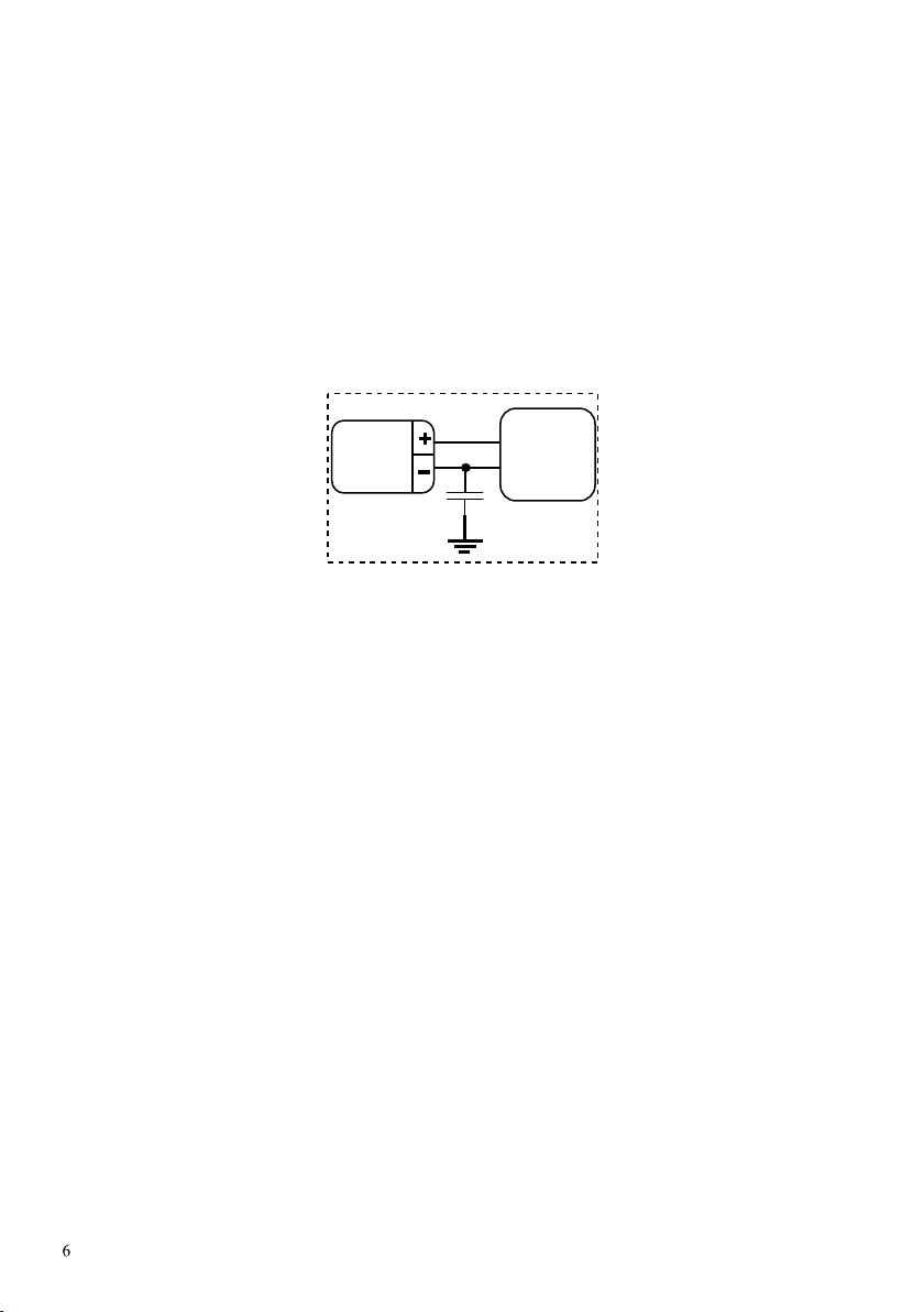
WARNING!!! IT IS RECOMMENDED TO GROUND A NEGATIVE LEAD OF POWER SUPPLY OF THE
CONTROL PANEL THROUGH A NON-POLAR CAPACITOR WITH CAPACITANCE 0,1–0,47 мсF ×
400 V (OR MORE) OF FIRE ALARM SYSTEM. IN ORDER TO INCREASE NOISE IMMUNITY
EXAMPLE: K73-17, 0.1 F 630 V (FIGURE 11).мс
С
0,1мcF
630V
Power
supply
Control
panel
Figure 11
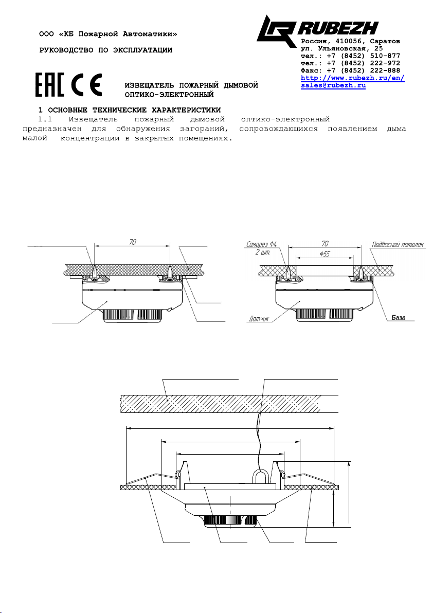
3.5. Set the sensor to the base.
3.6. After the installation of fire alarm system should:
- To establish standby system using alarm control the surf;
- Check the detector performance using a pin diameter less than 1 mm or
"Tester-2" Frontier introduced into the smoke chamber for up to 9 through the hole
on the cover of the detector;
- Make sure to include activated LED and detector signal reception "Fire" by
the control panel;
– Remove the detector from the socket and make sure to reception of a signal
"Fault" by the control panel;
- Insert the probe to the base;
– Set the standby system.
3.7. Protective cap, supplied with each detector, designed to protect the
smoke detector camera from dust during transport and storage. The protective cap
must be put on the detector during the decoration in the room, to avoid contact
with it particles of building materials, dust, moisture, and also for protection
against mechanical damage.
To eliminate false positives due to the dust of the optical system of the detector
must be not less than once every six months to clean the smoke chamber from dust.
for this qualified personnel is allowed to remove the smoke chamber to clean or
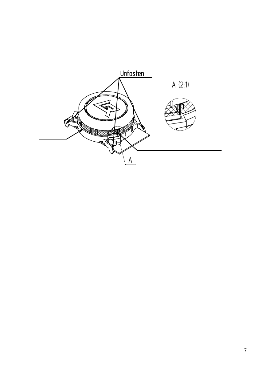
replace it. The procedure for replacing the smoke chamber:
a) position the sensor label side up, gently squeeze the four locks and detach
the cover from the base of the detector;
b) soft jumper straighten and remove it from the grid;
c) overcome the locks on the smoke chamber (Figure 12) and remove it together
with the grid;