GU Electronic MB 2015 PAS User manual

1
Instruction Manual
MB_2015_PAS with PAS for Mercedes Benz

GU Electronic
INDEX
Specifications
1. Main Spec. ---------------------------------------
2. Diagram ------------------------------------------
3. Components -------------------------------------
4. Components (Option) ---------------------------
5. Exterior -------------------------------------------
Settings
1. Dip Switch ---------------------------------------
2. ParkingàDrive ----------------------------------
3. Original button ---------------------------------
4. OSD Menu --------------------------------------
Installation
1. Diagram -----------------------------------------
2. LVDS Connection -------------------------------
3. CAN Connection --------------------------------
Caution
1. FQA -----------------------------------------
2. Caution ----------------------------------------
2
3
4
5
6
7
8
9
10
12
17
18
19
20
20

GU Electronic
Specification
1. Main spec.
1-1 Input Spec. (MULTI VIDEO INTERFACE)
- 1 x Analog RGB Input (Navigation System output)
- 1 x CVBS(REAR CAMERA) Input. (Rear camera source)
- 1 x CVBS(FRONT CAMERA) Input. (Front camera source)
- 1 x LVDS Input. (Car Command System)
- 1 x HDMI Input. (Car Command System)
1-2 Output Spec.
- 1 x LCD Output (LCD Operation)
1-3 Power Spec.
- Input Power : 8VDC ~ 24VDC
- Consumption Power : 12Watt, Max
1-4 Switch Input mode
- Possible to switch input mode through original button (p. 10)
2. Features
- Easy installation with Plug&Play power/LVDS cable
- Display dynamic PAS(Parking assistance system) with PDC
- Capacitive touch screen with frame (option – Refer to P.7)
3
GU Electronic
Specification
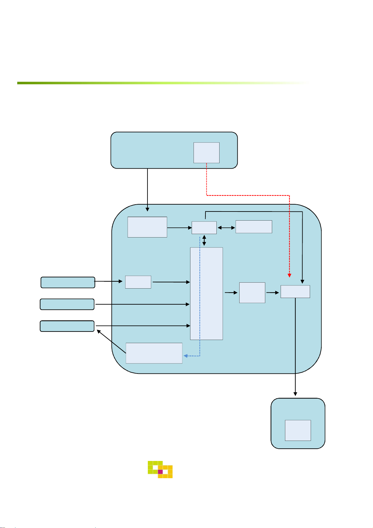
3. Diagram
4
Scaler
(PIP)
MCU EEPROM
CAN
RECEIVER
LVDS
TX RELAY
REAR CAMERA
POWER
LVDS
TX
CAR
COMMAND
SYSTEM
CAN
RGB+Syn
REAR CAMERA
DIGITAL RGB LVDS
INTERFACE
CAR
TFT-LCD
LVDS
RX

GU Electronic
Specification
4. Components
Power Cable 1 EA LVDS Cable 1 EA
RGB Navi Cable 1 EA
5
OSD Board 1 EA

GU Electronic
Specification
4. Components (Option)
6
RGB Cable 1 EASub Board 1 EA
HDMI Cable 1 EA
MHL Cable
Galaxy S4
Galaxy S3
Galaxy S2
Iphone5/6
GU Electronic
Specification
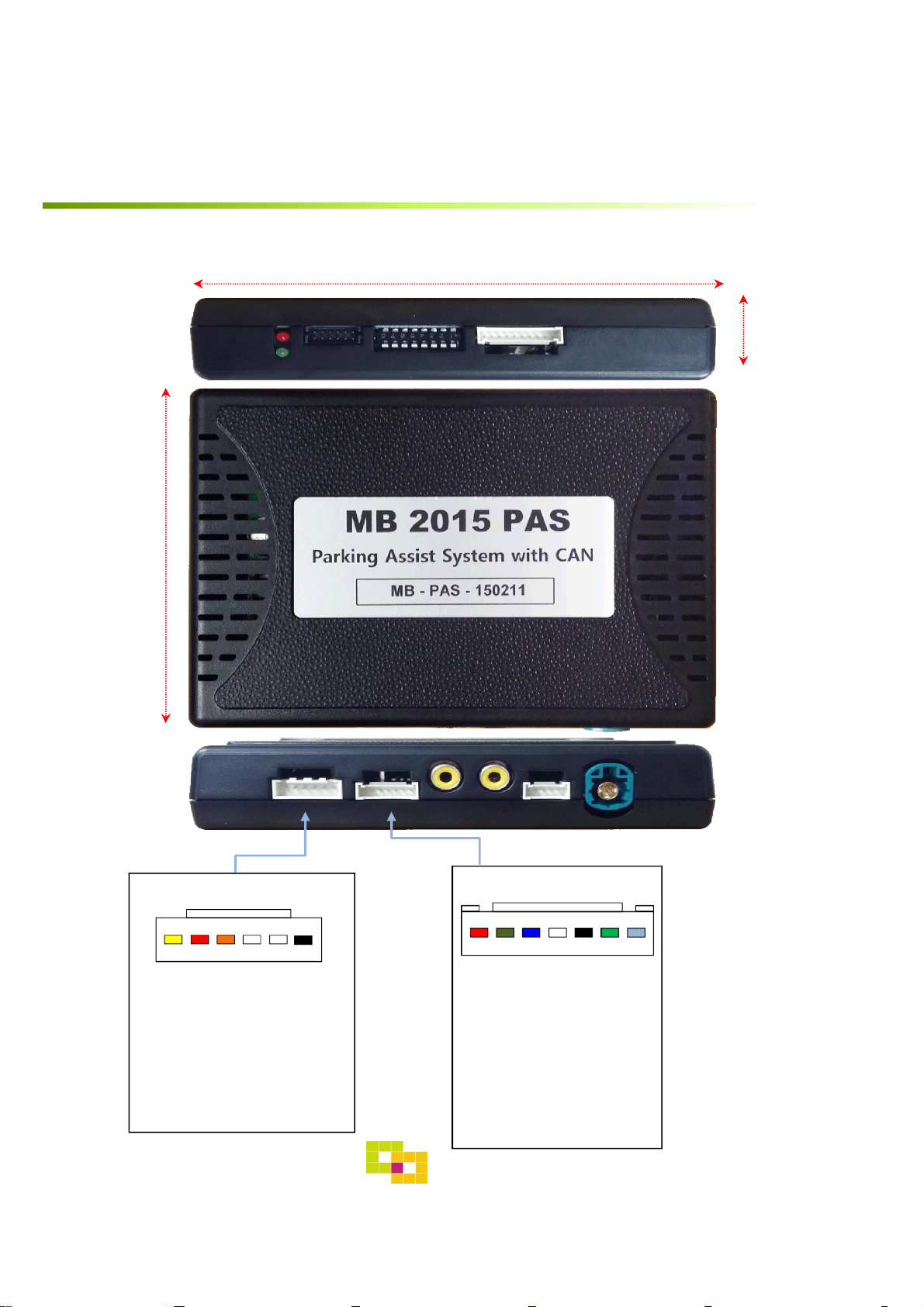
5. Exterior 116mm
21mm
83mm
7
*NAVI Connect
① R DATA (Red)
②G DATA (Green)
③B DATA (Blue)
④SYNC (White)
⑤GND (Black)
⑥NC
⑦+5V
①②③④⑤⑥⑦
LED DIP S/W PROGRAMIMAGE
POWER/CAN LCD-OUTLCD-INFRONT REARNAVI
*POWER Connect
① BATTERY (Yellow)
②REAR_POWER (Red)
③CAN-HIGH (Orange)
④CAN-LOW (White)
⑤NC
⑥GND (Black)
①②③④⑤⑥
Settings
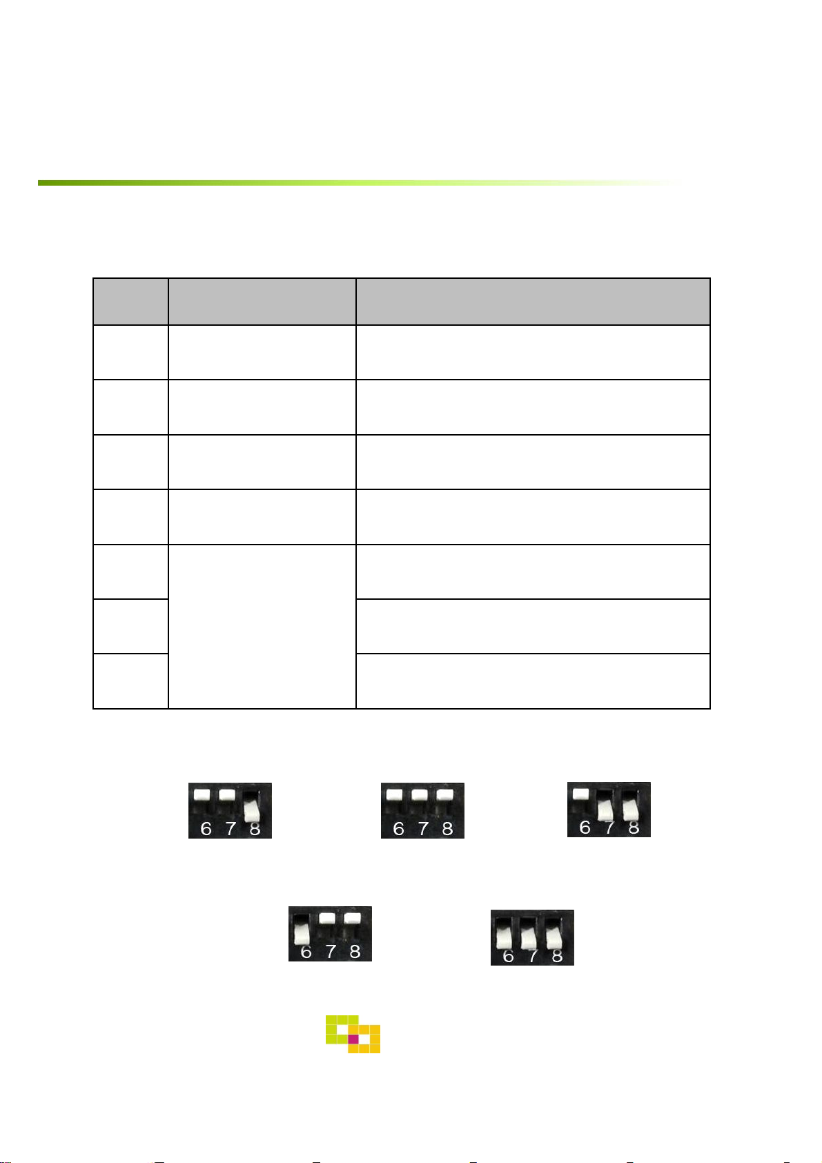
1. Dip Switch
* ON : DOWN , OFF : UP
NO. Function Selection
1 NAVI (MHL) ON : Skipping NAVI (MHL)
OFF : Display
2 Video mode ON : Skipping Video
OFF : Display
3, 4 N.C
5 Rear Camera Page. 8
6
Car model
ON : B,E,CLA,CLS,GLE 7”, 8”
7 ON : S 12”, 12” Split view
8 ON : S : 12”, 12 Split view, C 8.4”
* Example
8
GU Electronic
C class 8.4”Model S class 12”Model
E/B/CLA/CLS/GLE class
7”/8”Model S class 12”split view
C/GLC class 7”Model
Aston martin vantage2018

Settings
2. Parking àDrive setting
•Setting time to display screen when changing gear from P to N or D
: Dip S/W No.5 “OFF”
Rear Mode
After 15sec. in N,D gear
After driving up 10km
OR
: Dip S/W No.5 “ON”
Rear Mode
Display
Display
Right after changing gear
9
- The rear screen is displayed for 15sec in N, D gear or until driving up
10km – OEM type
- The rear screen is switched right after changing gear
GU Electronic

Settings
3. Original button
10
※ The button in Jog shuttle can’t be used in the Car with NTG 5.1
system as this interface has only one pair of CAN wire (the CAN data
of Jog shuttle system in NTG5.1 is different from the steering wheel)
※ MB2015 TAC2 interface is recommended for using the button in Jog
shuttle in NTG 5.1
- Switching mode
/ NAVI : 1. Long Press: Switching mode
2. Short Press: Switching to OEM directly
Steering wheel Jog shuttle
Steering wheel Jog shuttle
GU Electronic
Table of contents


