Guardian Telecom Inc. Installation and Operation
Desktop Ringdown Telephones DTR-51-Z & DTR-61-Z
Page 6
•The DTR ZONE 1 ringdown telephone utilizes the features of the PABX to route
calls to the desired location.
•Follow all appropriate electrical codes and use only approved electrical fittings for
the installation.
•If required install primary surge protection outside of the classified area.
•
Ensure that none of the electrical connection circuits are live by disconnecting the
Tip and Ring conductors at the demarcation block or PABX.
•If the built in Ring Detect Relay is to be utilized to activate an external alarm
ensure that the power conductors are not live.
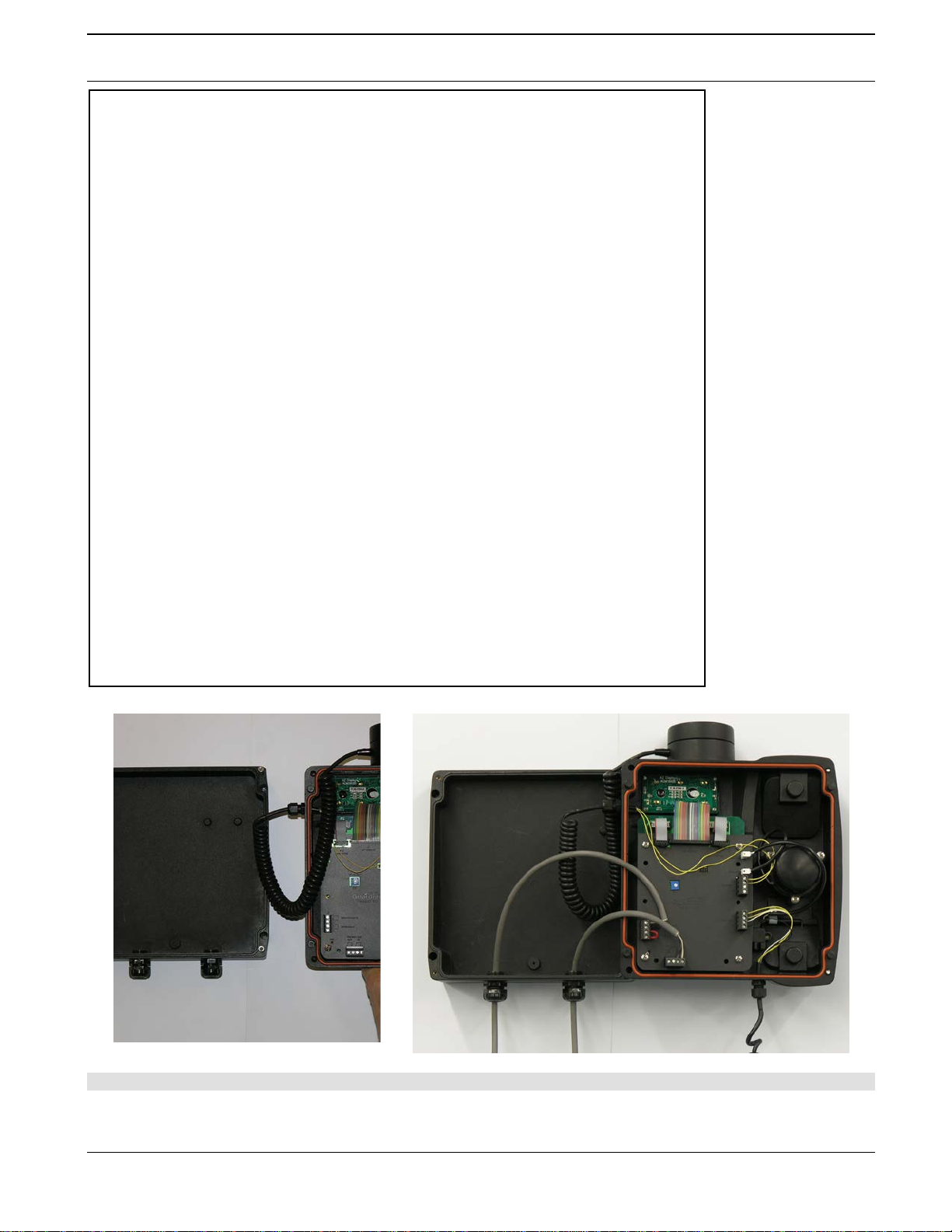
•Using the 3mm Allen Key provided loosen the four faceplate captive screws to
detach the faceplate from the base.
•The telephone may be installed on a flat surface or wall mounted.
•
If the telephone is to be desk top mounted set the base in the desired location.
Wall Mount Configuration
•If the telephone is to be wall mounted choose a location that is free of
obstructions and permits space for wiring. Mount the base with the deepest
dimension on the bottom. Mount as follows:
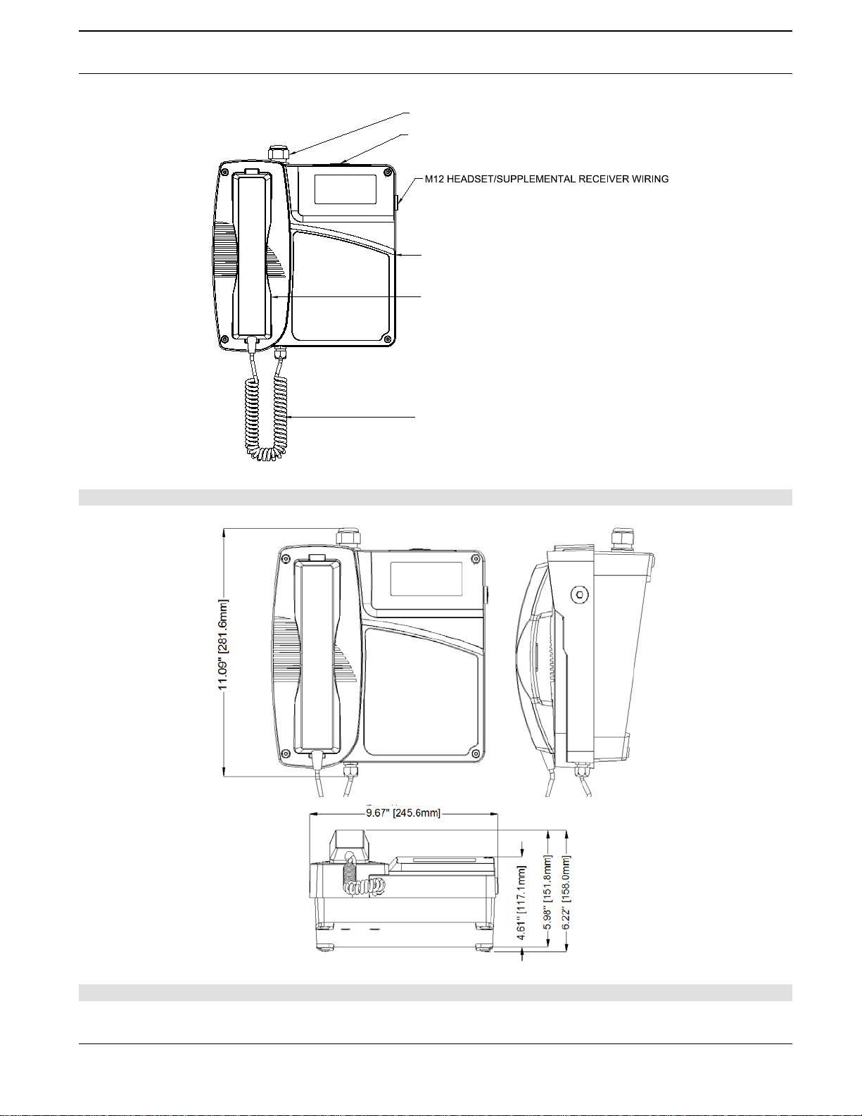
See: Figure 2 - Overall
Dimensions.
The telephone weighs 3.95 kilograms (8.68 pounds), ensure that the
mounting can support four times the weight of the unit; that is 15.8
kilograms (34.8 pounds).Wall anchors are not included; follow the
manufacturer’s instructions when installing anchors.
Mounting to concrete or cinder block. Lead expansion anchors with M4
(#8) screws are recommended.
oMounting to drywall. Hollow wall anchors (Molly Bolts) with M4 (#8)
screws are recommended.
oMounting to other surfaces. It is the responsibility of the installer to
ensure that the base is attached in such a way as to support the weight
specified above.
•Install the handset retainer clips on the faceplate using the hardware supplied.
Special Conditions for Safe Use (Gas & Dust)
(1) The enclosure must be opened in a non-hazardous location in order to make
the necessary connections. The connecting cable must be suitable for use in the
EX environment (see IEC60079-14 & IEC61241-14) and be secured using the
cable gland provided.
(2) The volt free contacts for the ring detect circuit must only be connected to
external equipment suitably rated for its end-use EX environment (see
IEC60079-14 & IEC61241-14) and be secured using the cable gland provided.
(3) During installation, it must be ensured that external wiring to connectors J1
and J2 must be sheathed to within 10mm of the terminals. External wiring shall
be rated for a minimum of 250V and run so that 50mm separation is maintained
between wiring and terminals/connectors other than J1 and J2.


 User manual")